

Page 1
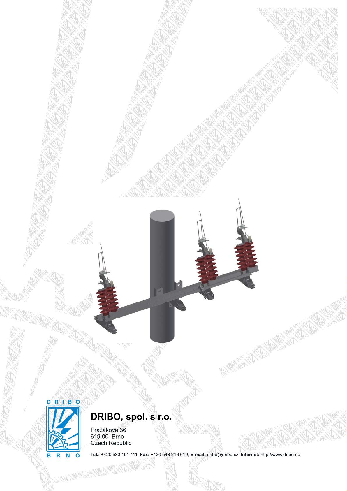
Instructions for assembly,
operation and maintenance
of outdoor load disconnectors
Fla 15/60 GB R N and Flc GB R N
three-pole design
for mounting on concrete pole
rated voltage 25 and 38.5 kV
rated current 400/630 A
1
Page 2
General
Outdoor devices of Fla 15/60 GB R N and Flc GB R
N series are load disconnectors according to the EN
62271-103 standard. They are manually or motor
operated. Motor drives are designed especially for
remote control.
The GB R N series load disconnectors are universal
devices for mounting into the line (on the top of a
In the Fla 15/60 load disconnectors, disconnecting
takes place in a low-oil volume quenching chamber.
The Flc GB load disconnectors are equipped with a
special sprig quenching mechanism.
The manufacturer does not assume liability for
damage and operating faults caused by not
observing the installation instructions.
pole) or for mounting under the lines (continuous
disconnector or branching).
Climatic conditions
Maximum temperature °C + 40
Minimum temperature °C - 30
Maximum relative air humidity % 100
Maximum wind pressure Pa (m/s) 700 (34)
Maximum ice or hoar-frost thickness mm 20
Typical altitude m a.s.l up to 1000
For use in higher altitudes please consult the manufacturer.
Handling and storage
During transport and handling, disconnectors
may only be lifted at the base frame, never at the
quenching chambers or at the current path or
insulators.
Storage is allowed in both indoor and outdoor
spaces. Store devices on a level surface. Protect
devices against damage during transport and
handling.
List of necessary tools and tightening torques
Tool Size
Ring spanner 24
Engineer’s spanner 24
Socket spanner (GOLA) 17 (16)
Socket spanner (GOLA) 30
Torque spanner – see the table of tightening torques Clamping tongs for stainless fixing band (e.g. Bandimex W 001, Band-It) Stainless fixing band (e.g. Bandimex B 206, Band-It) width 19 mm, thickness 0.75 mm
Clamp for stainless fixing band (e.g. Bandimex S 256, Band-It) width 19 mm
Tool part / joint Torque
Clamping terminal yokes 30 Nm
Connecting lug bolts (power leads) 75 Nm
Device installation on pole
A. Installation of disconnector into the line (on the top of a pole)
The disconnector is installed on a concrete pole using two sleeves R 120 (Fig. 2, pos. 9). The prescribed pole
diameter in the point of fixing the device is 220 – 245 mm.
The upper sleeve is provided with a suspension for the middle conductor.
B. Installation of disconnector under the line (continuous, branching)
The disconnector is installed on a concrete pole using two sleeves R 130 (Fig. 1, pos. 9). The prescribed pole
diameter in the point of fixing the device is 240 – 265 mm.
The disconnector is to be positioned on the support in such a way that the height of the connecting conductor
above the ground at the distance of 2 m to the support was not smaller than 5.5 m with regard to the means of
mechanization which may move around the support point.
2
Page 3
Installation of drive, intermediate bearings and pull rods
Depending on the fixing height of disconnector, the drive assembly comprises one of two intermediate bearings.
• Only one intermediate bearing is normally used for disconnectors installed under the line (continuous,
branch – for 10.5 m poles.
• Two intermediate bearings are used for disconnectors mounted into the line (on the top of a pole – for
10.5 m and 12 m poles) and for poles mounted under the line (continuous, branching – for 12 m poles).
The first intermediate bearing under the disconnector must be only a pendulum intermediate bearing (with barrel).
The assembly of intermediate bearings can be seen in Fig. 3a and Fig. 3b, respectively.
When assembling and setting the drive, the disconnector is in the switched-on position on the ON stop.
Fix the manual drive T on the concrete pole using the sleeve (Fig. 1 or Fig. 2, pos. 2) at a height of approx. 1350
mm above the ground. Banding the lower part of the drive is done after the complete banding and testing of the
drive function.
Assembling the drive with one intermediate bearing (Fig. 1)
Connect the upper (flattened on both sides) pull rod tube (pos. 7) to the operating lever on the device (pos. 8)
using the pin.
Fix the intermediate bearing (pos. 3) to the lower end of the upper tube. Position the fixing base of the
intermediate bearing to the pole so that the intermediate bearing lever is tilted up at the angle of 45°.
Fix the intermediate bearing in this position to the pole with two bands.
Slide the lower pull rod tube with the end with hole on the socket of manual drive T (pos. 5) and secure with the
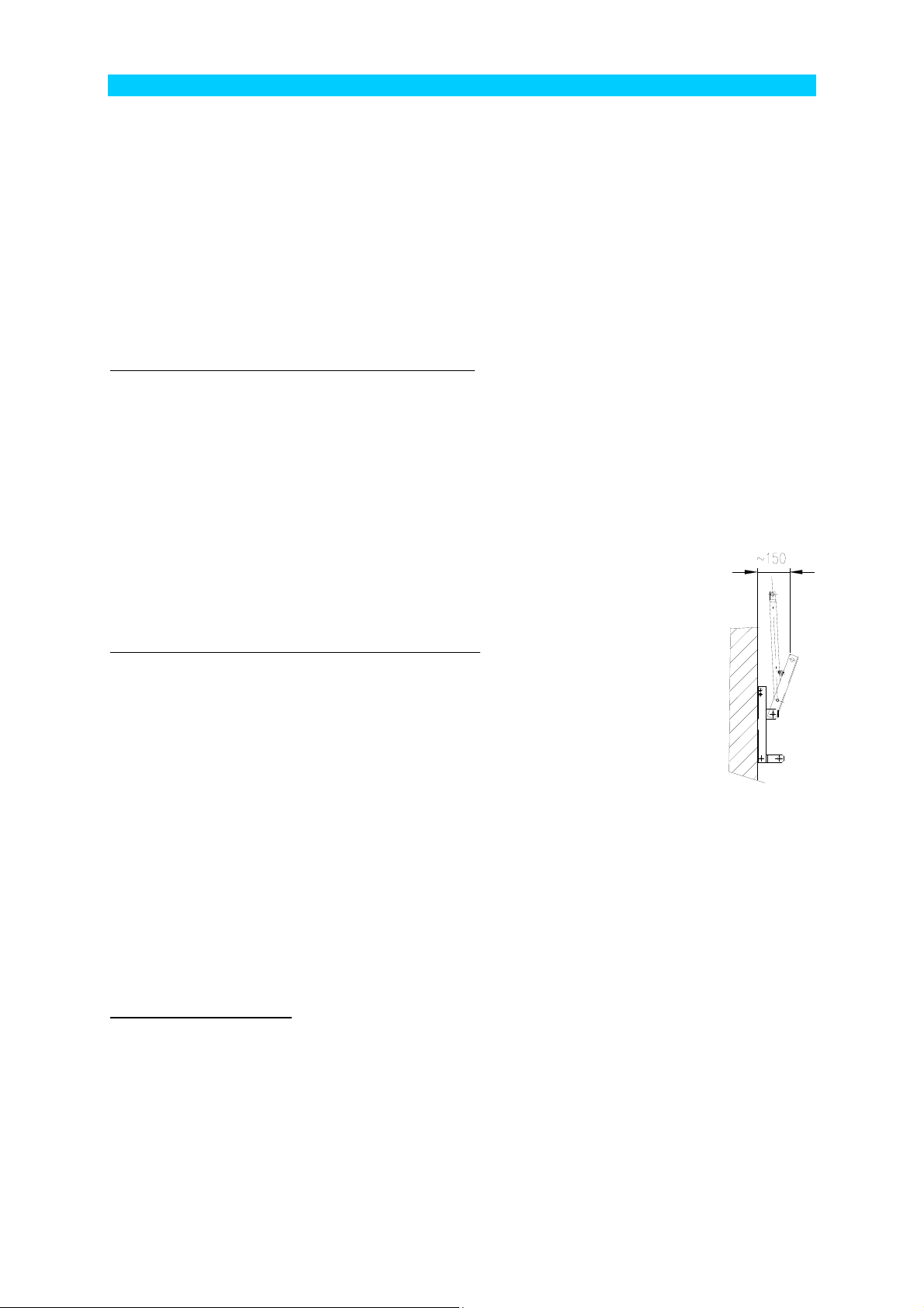
provided screw. Move the drive lever to the switched-on position – the lever directs vertically. After swinging the
lever by approx. 150 mm (see the figure; in this way the necessary pretension of the pull rod in the switched-on
position is reached) measure the necessary length of the lower pull rod tube and shorten it. Shorten the tube
from its upper part – the one without holes!
When shortened, screw the lower pull rod tube (pos. 5) together with the manual drive (pos. 1).
Slide the upper end of tube into the yokes of the intermediate bearing (pos. 3) and tighten the
yokes by the prescribed torque.
Assembling the drive with two intermediate bearings (Fig. 2)
Using the pin, fix the upper (flattened on both sides) pull rod tube (pos. 7) to the operating lever
on the device.
Fix the upper intermediate bearing (pos. 3) to the lower end of the upper pull rod tube. Position
the fixing base of the upper intermediate bearing to the pole so that the intermediate bearing
lever is tilted up at the angle of approx. 45° and fix it in this position to the pole with two bands.
Slide the lower pull rod tube (pos. 4) with the end with hole on the socket of manual drive T (pos.
1) and fix with the provided bolt and nut. By means of the pin, fix the lower intermediate bearing
(pos. 4) to the upper end of the lower pull rod tube (pos. 4).
Turn the drive to switched-on position. In this position fix the lower intermediate bearing (pos. 4) with two bands –
after fixing, the intermediate bearing lever must be in parallel with the upper intermediate bearing lever (directing
up at the angle of approx. 45°).
Fix the middle pull rod tube (pos. 6) with the flattened end to the lower intermediate bearing (pos. 4). When tilting
the operating lever of the manual drive (pos. 1) 150 mm from the pole (for the necessary pretension in switchedon position and for elimination of pull rod clearances), measure the necessary length of the middle pull rod tube to
the upper intermediate bearing (pos. 3) and shorten from the upper end.
After shortened, slide the middle pull rod tube (pos. 6) into the yokes of the upper intermediate bearing (pos. 3)
and tighten the yokes by the prescribed torque.
Function test after installation
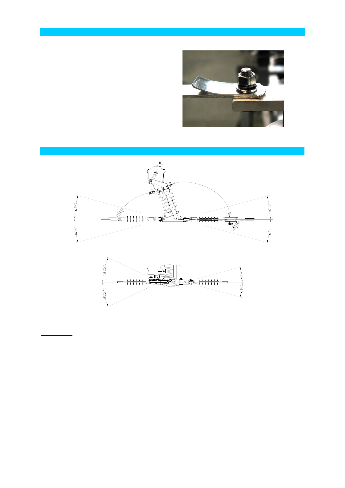
Operate the drive to the OFF position to disconnect the main contacts. Then operate to the limit ON position. In
the limit ON position, the disconnector must reliably reach the switched-on position (Fig. 4, control points A and
B). Contacts must be fully retracted and the stop on the device must reach the limit position. Intermediate
bearings must not thrust and no deflection of the pull rod tubes must occur (a threat of damage to the drive).
If the limit position of the device is not reached (control point B), make correction by changing the length of the
lower (or middle in the case of the drive with two intermediate bearings) of pull rod tube within the limits of
possible shift on the clamping terminal of the upper intermediate bearing (Fig. 1 and 2, respectively, pos. 3). If a
larger correction is required, the pull rod must be replaced or the drive shifted.
On the disconnector, check that the moving contact is retracted in the main contact properly (Fig. 4, control point
A). If the disconnector does not have the correct clearance in contacts despite reaching the ON position stop,
check that the contact system was not damaged during transport.
3
Page 4

The device must reliably reach the stops in both limit positions.
After making contacts several times and checking the correct function of the drive and disconnector, check that all
joints are tightened properly.
After testing, secure the T drive (Fig. 1 and 2, respectively, pos. 1) with the band.
Assembly of the drive of disconnectors type GB R N with one bearing
Disconnectors for installation under the line (continuous, branching – for 10.5 poles)
1. T-type manual drive
2. Sleeve assembly R178
3. Banding-type intermediate bearing (with barrel, flattened tube up, clamping terminal down)
4.
5. Lower pull rod tube (to drive/adjustable)
6.
7. Upper pull rod tube (flattened/flattened)
8. Operating lever of the device (part of the device)
9. Sleeve assembly R130 (2 pcs)
Fig. 1
Assembly of the drive is identical also to disconnectors Fla 15/60 GB R N.
4
Page 5
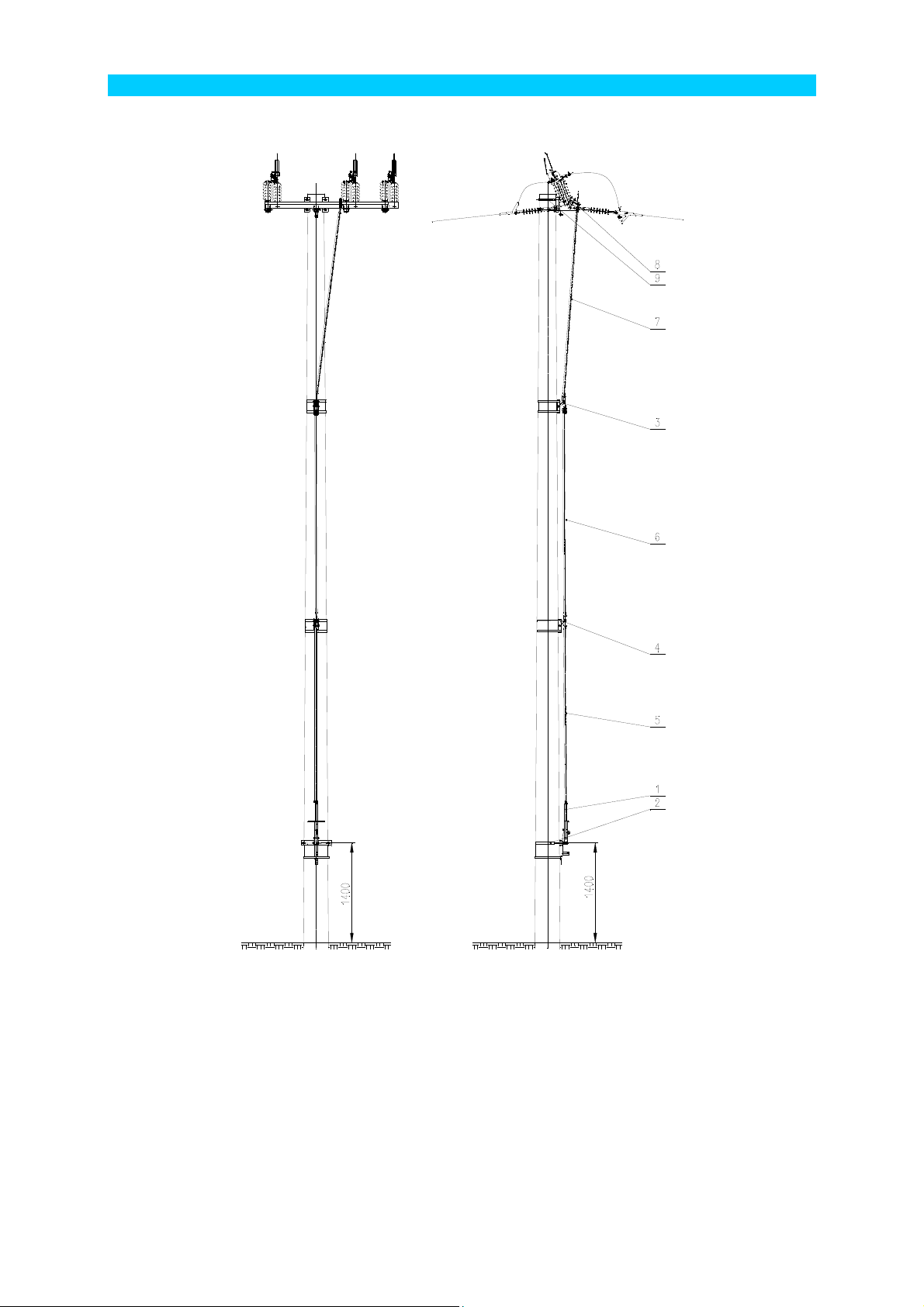
Assembly of the drive of disconnectors type GB R N with two bearings
Disconnectors into the line (on the tope of a pole – for 10.5m and 12m poles) and disconnectors for mounting
under the lines (continuous, branching – for 12m poles)
1. T-type manual drive
2. Sleeve assembly R178
3. Upper banding-type intermediate bearing (with barrel, flattened tube up, clamping terminal down)
4. Lower banding-type intermediate bearing (flattened tube up, flattened tube down)
5. Lower pull rod tube (to drive/flattened, length 2000)
6. Middle pull rod tube (flattened/adjustable, length 3000)
7. Upper pull rod tube (flattened/flattened, length 2500)
8. Operating lever of the device (part of the device)
9. Sleeve assembly R120 (2 pcs, the upper one with the middle cable suspension), for disconnectors for
mounting under the line – sleeve assembly R130 (2 pcs)
Fig. 2
Assembly of the drive is identical also for disconnectors Fla 15/60 GB R N and for disconnectors Fla
15/60 GB R and Flc GB R N in the case of suspension mounting on a 12m pole.
5
Page 6
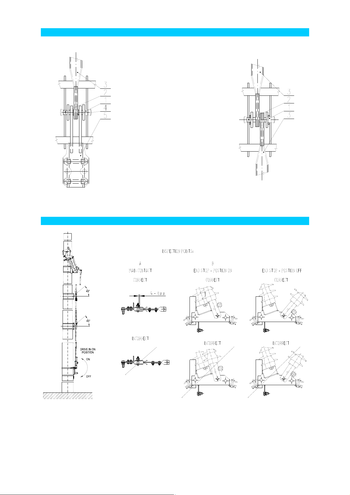
Representation of intermediate bearings
Upper intermediate bearing Lower intermediate bearing
1. Cotter pin 12x63
2. Cotter 4x25
3. Flattened pull rod tube
4. Brass barrel bushing
5. Clamping terminal assembly
Fig. 3a Fig. 3b
Setting and function check
Fig. 4
6
Page 7
Connection of cables, strip leads and earthing
Notice: In the case of connecting the cable on the
fixed insulator side by means of cable eye, a Cu-Al
washer must be inserted between the cable eye and
the connecting lug (under the cable eye).
Strip leads are mounted on the device contacts
straight (in contact axis – see photo). This applies
also to the middle, symmetrical pole of the device.
The middle pole strips are provided with a skew fork
pull rod on the conductor side.
The marked earthing terminal on the disconnector
frame and the device drive is used for the earthing
of disconnector.
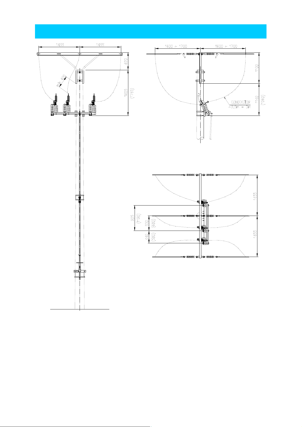
Permitted tilt of the conductors
Detail of connecting strip leads
Permitted tension in conductors: one-side load: 5 kN/conductor
two-side load: 15 kN/conductor
ATTENTION:
It is not allowed to use the load disconnector frame as a support for conductor tightening.
7
Page 8
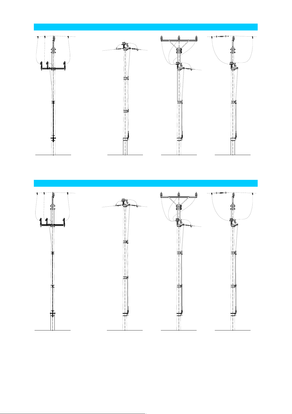
Recommended connection of conductors to the load disconnector –
assembly of the switch below the power line
Dimensions in the brackets apply for Ur = 38.5 kV.
8
Page 9
Installation options of disconnectors series GB R on 10.5m pole
Fig. 5
Installation options of disconnectors series GB R on 12m poles
Fig. 6
9
Page 10

Inspection and maintenance of devices
Outdoor devices Fla 15/60 GB R N and Flc GB R N are disconnectors not demanding for maintenance.
If the disconnector is in switched-off position for a long time (longer than one year), it is recommended making
several no-load manipulations in order to clean the contact joints and to check the mechanical operation of the
drive.
A. In the case of a round once a year – inspection using binoculars:
• Checking visible faults of contacts (burn-offs, distorted contacts).
• Inspection of the condition of insulators.
• Inspection of the integrity of the operating mechanism.
B. In the case of a climbing inspection according to the preventive maintenance plan – at least once for 20 years
(10 years for remotely controlled devices), the following operations must be carried out:
• Check of the correct switching function of the device by switching on and off several times.
• Inspection of the condition of contacts (burn-offs) or replacement, if necessary.
• Check of the correct setting of the device.
• Cleaning contacts with a dissolvent or degreasing agent.
• Lubricating contacts (grease Barrierta L 55/1 from Klüber Lubrikation, Germany).
! CAUTION ! Contacts must not be lubricated with any other grease!
• Check of the run of all bearings and articulated joints and their lubrication (Omnigliss – Spray from Dow
Corning).
• Inspection of insulators for possible damage.
• Cleaning insulators if fouled.
In the case of disconnectors Fla 15/60, an oil condition check is possible. The oil condition check is carried out if
there is a suspicion of oil leakage. At this check, the bleeder plug must only be set, not screwed in. The oil level
must be between the two lines on the bleeder plug gauge. Each quenching chamber contains approx. 0.5 L of oil.
In the case of manually operated disconnectors Fla 15/60 it is recommended, after twenty years, to inspect the
chambers connected with renovation. Renovation is performed at the manufacturer and it includes oil change and
seal replacement, check and, if necessary, replacement of other parts. In the case of remotely controlled devices,
we recommend renovating the chambers due to the anticipated higher operating load after ten years at the latest.
In the case of already renovated quenching chambers, such inspection is recommended after ten years. The
renovation of chambers is performed using the exchange method – in this way the lock-out time is only limited
practically to the time necessary for dismantling old and mounting new chambers.
The same warranty is given to chambers renovated by manufacturer as to new chambers. The
manufacturer also provides free ecological disposal of used oil.
Specifications are subject to change without notice. DRIBO 04/2018
10
 Loading...