

DRIBO Fla 15/60 GB R N, Flc GB R N Instructions For Assembly, Operation And Maintenance
Instructions for assembly,
operation and maintenance
of outdoor load disconnectors
Fla 15/60 GB R N and Flc GB R N
three-pole design
for mounting on concrete pole
rated voltage 25 and 38.5 kV
rated current 400/630 A
1

General
Outdoor devices of Fla 15/60 GB R N and Flc GB R
N series are load disconnectors according to the EN
62271-103 standard. They are manually or motor
operated. Motor drives are designed especially for
remote control.
The GB R N series load disconnectors are universal
devices for mounting into the line (on the top of a
In the Fla 15/60 load disconnectors, disconnecting
takes place in a low-oil volume quenching chamber.
The Flc GB load disconnectors are equipped with a
special sprig quenching mechanism.
The manufacturer does not assume liability for
damage and operating faults caused by not
observing the installation instructions.
pole) or for mounting under the lines (continuous
disconnector or branching).
Climatic conditions
Maximum temperature °C + 40
Minimum temperature °C - 30
Maximum relative air humidity % 100
Maximum wind pressure Pa (m/s) 700 (34)
Maximum ice or hoar-frost thickness mm 20
Typical altitude m a.s.l up to 1000
For use in higher altitudes please consult the manufacturer.
Handling and storage
During transport and handling, disconnectors
may only be lifted at the base frame, never at the
quenching chambers or at the current path or
insulators.
Storage is allowed in both indoor and outdoor
spaces. Store devices on a level surface. Protect
devices against damage during transport and
handling.
List of necessary tools and tightening torques
Tool Size
Ring spanner 24
Engineer’s spanner 24
Socket spanner (GOLA) 17 (16)
Socket spanner (GOLA) 30
Torque spanner – see the table of tightening torques Clamping tongs for stainless fixing band (e.g. Bandimex W 001, Band-It) Stainless fixing band (e.g. Bandimex B 206, Band-It) width 19 mm, thickness 0.75 mm
Clamp for stainless fixing band (e.g. Bandimex S 256, Band-It) width 19 mm
Tool part / joint Torque
Clamping terminal yokes 30 Nm
Connecting lug bolts (power leads) 75 Nm
Device installation on pole
A. Installation of disconnector into the line (on the top of a pole)
The disconnector is installed on a concrete pole using two sleeves R 120 (Fig. 2, pos. 9). The prescribed pole
diameter in the point of fixing the device is 220 – 245 mm.
The upper sleeve is provided with a suspension for the middle conductor.
B. Installation of disconnector under the line (continuous, branching)
The disconnector is installed on a concrete pole using two sleeves R 130 (Fig. 1, pos. 9). The prescribed pole
diameter in the point of fixing the device is 240 – 265 mm.
The disconnector is to be positioned on the support in such a way that the height of the connecting conductor
above the ground at the distance of 2 m to the support was not smaller than 5.5 m with regard to the means of
mechanization which may move around the support point.
2
Installation of drive, intermediate bearings and pull rods
Depending on the fixing height of disconnector, the drive assembly comprises one of two intermediate bearings.
• Only one intermediate bearing is normally used for disconnectors installed under the line (continuous,
branch – for 10.5 m poles.
• Two intermediate bearings are used for disconnectors mounted into the line (on the top of a pole – for
10.5 m and 12 m poles) and for poles mounted under the line (continuous, branching – for 12 m poles).
The first intermediate bearing under the disconnector must be only a pendulum intermediate bearing (with barrel).
The assembly of intermediate bearings can be seen in Fig. 3a and Fig. 3b, respectively.
When assembling and setting the drive, the disconnector is in the switched-on position on the ON stop.
Fix the manual drive T on the concrete pole using the sleeve (Fig. 1 or Fig. 2, pos. 2) at a height of approx. 1350
mm above the ground. Banding the lower part of the drive is done after the complete banding and testing of the
drive function.
Assembling the drive with one intermediate bearing (Fig. 1)
Connect the upper (flattened on both sides) pull rod tube (pos. 7) to the operating lever on the device (pos. 8)
using the pin.
Fix the intermediate bearing (pos. 3) to the lower end of the upper tube. Position the fixing base of the
intermediate bearing to the pole so that the intermediate bearing lever is tilted up at the angle of 45°.
Fix the intermediate bearing in this position to the pole with two bands.
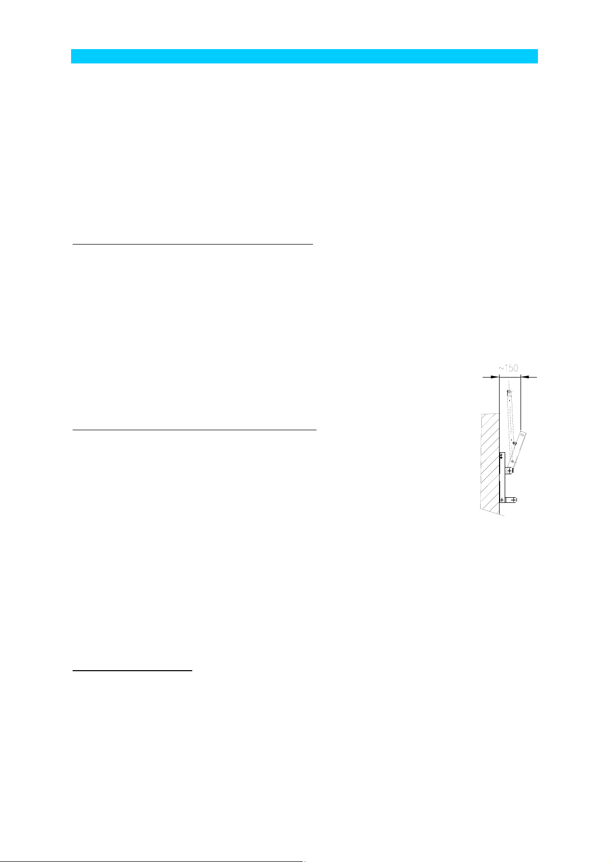
Slide the lower pull rod tube with the end with hole on the socket of manual drive T (pos. 5) and secure with the
provided screw. Move the drive lever to the switched-on position – the lever directs vertically. After swinging the
lever by approx. 150 mm (see the figure; in this way the necessary pretension of the pull rod in the switched-on
position is reached) measure the necessary length of the lower pull rod tube and shorten it. Shorten the tube
from its upper part – the one without holes!
When shortened, screw the lower pull rod tube (pos. 5) together with the manual drive (pos. 1).
Slide the upper end of tube into the yokes of the intermediate bearing (pos. 3) and tighten the
yokes by the prescribed torque.
Assembling the drive with two intermediate bearings (Fig. 2)
Using the pin, fix the upper (flattened on both sides) pull rod tube (pos. 7) to the operating lever
on the device.
Fix the upper intermediate bearing (pos. 3) to the lower end of the upper pull rod tube. Position
the fixing base of the upper intermediate bearing to the pole so that the intermediate bearing
lever is tilted up at the angle of approx. 45° and fix it in this position to the pole with two bands.
Slide the lower pull rod tube (pos. 4) with the end with hole on the socket of manual drive T (pos.
1) and fix with the provided bolt and nut. By means of the pin, fix the lower intermediate bearing
(pos. 4) to the upper end of the lower pull rod tube (pos. 4).
Turn the drive to switched-on position. In this position fix the lower intermediate bearing (pos. 4) with two bands –
after fixing, the intermediate bearing lever must be in parallel with the upper intermediate bearing lever (directing
up at the angle of approx. 45°).
Fix the middle pull rod tube (pos. 6) with the flattened end to the lower intermediate bearing (pos. 4). When tilting
the operating lever of the manual drive (pos. 1) 150 mm from the pole (for the necessary pretension in switchedon position and for elimination of pull rod clearances), measure the necessary length of the middle pull rod tube to
the upper intermediate bearing (pos. 3) and shorten from the upper end.
After shortened, slide the middle pull rod tube (pos. 6) into the yokes of the upper intermediate bearing (pos. 3)
and tighten the yokes by the prescribed torque.
Function test after installation
Operate the drive to the OFF position to disconnect the main contacts. Then operate to the limit ON position. In
the limit ON position, the disconnector must reliably reach the switched-on position (Fig. 4, control points A and
B). Contacts must be fully retracted and the stop on the device must reach the limit position. Intermediate
bearings must not thrust and no deflection of the pull rod tubes must occur (a threat of damage to the drive).
If the limit position of the device is not reached (control point B), make correction by changing the length of the
lower (or middle in the case of the drive with two intermediate bearings) of pull rod tube within the limits of
possible shift on the clamping terminal of the upper intermediate bearing (Fig. 1 and 2, respectively, pos. 3). If a
larger correction is required, the pull rod must be replaced or the drive shifted.
On the disconnector, check that the moving contact is retracted in the main contact properly (Fig. 4, control point
A). If the disconnector does not have the correct clearance in contacts despite reaching the ON position stop,
check that the contact system was not damaged during transport.
3
 Loading...