

Dri-Air Industries ARID-X, HP4-X 18-100 Operating Manual

DRI-AIR INDUSTRIES, INC.
ARID-X & HP4-X 18-100
FLOOR MOUNT DRYERS
OPERATING MANUAL
OPERA TING MANUAL - ARID-X, HP4-X 18-100 FM DR YERS
Revision 10/8/02
Page 1

DRI-AIR INDUSTRIES, INC.
Page 2
DRI-AIR INDUSTRIES, INC.
16 THOMPSON ROAD
P.O. BOX 1020
EAST WINDSOR, CT 06088-1020
Tel. (860) 627-5110
FAX (860) 623-4477
Internet http://www.dri-air.com
e-mail: sales@dri-air.com
OPERA TING MANUAL - ARID-X , HP4-X 18-100 FM DRYERS
Revision 10/8/02

DRI-AIR INDUSTRIES, INC.
CONTENTS
DRYER OPERA TION/FEATURES---------------------------4
AIR FLOW SCHEMA TIC FOR ARID-X DRYERS--------6
AIR FLOW SCHEMA TIC FOR HP4-X DRYERS ---------7
DRYER CYCLE DIAGRAM------------------------------------8
PLC ST ANDARD ELECTRICS -------------------------------9
INST ALLATION PROCEDURE ----------------------------- 10
Electrical Connection ------------------------------------- 10
Check for correct motor rotation ----------------------- 10
START-UP PROCEDURE ----------------------------------- 11
Standard Electrics----------------------------------------- 1 1
To Set Temperature: -------------------------------------- 11
Microprocessor Control ---------------------------------- 12
DRYER OPERATION-TROUBLE SHOOTING --------- 13
DRYER OPERA TION-DETAILED DIAGNOSIS -------- 14
DRI-AIR ROT AR Y ZONE VALVE--------------------------- 15
PARTS LISTS
ARID-X & HP4-X 18 - 35 -------------------------------- 16
ARID-X & HP4-X 50 - 100 ------------------------------ 17
OPERA TING MANUAL - ARID-X, HP4-X 18-100 FM DR YERS
Revision 10/8/02
Page 3

DRI-AIR INDUSTRIES, INC.
DRYER OPERATION/
FEATURES
The ARID-X dryer series is a dual bed design that provides a
constant supply of dry air to the material hopper. While one
bed is removing moisture from the process air the other is
regenerating by heating the desiccant to a high temperature.
Once the regenerated bed cools down, the Zone V alve
switches the airflow, and the newly regenerated bed is used to
desiccate the process air stream. The saturated bed is now
regenerated in the same manner, completing the regeneration
cycle. The cycle is depicted Page 8.
The airflow design of the ARID-X dryers makes the
regeneration cycle more efficient because we utilize a small
amount of the desiccated process air rather than ambient air
to regenerate the desiccant bed. This reduces the impact of
the high moisture content of the ambient air, which would
contaminate the desiccant bed, and allows the dryer to attain
a lower dew point. Please see the Air Flow Schematic on
Page 6.
HP4-X Design
Our patented HP4-X design incorporates 4 desiccant beds
where two are stacked, one over the other. This nearly
doubles the amount of desiccant available for drying the
process air stream, and because of the tower design, the
dryer is able to regenerate the desiccant in the same time as
our ARID-X series. This allows the dryer to operate in very
high humidity conditions without affecting the process air dew
point. In fact, this design produces dew point levels of – 40’ to
-80’ C for faster more complete drying of your material. Please
see the Air FLow Diagram on Page 7.
Page 4
Hopper Design
Dri-Air’s ”all stainless” hopper design utilizes a stainless steel
inner shell surrounded by a stainless steel jacketed insulation
layer. The easily removable stainless steel spreader cone
promotes proper material flow to ensure that the material is
dried efficiently and no dried material is left at the hopper
bottom that needs to be fed out prior to operating. You must
ensure that your hopper is adequately sized for your usage
rate and is kept filled, to ensure that you have sufficient time to
dry the material.
OPERA TING MANUAL - ARID-X , HP4-X 18-100 FM DRYERS
Revision 10/8/02

DRYER OPERATION/
FEATURES (Cont.)
DRI-AIR INDUSTRIES, INC.
Dryer Controls
The ARID-X series can be supplied with the standard PLC
Control Module or the advanced Microprocessor Control
Module, while the HP4-X series is only available with the
Microprocessor Control Module.
The PLC Control module includes a PLC control board,
display board, temperature controller and touch pad that is
programmed for the drying cycle described above. The
controller, display board and touch pad indicate the machine
status, alarms, set points and allow you to enter operational
settings for the dryer. These are explained in more detail later
in this manual.
The Microprocessor Control Module is one of the most
sophisticated yet operator friendly controls on the market. It
has many more features than the PLC control module that
provide the operator with more control and operational
flexibility with the dryer. These features and the operating
instructions are covered in detail in the Microprocessor
Control Instruction Manual included with your dryer.
OPERA TING MANUAL - ARID-X, HP4-X 18-100 FM DR YERS
Revision 10/8/02
Page 5
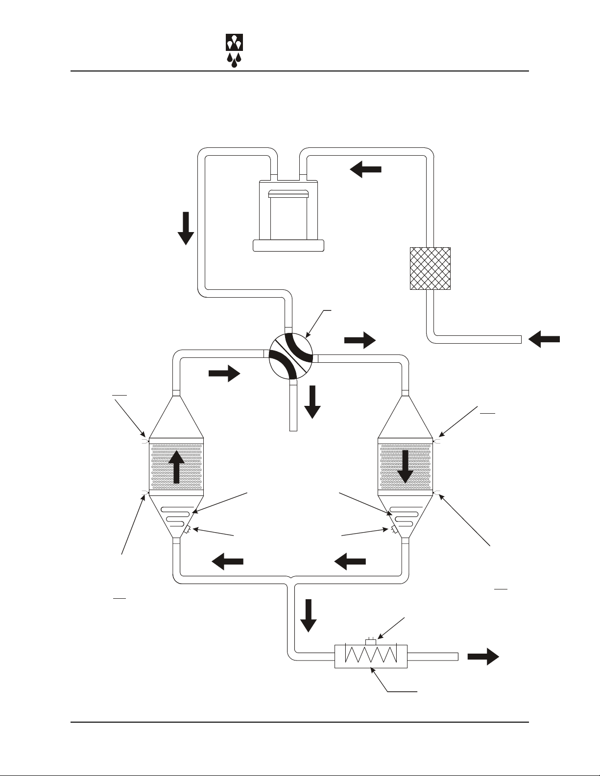
AIR FLOW SCHEMATIC
FOR ARID-X DRYERS
DRI-AIR INDUSTRIES, INC.
CONTROL
THER MOCOU PLE
H1
VORTEX BLOWER
4-WAY ZO NE
VENT
REGENERATION
AND PROC ESS
HEATER
SAFETY THERMAL
VALVE
XX
FILTER
CONTROL
THER MOCOU PLE
H2
CONTROL
THER MOCOU PLE
L1
Page 6
CONTROL
THER MOCOU PLE
L2
SAFETY THERMAL
TO HOPPER
PROCESS HEATER
(APD 5-9)
OPERA TING MANUAL - ARID-X , HP4-X 18-100 FM DRYERS
Revision 10/8/02
 Loading...