

drexel und weiss aerosmart Series, aerosmart S, aerosmart M, aerosmart L Operating, Maintenance And Commissioning
aerosmart S / M / L
Operating, Maintenance and Commissioning


Contents
Technical Data __________________________________________________________2
Customer Information ____________________________________________________3
Product Description ........................................................................................................... 3
Proper Application..............................................................................................................3
Unsuitable Applications...................................................................................................... 3
Safety Instructions ............................................................................................................. 3
Operation _____________________________________________________________4
Micro-Processor Controller ................................................................................................ 4
Main Display ...................................................................................................................... 5
Operating Modes ............................................................................................................... 5
Switching On......................................................................................................................5
Switching Off ......................................................................................................................5
Analogue Room Operating Panel with Heating Mode ....................................................... 6
Digital Room Operating Panel ........................................................................................... 8
Maintenance___________________________________________________________10
Safety Instructions for Filter Changes.............................................................................. 10
Changing Coarse Particle Filters ..................................................................................... 10
Changing the Fine Particle Air Filter ................................................................................ 12
Commissioning ________________________________________________________13
Pre-Requisites for Commissioning .................................................................................. 13
Initial Commissioning ....................................................................................................... 13
Decommissioning ............................................................................................................ 13
Menu levels ___________________________________________________________14
Status Level - Viewing Operating Parameters ................................................................. 14
Technician Level - Setting Operating Parameters ...........................................................16
Manufacturer Level - Factory Settings ............................................................................. 21
Overview – Current Operating Status .............................................................................. 21
Faults ________________________________________________________________22
Error Messages .............................................................................................................. 22
Faults in the Ventilation System.......................................................................................23
Important Unit Information (Logbook) _____________________________________24
Page 1

Technical Data
General Data
Mains supply ...................................................................................... 230 VAC / 50 Hz
Recommended pre-fuse for the mains cable 1 ......................................................16 A
Recommended pre-fuse for the mains cable 2 ......................................................13 A
Heat recovery level
according to VDI 2071 with nominal volumetric fl ow .............................................85 %
Average heat provision level of the ventilation module
Maximum power consumption of the fans (total) .............................................. 100 W
Maximum power consumption of the immersion heater
Operating fl uids:
Refrigerating agent .................................................................................R134a / 2.3 kg
Refrigerating machine oil ........................................................................Triton SEZ 32
aerosmart S
Weight ................................................................................................... approx. 232 kg
Nominal air quantity ........................................................................................120 m
Minimum air quantity .......................................................................................105 m
Maximum air quantity at 100 Pa external ........................................................180 m
Sound power level at nominal air quantity and 100 Pa external:
Housing ..........................................................................................................45 dB(A)
Air inlet ............................................................................................................37 dB(A)
Air vent ............................................................................................................48 dB(A)
.........................................85–93 %
........................................2000 W
3
/h
3
/h
3
/h
aerosmart M
Weight ................................................................................................... approx. 255 kg
Nominal air quantity ........................................................................................160 m
Minimum air quantity .......................................................................................140 m
Maximum air quantity at 100 Pa external ........................................................230 m
3
3
3
Sound power level at nominal air quantity and 100 Pa external:
Housing ..........................................................................................................45 dB(A)
Air inlet ............................................................................................................48 dB(A)
Air vent ............................................................................................................48 dB(A)
aerosmart L
Weight ................................................................................................... approx. 255 kg
Nominal air quantity ........................................................................................205 m
Minimum air quantity .......................................................................................180 m
Maximum air quantity at 100 Pa external ........................................................230 m
Sound power level at nominal air quantity and 100 Pa external:
Housing ..........................................................................................................45 dB(A)
Air inlet ............................................................................................................48 dB(A)
Air vent ............................................................................................................48 dB(A)
3
3
3
/h
/h
/h
/h
/h
/h
Page 2
Customer Information
These operating instructions are part of the unit and must remain with it. This manual contains important notes and tips on operating your compact unit, which protect you from personal injury and
also guarantee a long service life of the unit. The fi gures all depict the right-hand version of the
device (supply air connection located on the right). All instructions are equally applicable to the
left-hand version (supply air connection located on the left). Please keep the operating instructions for future reference. Please pay attention to the safety instructions!
Product Description
The devices in the aerosmart series are compact units which consist of a ventilation
module with heat recovery, a domestic water storage tank and a heat pump. The unit is
used to heat the supply air and the domestic water. The aerosmart S, aerosmart M und
aerosmart L units are operated via a micro-processor controller. Although the unit types
differ in terms of their appearance, weight and managed air quantities, these differences
do not affect their operation.
Proper Application
The unit is designed for the ventilation, heating and warm water generation of living rooms
and lounges in passive houses and, if applicable, for near-passive buildings depending
on the calculation and building design.
Unsuitable Applications
No applications other than those specifi ed under proper application are permissible.
The unit must not be used to dehumidify buildings under construction. Drying and heating
a building structure can cause considerable damage to the unit. The ventilation of rooms
with extremely high humidity levels, such as saunas, or heavily contaminated extract air
is also not permitted.
Safety Instructions
WARNING: Indicates that the non-adherence to the recommended safety
procedures could lead to damage to the unit or personal injury.
CAUTION: Indicates that the non-adherence to the recommended safety procedures could lead to damage to the unit.
NOTE: Helpful information and useful tips.
aerosmart - Operation, Maintenance and Commissioning
Page 3
Operation
The unit is controlled, managed and operated via a micro-processor controller on the unit and a
room operating panel. Two types of room operating panels are available:
•
Analogue room operating panel with heating mode
Digital room operating panel•
If the analogue room operating panel is used, the basic settings must be made on the compact
unit (micro-processor controller) during commissioning.
If the digital room operating panel is used; the settings can all be made on either the room operating panel or the micro-processor controller.
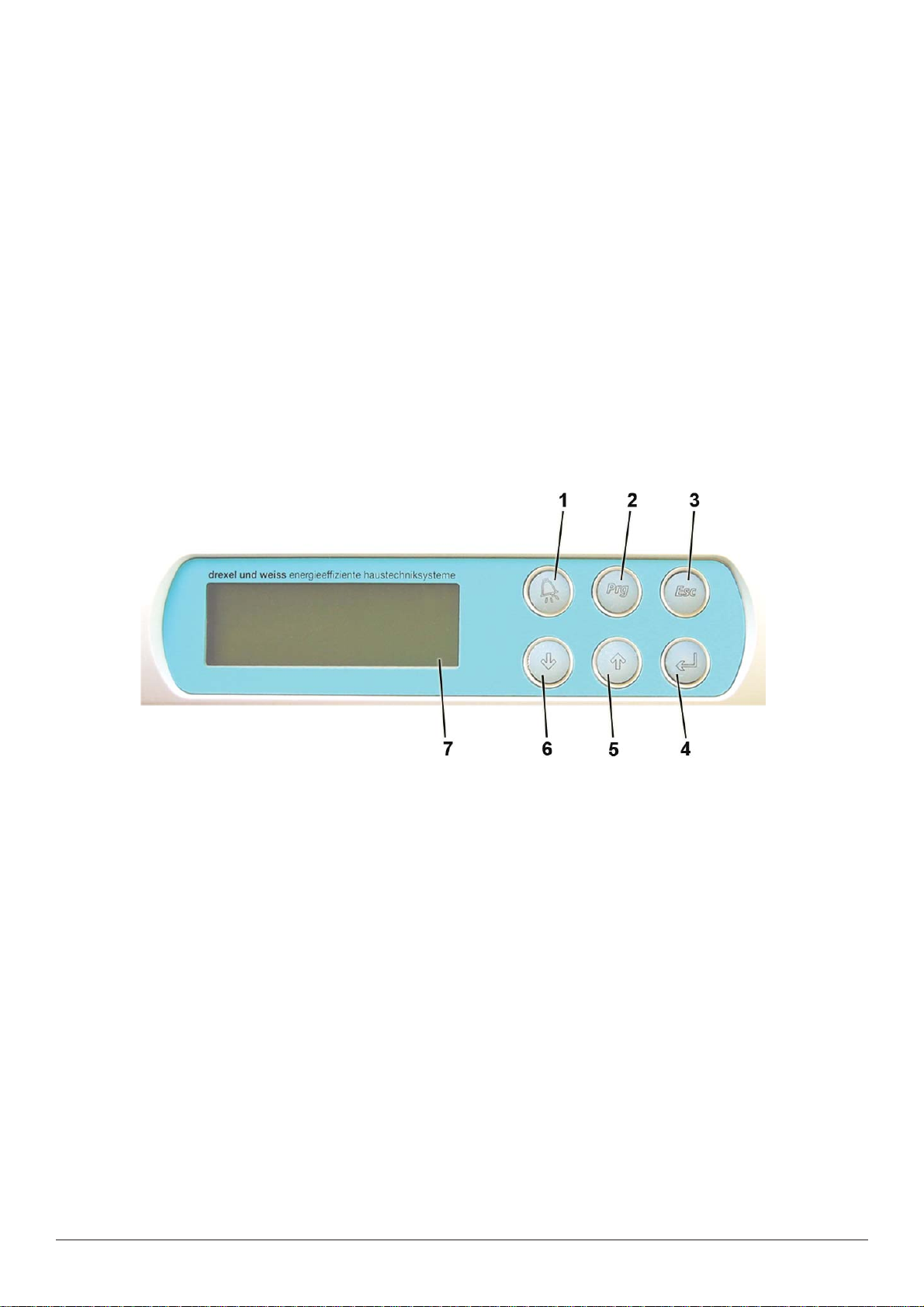
Micro-Processor Controller
The micro-processor controller is located on the ventilation module. It manages the ventilation, room heating and the heating of the domestic hot water.
'Alarm' button: this button illuminates red if the controller transmits an error message. 1.
Press the button to acknowledge the fault.
'Prg' button: is only required to program the software.2.
'Esc' button: use this button to exit a program item or a menu.3.
'4.
↵' (Enter) button: use this button to confi rm selected values, settings or menu items.
'5.
↑' arrow key: for scrolling in the menu. Use this button to select individual menu
items and amend the values.
↓' arrow key: for scrolling in the menu. Use this button to select individual menu
'6.
items and amend their values.
Display: the four-line display shows settings and various measurements.7.
Page 4
aerosmart - Operation, Maintenance and Commissioning

Main Display
The main display shows the time and date, the current operating mode and the current
values for the room, set-point and actual temperature.
12:11 DI. 09/12/03
Akt. Sollwert: 21.5°C
Akt. Raumtemp.: 20.3°C
If you are viewing a different menu page, simply press the 'Esc' button one or more times
to return to this main display.
Operating Modes
AUTOMATIK: all functions are fully automated in this operating mode. Fan levels acc. to programming; water and room heating acc. to the established set-point temperature.
STAND-BY SOMMER: ventilation and heating are deactivated in this operating mode. The
heat pump and the two fans are only activated if the domestic water is heated. An external
switch can be used to switch on the ventilation (or both fans) for an hour, for example, the
light switch in a windowless toilet.
ANLAGE AUSGESCHALTEN: all functions are deactivated.
Press the 'Esc' button until the main display appears.
b
Use the down '↓' or up '↑' arrows to select the desired operating mode.
b
Press '↵' (Enter) to confi rm your selection.
AUTOMATIK
Switching On
Select the operating mode AUTOMATIK.
b
Press '↵' (Enter) to confi rm your selection.
For further information, see Operating Modes.
Switching Off
Select the operating mode ANLAGE AUSGESCHALTEN.
b
Press '↵' (Enter) to confi rm your selection.
For further information, see Operating Modes.
aerosmart - Operation, Maintenance and Commissioning
Page 5
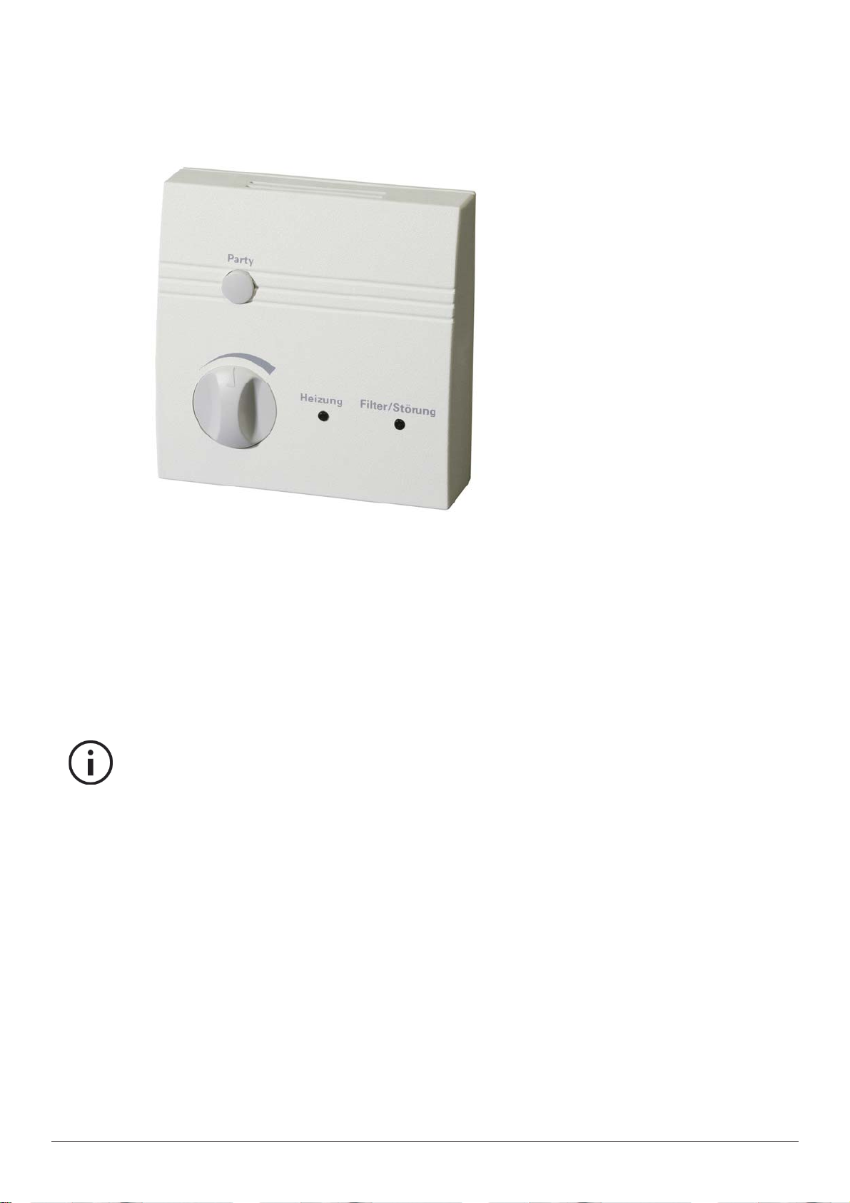
Analogue Room Operating Panel with Heating Mode
Use this room operating panel to set the room temperature and activate the special 'Party'
mode. The LED indicator lights show if the heating is activated and if a fi lter change or
fault is pending.
Setting the Room Temperature
The dial can be used to adjust the set-point temperature by +/- 3°C. On delivery of the
system, the middle setting is 21.5°C.
This means that the temperature can be adjusted from 18.5°C (dial fully to the left) to
24.5°C (dial fully to the right).
Note: Do not turn the dial too far! The left stop point is at approx. 8 o'clock, the right-
hand stop point is at approx. 4 o'clock.
What room temperature is right for me?
The setting basically depends on your needs. Temperature sensitivity in humans is subjective and differs from one person to the next. Standard settings are between 20 and
23°C.
Environmental infl uences
As the room operating panel has a temperature gauge to measure the room temperature,
no heat-emitting devices should be placed beneath it or in its immediate vicinity (e.g. televisions or computers).
Such heat-emitting devices would substantially infl uence the temperature measure-
ments.
Page 6
aerosmart - Operation, Maintenance and Commissioning

A handy hint for greater system effi ciency
If possible, fi nd your desired temperature at the start of the heating period.
The system works most effi ciently if the set-point temperature is set once and then left
unchanged. Regularly changing this setting uses the top up heater in the room more than
necessary.
Special 'Party' Mode
Pressing the 'Party' button sets the ventilation to fan level 3 for a predetermined period.
Once this period has passed, the fan level automatically returns to the currently set level.
On delivery of the system, the default period is 60 minutes, but this can be adjusted on
the micro-processor controller. The special 'Party' mode cannot be reset by pressing the
button again.
Heating (LED)
This indicator light illuminates if the heating mode is enabled.
Filter/Fault (LED)
LED continually illuminated: coarse particle fi lter needs replacing.
Please refer to the 'Maintenance' section.
LED fl ashes: a fault has occurred. The fault type can be viewed on the micro-processor
controller's display screen.
Please refer to the 'Error messages' section.
aerosmart - Operation, Maintenance and Commissioning
Page 7
 Loading...