

drexel und weiss aerosmart Series, aerosmart S, aerosmart M, aerosmart L Operating, Maintenance And Commissioning
aerosmart S / M / L
Operating, Maintenance and Commissioning


Contents
Technical Data __________________________________________________________2
Customer Information ____________________________________________________3
Product Description ........................................................................................................... 3
Proper Application..............................................................................................................3
Unsuitable Applications...................................................................................................... 3
Safety Instructions ............................................................................................................. 3
Operation _____________________________________________________________4
Micro-Processor Controller ................................................................................................ 4
Main Display ...................................................................................................................... 5
Operating Modes ............................................................................................................... 5
Switching On......................................................................................................................5
Switching Off ......................................................................................................................5
Analogue Room Operating Panel with Heating Mode ....................................................... 6
Digital Room Operating Panel ........................................................................................... 8
Maintenance___________________________________________________________10
Safety Instructions for Filter Changes.............................................................................. 10
Changing Coarse Particle Filters ..................................................................................... 10
Changing the Fine Particle Air Filter ................................................................................ 12
Commissioning ________________________________________________________13
Pre-Requisites for Commissioning .................................................................................. 13
Initial Commissioning ....................................................................................................... 13
Decommissioning ............................................................................................................ 13
Menu levels ___________________________________________________________14
Status Level - Viewing Operating Parameters ................................................................. 14
Technician Level - Setting Operating Parameters ...........................................................16
Manufacturer Level - Factory Settings ............................................................................. 21
Overview – Current Operating Status .............................................................................. 21
Faults ________________________________________________________________22
Error Messages .............................................................................................................. 22
Faults in the Ventilation System.......................................................................................23
Important Unit Information (Logbook) _____________________________________24
Page 1

Technical Data
General Data
Mains supply ...................................................................................... 230 VAC / 50 Hz
Recommended pre-fuse for the mains cable 1 ......................................................16 A
Recommended pre-fuse for the mains cable 2 ......................................................13 A
Heat recovery level
according to VDI 2071 with nominal volumetric fl ow .............................................85 %
Average heat provision level of the ventilation module
Maximum power consumption of the fans (total) .............................................. 100 W
Maximum power consumption of the immersion heater
Operating fl uids:
Refrigerating agent .................................................................................R134a / 2.3 kg
Refrigerating machine oil ........................................................................Triton SEZ 32
aerosmart S
Weight ................................................................................................... approx. 232 kg
Nominal air quantity ........................................................................................120 m
Minimum air quantity .......................................................................................105 m
Maximum air quantity at 100 Pa external ........................................................180 m
Sound power level at nominal air quantity and 100 Pa external:
Housing ..........................................................................................................45 dB(A)
Air inlet ............................................................................................................37 dB(A)
Air vent ............................................................................................................48 dB(A)
.........................................85–93 %
........................................2000 W
3
/h
3
/h
3
/h
aerosmart M
Weight ................................................................................................... approx. 255 kg
Nominal air quantity ........................................................................................160 m
Minimum air quantity .......................................................................................140 m
Maximum air quantity at 100 Pa external ........................................................230 m
3
3
3
Sound power level at nominal air quantity and 100 Pa external:
Housing ..........................................................................................................45 dB(A)
Air inlet ............................................................................................................48 dB(A)
Air vent ............................................................................................................48 dB(A)
aerosmart L
Weight ................................................................................................... approx. 255 kg
Nominal air quantity ........................................................................................205 m
Minimum air quantity .......................................................................................180 m
Maximum air quantity at 100 Pa external ........................................................230 m
Sound power level at nominal air quantity and 100 Pa external:
Housing ..........................................................................................................45 dB(A)
Air inlet ............................................................................................................48 dB(A)
Air vent ............................................................................................................48 dB(A)
3
3
3
/h
/h
/h
/h
/h
/h
Page 2
Customer Information
These operating instructions are part of the unit and must remain with it. This manual contains important notes and tips on operating your compact unit, which protect you from personal injury and
also guarantee a long service life of the unit. The fi gures all depict the right-hand version of the
device (supply air connection located on the right). All instructions are equally applicable to the
left-hand version (supply air connection located on the left). Please keep the operating instructions for future reference. Please pay attention to the safety instructions!
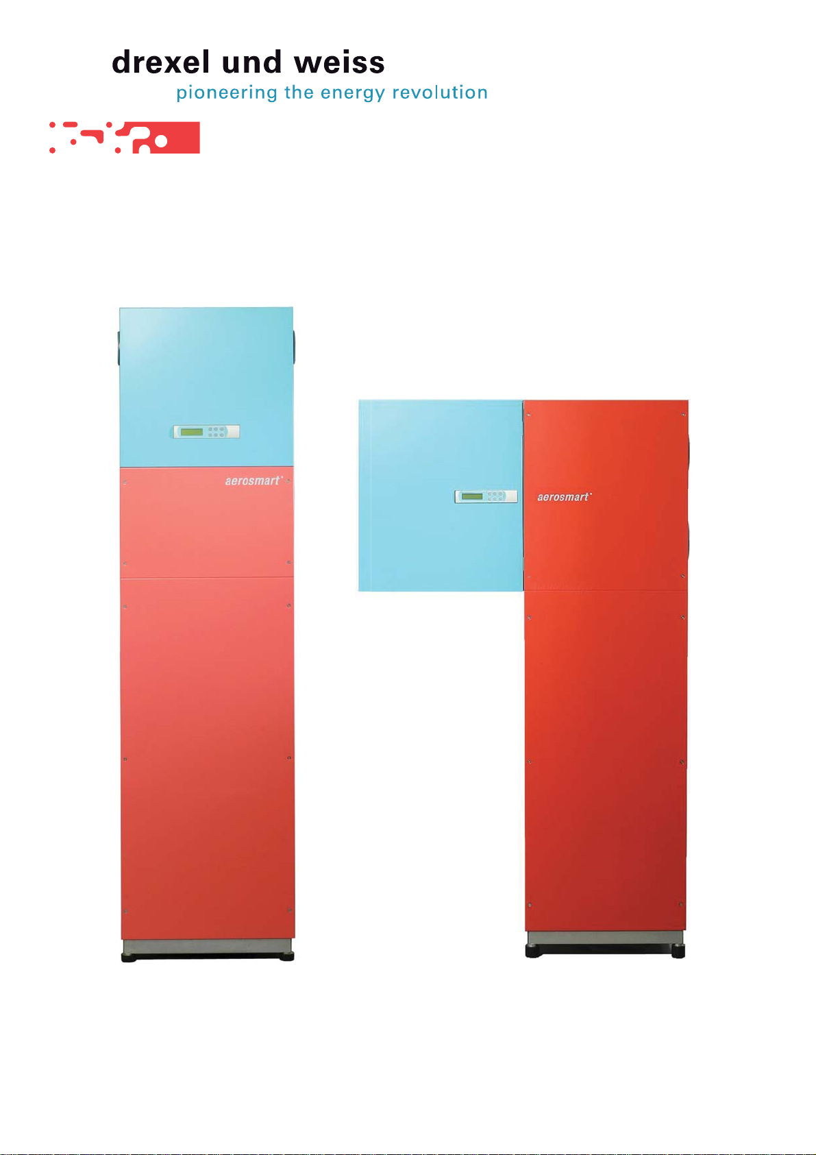
Product Description
The devices in the aerosmart series are compact units which consist of a ventilation
module with heat recovery, a domestic water storage tank and a heat pump. The unit is
used to heat the supply air and the domestic water. The aerosmart S, aerosmart M und
aerosmart L units are operated via a micro-processor controller. Although the unit types
differ in terms of their appearance, weight and managed air quantities, these differences
do not affect their operation.
Proper Application
The unit is designed for the ventilation, heating and warm water generation of living rooms
and lounges in passive houses and, if applicable, for near-passive buildings depending
on the calculation and building design.
Unsuitable Applications
No applications other than those specifi ed under proper application are permissible.
The unit must not be used to dehumidify buildings under construction. Drying and heating
a building structure can cause considerable damage to the unit. The ventilation of rooms
with extremely high humidity levels, such as saunas, or heavily contaminated extract air
is also not permitted.
Safety Instructions
WARNING: Indicates that the non-adherence to the recommended safety
procedures could lead to damage to the unit or personal injury.
CAUTION: Indicates that the non-adherence to the recommended safety procedures could lead to damage to the unit.
NOTE: Helpful information and useful tips.
aerosmart - Operation, Maintenance and Commissioning
Page 3
Operation
The unit is controlled, managed and operated via a micro-processor controller on the unit and a
room operating panel. Two types of room operating panels are available:
•
Analogue room operating panel with heating mode
Digital room operating panel•
If the analogue room operating panel is used, the basic settings must be made on the compact
unit (micro-processor controller) during commissioning.
If the digital room operating panel is used; the settings can all be made on either the room operating panel or the micro-processor controller.
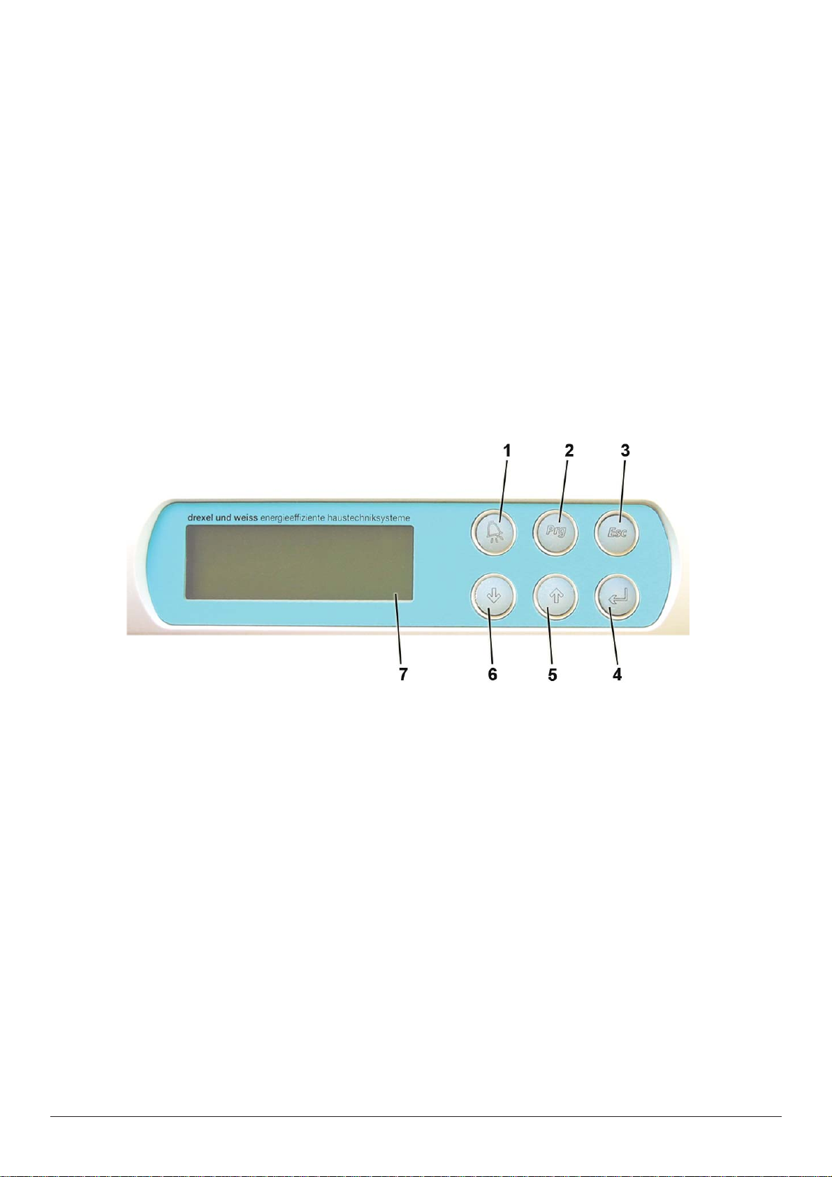
Micro-Processor Controller
The micro-processor controller is located on the ventilation module. It manages the ventilation, room heating and the heating of the domestic hot water.
'Alarm' button: this button illuminates red if the controller transmits an error message. 1.
Press the button to acknowledge the fault.
'Prg' button: is only required to program the software.2.
'Esc' button: use this button to exit a program item or a menu.3.
'4.
↵' (Enter) button: use this button to confi rm selected values, settings or menu items.
'5.
↑' arrow key: for scrolling in the menu. Use this button to select individual menu
items and amend the values.
↓' arrow key: for scrolling in the menu. Use this button to select individual menu
'6.
items and amend their values.
Display: the four-line display shows settings and various measurements.7.
Page 4
aerosmart - Operation, Maintenance and Commissioning

Main Display
The main display shows the time and date, the current operating mode and the current
values for the room, set-point and actual temperature.
12:11 DI. 09/12/03
Akt. Sollwert: 21.5°C
Akt. Raumtemp.: 20.3°C
If you are viewing a different menu page, simply press the 'Esc' button one or more times
to return to this main display.
Operating Modes
AUTOMATIK: all functions are fully automated in this operating mode. Fan levels acc. to programming; water and room heating acc. to the established set-point temperature.
STAND-BY SOMMER: ventilation and heating are deactivated in this operating mode. The
heat pump and the two fans are only activated if the domestic water is heated. An external
switch can be used to switch on the ventilation (or both fans) for an hour, for example, the
light switch in a windowless toilet.
ANLAGE AUSGESCHALTEN: all functions are deactivated.
Press the 'Esc' button until the main display appears.
b
Use the down '↓' or up '↑' arrows to select the desired operating mode.
b
Press '↵' (Enter) to confi rm your selection.
AUTOMATIK
Switching On
Select the operating mode AUTOMATIK.
b
Press '↵' (Enter) to confi rm your selection.
For further information, see Operating Modes.
Switching Off
Select the operating mode ANLAGE AUSGESCHALTEN.
b
Press '↵' (Enter) to confi rm your selection.
For further information, see Operating Modes.
aerosmart - Operation, Maintenance and Commissioning
Page 5
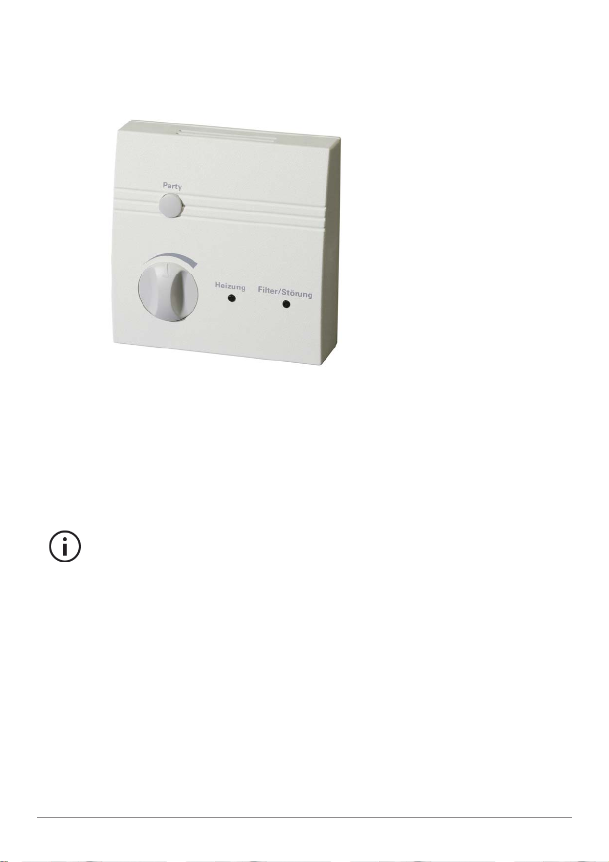
Analogue Room Operating Panel with Heating Mode
Use this room operating panel to set the room temperature and activate the special 'Party'
mode. The LED indicator lights show if the heating is activated and if a fi lter change or
fault is pending.
Setting the Room Temperature
The dial can be used to adjust the set-point temperature by +/- 3°C. On delivery of the
system, the middle setting is 21.5°C.
This means that the temperature can be adjusted from 18.5°C (dial fully to the left) to
24.5°C (dial fully to the right).
Note: Do not turn the dial too far! The left stop point is at approx. 8 o'clock, the right-
hand stop point is at approx. 4 o'clock.
What room temperature is right for me?
The setting basically depends on your needs. Temperature sensitivity in humans is subjective and differs from one person to the next. Standard settings are between 20 and
23°C.
Environmental infl uences
As the room operating panel has a temperature gauge to measure the room temperature,
no heat-emitting devices should be placed beneath it or in its immediate vicinity (e.g. televisions or computers).
Such heat-emitting devices would substantially infl uence the temperature measure-
ments.
Page 6
aerosmart - Operation, Maintenance and Commissioning

A handy hint for greater system effi ciency
If possible, fi nd your desired temperature at the start of the heating period.
The system works most effi ciently if the set-point temperature is set once and then left
unchanged. Regularly changing this setting uses the top up heater in the room more than
necessary.
Special 'Party' Mode
Pressing the 'Party' button sets the ventilation to fan level 3 for a predetermined period.
Once this period has passed, the fan level automatically returns to the currently set level.
On delivery of the system, the default period is 60 minutes, but this can be adjusted on
the micro-processor controller. The special 'Party' mode cannot be reset by pressing the
button again.
Heating (LED)
This indicator light illuminates if the heating mode is enabled.
Filter/Fault (LED)
LED continually illuminated: coarse particle fi lter needs replacing.
Please refer to the 'Maintenance' section.
LED fl ashes: a fault has occurred. The fault type can be viewed on the micro-processor
controller's display screen.
Please refer to the 'Error messages' section.
aerosmart - Operation, Maintenance and Commissioning
Page 7

Digital Room Operating Panel
The digital room operating panel on the ventilation device operates at the same time as
the micro-processor controller. The menu navigation, buttons and scope of operation are
identical.
Setting the Room Temperature
Press the 'ESC' button until the main display appears.
12:11 DI. 09/12/03
AUTOMATIK
Akt. Sollwert: 21.5°C
Akt. Raumtemp.: 20.3°C
b
Press the 'Enter' button. The cursor jumps to the 'Akt. Sollwert'.
b
Use the '↓' and '↑' arrows to set your desired room temperature.
b
Press '↵' (Enter) to save your settings.
What room temperature is right for me?
The setting basically depends on your needs. Temperature sensitivity in humans is subjective and differs from one person to the next. Standard settings are between 20 and
23°C.
Page 8
A handy hint for greater system effi ciency
If possible, fi nd your desired temperature at the start of the heating period.
The system works most effi ciently if the set-point temperature is set once and then left
unchanged. Regular changing of this setting results in the top-up heater in the room being
used more than necessary.
aerosmart - Operation, Maintenance and Commissioning

Special 'Party' Mode
The ventilation is set to fan level 3 for a specifi c period. Once this period has passed, the
fan level automatically returns to the currently set level. On delivery of the system, the
default period is 60 minutes, but this can be adjusted in the technician level.
Press 'Esc' to go from the main display to the main menu.
Technikerebene
Herstellerebene
b
Press 'Enter' to select the 'Statusebene' submenu.
Party-Funktion
Ein mit ENTER:
b
Activate the party function by pressing 'Enter' twice.
b
Press 'Esc' several times to return to the main display.
Statusebene
Übersicht
<STATUSEBENE>
AKTIV
aerosmart - Operation, Maintenance and Commissioning
Page 9

Maintenance
System maintenance by users is mainly limited to regularly changing the coarse particle fi lters
in the ventilation module and the fi ne particle air fi lter in the outside air unit. The operating unit
provides regular fi lter change notifi cations as the system operating hours are counted in the
background. A reminder to change the coarse particle fi lters is displayed approx. every 60-180
days, according to the managed nominal air quantity (depending on the environment and the fi lter
class). The fi ne particle air fi lter only has to be changed approx. once or twice a year. As the fl ow
capacity and acoustic level generated by the compact unit are affected by the amount of dirt in the
fi lters, we recommend that fi lters are changed regularly. No tools are required.
Caution: Possible damage to the unit resulting from dust and contamination. The coarse
particle fi lters in the unit not only improve your air quality, but also protect the entire ven-
tilation system. The system must not be operated without a coarse particle fi lter.
Note: The fi lter should be changed within 2-4 weeks of the 'Filter change' message
appearing..
Safety Instructions for Filter Changes
Caution: The fi lter change intervals are only valid for a completely run-in system. After
the initial commissioning, the fi lters can sometimes become very dirty after a relatively
short time (construction dust). In this case, no error message is displayed.
Caution: Filters cannot be washed or vacuum cleaned as this would drastically affect
their functionality . Contaminated fi lters must always be replaced with clean fi lters. Filters
should be disposed of in the residual waste.
Caution: For uninterrupted operation of the ventilation unit, we recommend that the
system is serviced by an authorised service partner after two operating years. Local
laws and regulations governing maintenance intervals and procedures must be adhered to.
Changing Coarse Particle Filters
Do not switch off the device or unplug it from the mains as the controller will not detect the change
of fi lter .
Page 10
Open the ventilation module's inspection cover.
The cover is held in place by latches and can be removed at the recessed grip. With a slight
tug, without any tools, the cover latches can be released.
b
Remove both fi lter cartridges.
(See fi gure; no. 1+2).
b
aerosmart - Operation, Maintenance and Commissioning

Remove the dirty fi lter pads.
b
Insert new fi lter pads and push the cartridges back into the openings.
Take care with the insertion direction! Ensure that airtightness is guaranteed.
b
Reattach the inspection cover.
Ensure that the cover is properly locked in place.
(Contact switch on the control unit must be activated).
b
Unit starts automatically.
b
After changing the fi lter, press the 'Alarm' button to acknowledge the 'Filter or Filter change'
message on the micro-processor controller.
b
Press '↵' (Enter) to confi rm.
b
Note the fi lter change date in the logbook at the back of this manual.
Fig.: aerosmart S without
inspection cover
Spare fi lter:
Please order the coarse particle fi lters from your authorised technician.
Part description Number
Spare fi lter for aerosmart M/L ..........................................(10 per packet) 193.0200
Spare fi lter for aerosmart S .............................................(10 per packet) 193.0892
aerosmart - Operation, Maintenance and Commissioning
Fig.: aerosmart M
without inspection
cover
Page 11

Changing the Fine Particle Air Filter
y,p y
type. Fo
consid
The fi ne particle air fi lter is located in the outside air unit and not in the compact unit. De-
pending on the composition of the ventilation system, numerous fi lter types can be used. If
the error message 'Change fi ne particle air fi lter' is displayed, replace the dirty fi ne particle
air fi lter (within 2 - 4 weeks) with a new fi lter of the same type. For some
fi lter types, the ventilation direction must be taken into consideration
(marked by an arrow). The fi lter change must be ac- knowledged
on the controller.
Acknowledge Fine Particle Air Filter
Change to the Technician Level on the main menu of the control.
(The English text in the following tables is for representation only and will not be displayed
on the control.)
b
Fig.:
Examples of
external fi lters
<TECHNIKEREBENE>
Bitte beachten Sie
bei Aenderung die
Herstellerangaben!
Press the '↑' (up) arrow button once.
Technician Level
Please consider the
manufacturers details
when making changes!
b
The operating hours counter for the fi ne particle air fi lter appears.
Press the 'Enter' button.
<BETRIEBSSTUNDEN>
FEINSTAUBFILTER
Summe: ######
Reset: N
The cursor jumps to the 'Reset' indicator..
Operating Hours
fi ne particle air fi lter
sum
Reset: No
b
Press an arrow button.
The
'Reset': N indicator changes to Y and the 'Summe' indicator is set to zero.
b
Press '↵' (Enter) to confi rm.
b
Note the fi lter change date in your in the logbook at the back of this manual.
Spare fi lter for the outside air system:
Please order the fi lters for the outside air system from your authorised technician
directly.
Page 12
aerosmart - Operation, Maintenance and Commissioning

Commissioning
Pre-Requisites for Commissioning
The compact unit's water, air, electricity and mechanical connections must conform to the
installation instructions - the boiler must be fi lled with water and the stopcocks must be
opened.
Caution: The unit must not be operated without complete insulation of the air pipes
(exhaust and outside air) as any condensation could damage the individual unit components, such as the electronics or the fans.
Initial Commissioning
Warning: Electrically conductive components can cause serious personal injury! Im-
proper working procedures could damage the unit components. The initial commissioning may only be carried out by technicians authorised by drexel und weiss.
When the controller is powered on for the fi rst time, the controller initially performs a self-
test. The main display then appears.
12:11 DI. 09/12/03
AUTOMATIK
Akt. Sollwert: 21.5°C
Akt. Raumtemp.: 20.3°C
Settings on the Overall System
After initially commissioning the unit, adjust the supply and extract air valve fl ow rates ac-
cording to the planned fl ow rates.
b
Measure and record the air quantities.
Decommissioning
Warning: Serious personal injury can result from improper working procedures.
Decommissioning may only be carried out by suitably qualifi ed and authorised
technicians.
Disconnect all electrical connectors from the unit and remove the water and ventilation
connections in accordance with local safety regulations.
The unit still contains both valuable materials and substances that may not be disposed
of in the residual waste. Please deliver your old unit for recycling to a collection point for
recyclable materials. For operating fl uids, please refer to the 'Technical Data'.
Time Weekday date
automatic
set-point temperature
current room temperature
aerosmart - Operation, Maintenance and Commissioning
Page 13

Menu levels
The individual software areas are divided into levels. Press the 'Esc' button to access the main
menu with the following submenus:
Statusebene
Technikerebene
Herstellerebene
Übersicht
Use the arrow keys to select a sub-menu.
Press 'Enter' to confi rm your selection.
Status Level - Viewing Operating Parameters
All available measurements and settings can be requested in the status level. The values
cannot be adjusted.
Statusebene
Technikerebene
Herstellerebene
Übersicht
Status Level
Technician Level
Manufacturer Level
Overview
Party-Funktion Shows if the party function is enabled
(EVU-Abschaltung) Shows if the energy supply utility shut down is enabled; only
available with double tariff control and when the surge current
cut off is enabled.
Raumtemperatur Current room temperature (measured by the gauge in the ana-
logue room operating panel or in the external gauge housing).
Temp. Boiler Unten Domestic water temperature in the lower region of the storage
tank.
Temp. Boiler Mitte Domestic water temperature in the middle region of the storage
tank.
Temp. Verdampf.block Current temperature in the heat pump's evaporator block.
Heizen Stufe 1 If the room thermostat requests “heating level 1”, 'YES' appears
here. If no cut-off is enabled (DW priority), the supply air is
heated in the aerosmart.
Heizen Stufe 2 If the room thermostat requests “heating level 2”, 'YES' appears
here. The external room heating is also enabled (start-up and
shut-down delays apply for pellet stoves)
Verdichter Current status of the compressor
MV - Fluessig Current status of the liquid solenoid valve
Page 14
MV – Heissgas Current status of the hot gas solenoid valve
MV – Luft Current status of the solenoid valve for the air capacitor
Zusatzheizung Current status of the top-up heater in the room
aerosmart - Operation, Maintenance and Commissioning

Anf. Heizstab Current status of the (optional) immersion heating element in
the boiler
Boilergrenztemp. Überwachung
The boiler is monitored for overheating. Temperature above
68°C = level 1; temperature above 73°C = level 2 (see error
messages Übertemperatur Boiler WP aus -
perature boiler heat pump off
).
Excess tem-
Aktuelle Stufe Current fan level (0/1/2/3)
Aktuelle Luftmenge Current air quantity in m³/h
Gerätetype Displays the unit type and the current software version.
aerosmart - Operation, Maintenance and Commissioning
Page 15

Technician Level - Setting Operating Parameters
All operation-related settings are made in the technician level. Use the arrow buttons to
scroll through the individual parameters on the menu pages. The cursor always fl ashes
on the value to be amended.
Statusebene
Technikerebene
Herstellerebene
Übersicht
Selecting the Room Operating Panel
<TECHNIKEREBENE>
Bitte wählen Sie Ihr
Raumbediengerät aus:
Technician Level
Please select your
room operating panel:
ANALOG ANALOG
Select the type of your operating unit (analogue or digital).
Press '
↵ ' (Enter) to confi rm.
Setting the Domestic Water Temperature
<TECHNIKEREBENE>
BW-Sollwert: 42.0°C
Zyklisch Aufheizen: N
Beginn: 04:00
Technician Level
Domestic water set-point
Cyclic heating process: No
Start
BW-Sollwert
The DW set-point (domestic water set-point) can be set from 37°C to 50°C. If, for example,
the set-point is set at 42.0°C, domestic water heating is enabled as soon as the temperature
in the lower area of the boiler (actual value) falls below this point. On reaching 47.0°C, i.e.
5°C above the set-point, the domestic water heating process is switched off again.
What domestic water temperature is right for me? The usual domestic water temperature is
36-38°C for showering, 37 to 42°C for having a bath and 40 to 45°C for washing dishes. Depending on the temperatures you are used to, we recommend a DW set-point temperature
of between 38 and 48°C.
Page 16
Note: If no warm water is removed for an extended period during the heating period, the do-
mestic water temperature can exceed the predetermined set-point.
Zyklisches Aufheizen
This parameter makes it possible to regularly heat domestic water to 60°C. (immersion heater must be switched on).
The function is regionally stipulated by the legislator (e.g. Switzerland) and is normally not
required.
J = Yes
N = No
Beginn
This setting is used to determine when the cyclic heating process is started. The time set
here is usually one at which a reduced rate electricity tariff is available.
aerosmart - Operation, Maintenance and Commissioning

Setting the Default Set-Point Room Temperature
Stnd. Sollwert: 21.5°C
Akt. Sollwert: 20.3°C
Nachtabsenkung: 0.0°C
Von/Bis: 22:00/06:00
Standard set-point temperature
Set-point temperature
Reduced set-point temperature
From/ To:
Stnd. Sollwert
When using the analogue room operating panel, the user can turn the dial to adjust the room
set-point temperature by +/- 3°C. The middle dial setting is programmed. The default setpoint can lie between 18 and 24°C.
Note: This option is not available when using the digital room operating panel as the de-
sired temperature is directly programmed on the room operating panel.
Akt. Sollwert
Current set-point: air temperature measured by the room gauge. This value cannot be adjusted.
Nachtabsenkung der Raumsolltemperatur
This can be used to reduce the room set-point temperature for a freely defi nable period of
the day (Default set-point) by up to 5°C.
Von/Bis: 22:00/6:00
Enter the time period for the reduction of the room set-point temperature.
Room Heating Cut-Off
This function can be used to briefl y disable the room heating if the temperature in the
domestic water storage tank falls below a specifi c level. During the cut-off, the heat pump
is only used to heat the domestic water. Two menu pages are available to set the room
heating cut-off:
<TECHNIKEREBENE>
Fühlerwahl für
Sperre Raumheizung
BOILERTEMP.MITTE
This parameter determines the temperature gauge used for the room heating cut-off. If there
is a high level of warm water usage, this parameter can be set to 'BOILERTEMP.UNTEN'.
Technician Level
Temperature gauge for
Room heating cut-off
Middle boiler temp.
BOILERTEMP.UNTEN Lower boiler temperature
BOILERTEMP.MITTE Middle boiler temperature
aerosmart - Operation, Maintenance and Commissioning
Page 17

<TECHNIKEREBENE>
Sperre Raumheizung
Soll: 35°C
Diff: 07.0°C
Technician Level
Room Heating cut-off
Set
Difference
Soll
By increasing the set-point, the warm water comfort can be increased.
Diff
The 'Difference' value describes the hysteresis, the exceeding of which deactivates the room
heating cut-off.
Setting the Nominal Air Quantities
<TECHNIKEREBENE>
Nennluftmenge:
Technician Level
Nominal air quantity
### m3/h
(Lüfterstufe 2)
This parameter is used to program the system's nominal air quantity. Please refer to the
house technology planning for the value to be set.
(fan level 2)
Note: It is only necessary to enter the nominal air quantity for fan level 2. The air quantities for levels 1 and 3 are automatically defi ned with -30% (level 1) and +30% (level 3).
Timeframe for Fan Control
There are two available menu pages for the temporal programming of the fans. The default level is fan level 2, which does not have to be programmed. This level always applies
when no timeframe is enabled.
Zeitprogramm 1
Lüfterstufe: 1
Beginn: 00:00
Ende: 00:00
Time program 1
Fan level
Start
End
Page 18
For example, program a timeframe for fan level 1 for the time of day at which the house is
usually empty.
Zeitprogramm 2
Lüfterstufe: 3
Beginn: 00:00
Ende: 00:00
You can also program a timeframe for fan level 3, for example, for fi xed cooking times.
Time program 2
Fan level
Start
End
Note: You can set two time programs for fan level 1 or two time programs for
fan level 3.
aerosmart - Operation, Maintenance and Commissioning

Setting the Time and Date
Uhr neu einstellen
Zeit: 00:00
Datum: 01/01/00
Wochentag: SO.
This window can be used to set the time and date.
MO. = Monday
DI. = Tuesday
MI. = Wednesday
DO. = Thursday
FR. = Friday
SA. = Saturday
SO. = Sunday
Setting the Time Period for the Party Mode
<TECHNIKEREBENE>
Laufzeit für
Party-Funktion:
60 min Status: Ein
Set clock
Time:
Date: day/month/year
Weekday:
Technician Level
Time period for the
Party mode
status
Use this window to set the time period for the 'Party' mode. The default value is 60 minutes;
values between 10 and 99 minutes can be entered.
Ein = On
Aus = Off
External Filters
<TECHNIKEREBENE>
Aussenfi lter: Ja
Use this window to enter whether your system has a fi ne particle air fi lter (usually in front of
the ground source heat exchanger in the external area). If so, the controller issues regular
fi lter change reminders (1 x year).
Ja = Yes
Nein = No
Technician Level
Outside air fi lter: Y es
Top-up heater
<TECHNIKEREBENE>
Pellet- o. Stückholz:
Nein
Technician Level
Pellet or Log stove
No
Use this window to enter whether a top up heater is used in the form of an ambient-air dependent pellet or log stove. If so, a special safety switch is used to deactivate the extract air
fan if the supply ventilator fails, to prevent any low-pressure in the room.
aerosmart - Operation, Maintenance and Commissioning
Page 19

Operating Hours Counter
For control, service and maintenance purposes, various operating hours for individual
operations can be viewed here.
J = Yes
N = No
<BETRIEBSSTUNDEN>
VERDICHTER
Summe: 00000 STD.
Reset: N
<BETRIEBSSTUNDEN>
Raumheizungsstufe 1
Summe: 00000 STD.
Reset: N
<BETRIEBSSTUNDEN>
Raumheizungsstufe 2
Summe: 00000 STD.
Reset: N
<BETRIEBSSTUNDEN>
Grobstaubfi lter
Summe: 00000 STD.
Reset mit Türkontakt
Operating Hours
Compressor
Sum: 00000 hours
Reset: No
Operating Hours
Room heating level 1
Sum: 00000 hours
Reset: No
Operating Hours
Room heating level 2
Sum: 00000 hours
Reset: No
Operating Hours
Coarse particle fi lter
Sum: 00000 hours
Reset with door contact switch
<BETRIEBSSTUNDEN>
Feinstaubfi lter
Summe: 00000 STD.
Reset: N
Operating Hours
Fine particle air fi lter
Sum: 00000 hours
Reset: No
Page 20
aerosmart - Operation, Maintenance and Commissioning

Manufacturer Level - Factory Settings
Statusebene
Technikerebene
Herstellerebene
Übersicht
This menu can be used to set the factory parameters. If needs be, these parameters can
be changed by the authorised customer service agents. A password is therefore required
to access the menu.
Overview – Current Operating Status
This menu provides a quick overview of the current operating status.
Statusebene
Technikerebene
Herstellerebene
Übersicht
Tr: 14.0°C Verd.: 1
Tb:-04.4°C MV-FL: 1
Tu: 34.4°C MV-HG: 0
Tm 34.4°C MV-LU: 1
Tr Current room temperature measured by the sensor on the control unit or
an external room sensor
Tb Temperature on the heat pump evaporator register
Tu Current temperature in the lower area of the boiler. Depending on this
temperature, the heat pump is activated.
Tm Current temperature in the middle area (centre) of the boiler. Depending
on this temperature, the domestic water heating can be given priority and
the room heating can be temporarily disabled by the heat pump.
Verd. Current status of the compressor or the heat pump
MV-FL Current status of the liquid line's solenoid valve. This valve is only closed
at the start of thawing; it otherwise opens when the compressor operation
starts.
MV-HG Current status of the hot gas line's solenoid valve. It is open during the
compressor's start phase (unloaded start) and during the thaw process.
MV-LU Current status of the air capacitor line's solenoid valve. Air heating is ena-
bled when this valve is open.
aerosmart - Operation, Maintenance and Commissioning
Page 21

Faults
Error Messages
The messages described here are displayed on both the micro-processor controller and
the digital room operating panel. The faults cannot be acknowledged until they have been
resolved. If several faults occur simultaneously, use the up
to scroll through the error messages.
If a fault cannot be acknowledged by holding down the Enter button (2 sec), please contact your customer service technician.
Warning: Electrically conductive components can cause serious personal injury! Improper working procedures could damage unit components. The inner inspection cover
may only be opened by authorised technicians.
Alarm Niederdruck-Pressostat:
Check if the air quantity is too low due to a closed air line. (E.g. very dirty exhaust air fi lter,
contaminants in the air line).
The following operating conditions are not permissible for the heat pump: room temperature
too low; outside air entrance temperature from the ground source heat exchanger too low;
lack of cooling agents
'↑' and down '↓' arrow buttons
Alarm Hochdruck-Pressostat:
Air quantity too low. The heat cannot be dispersed via the air. (E.g. minimum air quantity set
too low, frozen outside air grid in winter)
Zuluftventilator ausgefallen / Abluftventilator ausgefallen
A valve has failed. If the fault cannot be acknowledged by holding down the Enter button
(2 sec), please contact your customer service technician.
Blocktemperatur zu tief
The following operating conditions are not permissible for the heat pump: room temperature
too low; outside air entrance temperature from the ground source heat exchanger too low;
block gauge faulty; extract air fan faulty or dirty.
Low air quantity and very damp extract air
Closed extract or exhaust air line
Fühlerfehler Verdampfer / Boiler unten / Mitte
Temperature gauge/cable faulty / connector loose; all the system's temperature gauges are
monitored. If the lead to a sensor is disconnected, a gauge provides meaningless values
or a short-circuit occurs, a relevant error message is issued and an emergency program is
enabled.
Übertemperatur Boiler Wärmepumpe aus
1. Storage tank temperature above 68°C - unit automatically switches to fan level 3; blocked
supply air fi lter or fi ne particle air fi lter, authorised technicians to check ground source heat
exchanger.
2. Storage tank temperature above 73°C - storage tank overheats, system switches off;
shortly after the initial commissioning (approx. 20 minutes), check if the DW storage tank is
fi lled with water. If necessary, fi ll the DW storage tank with water.
While heating the building envelope; if no warm water has been taken from the DW storage
tank for a long time. Remove warm water.
If the fault reoccurs within a short timeframe, check if the coarse particle fi lter and the fi ne
particle air fi lter have become extremely dirty (possibly through construction dust). If the fault
reoccurs, contact customer service technician.
Page 22
aerosmart - Operation, Maintenance and Commissioning

No Link (or no text in the digital room operating panel)
Fault with addressing the digital room operating panel; the digital room operating panel is
already correctly addressed on delivery. It is, however, possible that the message 'No link'
appears after commissioning or changing the room operating panel. To create a link to the
micro-processor controller, the address must be corrected on the operating panel:
Hold down the '↓', '↑' and '↵' buttons at the same time until the text: '
SETTING' appears.
DISPLAY ADDRESS
b
Confi rm your selection by pressing '↵' (cursor fl ashes on the address)
b
Use the '↓', '↑' arrows to set the correct address (I/O board address 00: display address: 00
or I/O board address 01: display address: 32)
b
Confi rm the new value by pressing '↵'.
The following message appears: 'DISPLAY ADDRESS CHANGED'
b
The room operating panel now has the correct address and operates alongside the microprocessor controller in the ventilation unit.
Other
The display shows 'Automatik' but the compressor is not operating; Press '↵' (Enter) to
confi rm the operating mode change. T o check this fault, press 'Esc' twice. The current operat-
ing mode will appear on the display.
After a fi lter change: check if the inspection cover is fully closed (contact switch).
Automatik Automatic mode
Faults in the Ventilation System
Noises
The unit is becoming louder by the day since its initial commissioning: exhaust air fi lter / sup-
ply air fi lter very dirty - fans working at an increased speed to try to achieve the minimum air
quantity. Check the condition of all fi lters.
Unit becomes louder during operation: impermissible resistance in an air line (e.g. contaminant blocking air inlets, outside air inlet frozen over in winter)
aerosmart - Operation, Maintenance and Commissioning
Page 23

Important Unit Information
(Logbook)
Your authorised technician has handed over the unit to you with the following settings. Please
keep this data handy in case of queries.
Customer:
Location:
Unit type / version:
Serial number:
Initially
commissioned on:
Installation company:
Authorised
technician:
Set
air quantity (m³/h)
Time program 1 Fan level Start End
Time program 2 Fan level Start End
Filter change
(Date):
Maintenance (Date):
Page 24
aerosmart - Operation, Maintenance and Commissioning

aerosmart - Operation, Maintenance and Commissioning
Page 25

Legal notice
Publisher:
drexel und weiss energieeffi ziente
haustechniksysteme gmbh.
Achstrasse 42, 6922 Wolfurt
T 05574 47895-0
F 05574 47895-4
E-mail: offi ce@drexel-weiss.at
www.drexel-weiss.at
ATU 35542007; FN 192604t;
Company Accounts Registrar: Feldkirch
Document number: 20080908.01 BWI-EN
 Loading...