

OPERATION MANUAL TLS-LM can be downloaded from the website below.
http://www.drexelbrook.com/Continuous-Level-Measurement/Index.aspx
Unpacking the Rigid Level Sensor
IMPORTANT
Be sure to read and understand all of the Installation Instructions before beginning the procedure!
Unpacking
Carefully remove the contents of the shipping carton and check each item against the packing list before destroying any
packing materials. If there is any shortage or damage, report to the factory at 1-215-674-1234.
Storage
Tank Level Systems should be stored in their original shipping containers until ready for installation. Damage that occurs in
storage is not covered under manufacturer’s system warranty.
o CAUTION! DO NOT BEND RIGID LEVEL SENSORS: ANY RESULTING PERMANENT DAMAGE IS
CONSIDERED USER DAMAGE, AND IS NOT COVERED UNDER WARRANTY.
o LONGER RIGID LEVEL SENSORS NEED TO BE SUPPORTED AT BOTH ENDS WHILE HANDLING.
o DO NOT ATTEMPT TO OPEN RIGID LEVEL SENSOR, OR ATTEMPT TO WELD ITS TUBING.
RIGID LEVEL SENSOR INSTALLATION AND HANDLING PROCEDURE
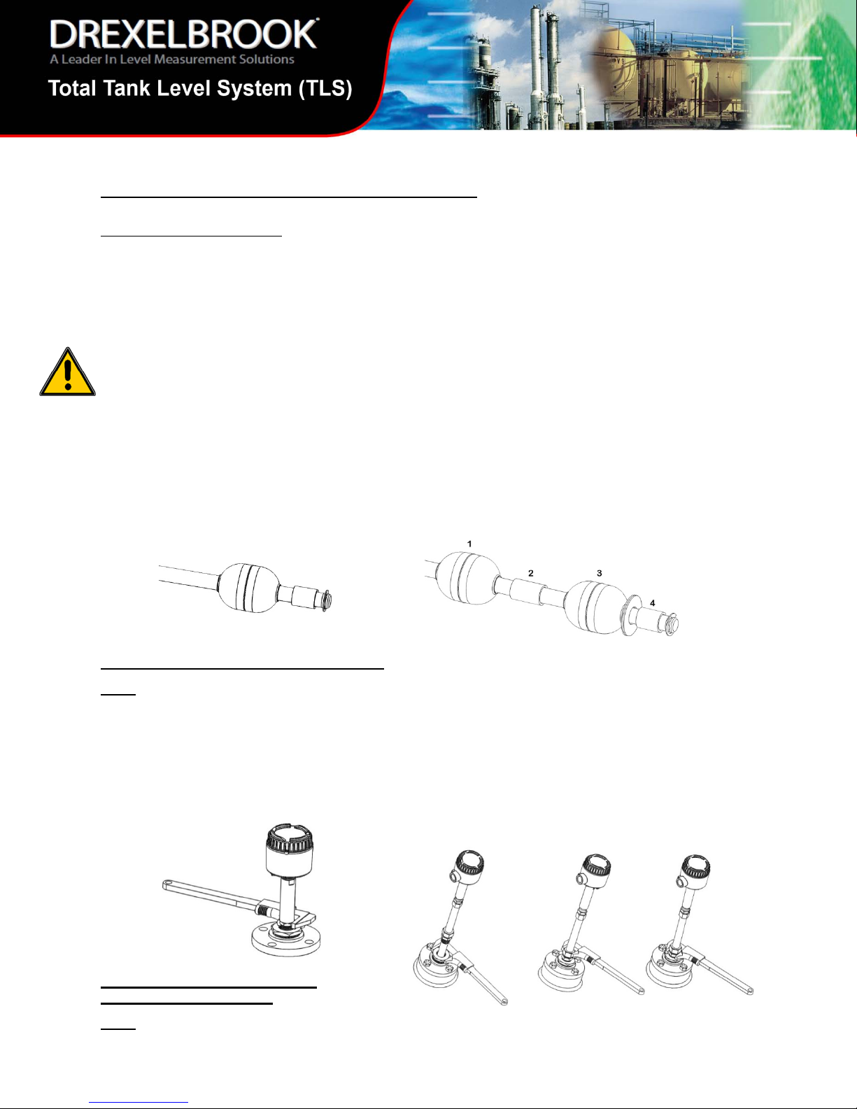
Level Sensor Assembly (B style)
If required, install the compression fitting and reducer bushing (not shown – user supplied) onto level sensor tubing. Then
install floats and spacers on the end of the level sensor as shown.
ONE FLOAT requirement: Install the float, dead band spacer, and retaining fastener (“e-clip”).
TWO FLOAT requirement: Install as follows: “Product” float (1), interposing spacer (2), “Interface” float (3), dead band
spacer (4), and retaining fastener (“e-clip”).
Sensor Installation – Standard Fitting style
NOTE: The Rigid Level sensor in this style requires a
minimum tank bottom clearance of 1/2”. Tank bottom
clearance is defined as the distance from tank bottom
surface to the tubing plug on level sensor.
STEP 1: Lower the level sensor tube (with required floats
and spacers) through opening on tank flange, and into tank.
STEP 2: Thread and tighten the ¾”NPT fitting on probe
tubing into tank flange.
Sensor Installation – Adjustable
Compression Fitting style
NOTE: The Rigid Level sensor in this style requires a
minimum tank bottom clearance of 1/2”. Tank bottom
clearance is defined as the distance from tank bottom
surface to the bottom of the tube on the level sensor.
STEP 1: Lower the lever sensor tube (with required floats
and spacers) through opening on customer tank flange, and
into tank.
STEP 2: Thread and tighten user supplied reducer bushing
into tank flange.
STEP 3: Thread and tighten lower ¾”NPT half of
compression fitting into reducer bushing on tank flange.
STEP 4: Adjust level sensor to desired tank depth
(reference chart below), and hand tighten compression fitting
into reducer bushing on tank flange. After hand tightening,
turn the fitting 1-1/4 turns. Do not over tighten.
STEP 2 STEP 3 STEP 4
Level Sensor Assembly (F and S style)
FLOAT Installation: Install the float with retaining fastener (“e-clip”) for the “F” style probe and install the float with retaining
fastener (“R-clip”) for the “S” style probe as shown.
“F” style probe with (“e-clip”) “S” style probe with (“R-clip”)
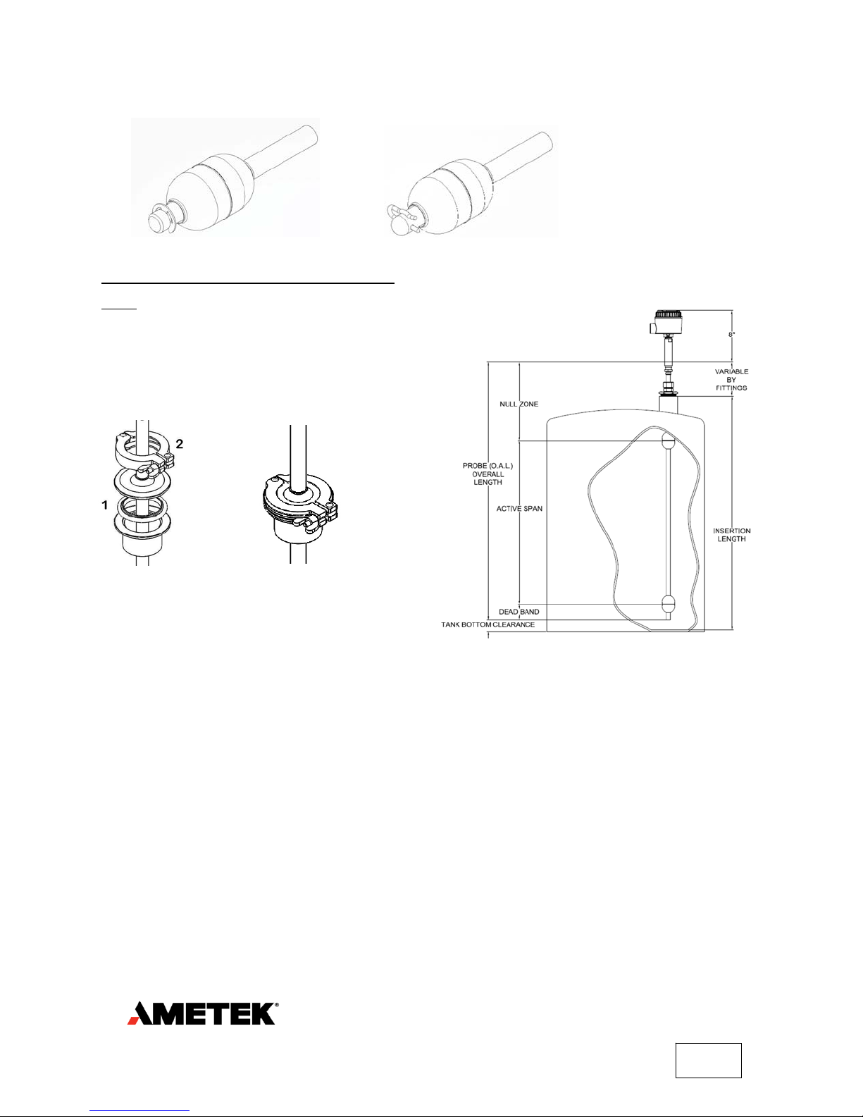
Sensor Installation – Tri-Clamp Flange style
NOTE: The Rigid Level sensor in this style requires a
minimum tank bottom clearance of 3/8”. Tank bottom
clearance is defined as the distance from tank bottom
surface to the bottom of the tube on the level sensor.
STEP 1: Install O-ring assembly (1).
STEP 2: Mount level sensor with clamp assembly (2) as
shown.
COMPLETED ASSEMBLY
Telephone: +1 215-674-1234 or e-mail: drexelbrook.info@ametek.com
Fax: +1 215 674-2731:
© 2015, by AMETEK, Inc. All rights reserved. Printed in the U.S.A.
Specifications are subject to change without notice. Visit our Web site for the most up-to-date information.
An ISO 9001 Certified Company
NOTE: Extreme temperatures have an effect on level sensor
length. In high temperatures, level sensor length will
expand. In low temperatures, level sensor length will
contract.
MINIMUM TANK BOTTOM CLEARANCES:
“B” style: 1/2”, “F” and “S” style: 3/8”
| 205 Keith Valley Road | Horsham PA 19044 U.S.A.
TLS.I0R
10/15.Z421
 Loading...