

DREXAN 10CMH277, 15CMH277, 5CMH120, 20CMH240, 15CMH208 Installation Instructions Manual
...
Page 1 of 6
HD140401-1 Rev 2
Part No. DREX0074
These installation instructions are only for use with the following
Drexan HeatTracer Self-Regulating heater products: PipeGuard® CMH
This kit may be installed in temperatures as low as -40°F/-40°C.
APPROVALS
Class I, Div. 1/2, Groups A, B, C, D
Class II, Div. 1/2, Groups E, F, G
Class III
231572
Installation Instructions
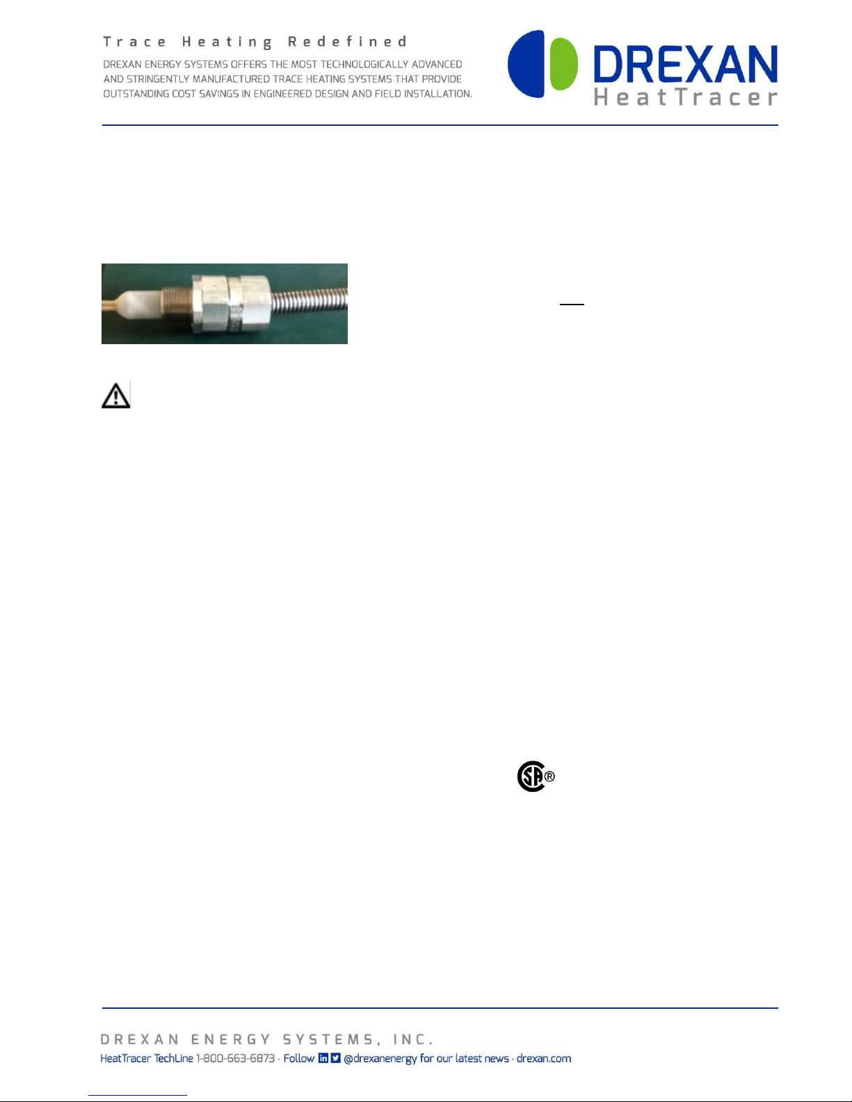
CMH-CON
CMH - Connect
WARNING: This is an electrical device and in order to ensure proper operation and prevent shock or fire it must
be installed correctly. Read these important warnings. Follow all installation instructions.
CAUTION: Ground-fault equipment protection must be used to minimize the danger of fire from sustained electrical
arcing if the heating cable is damaged or improperly installed and to comply with Drexan requirements, agency
certifications and national electrical codes. Conventional circuit breakers may not stop arcing. The metal sheath of
CMH heating cable shall be grounded, but shall not be used as the grounding means.
Metallic structures or materials such as metal pipes used to support CMH cable shall be grounded.
CMH Cable is not to cross or come in contact with itself.
CMH heating cables are to be thermostatically controlled.
Component approvals and performance characteristics are based on Drexan specific parts only.
Substitution will void approvals and performance claims.
Component and heating cable ends must be kept dry before and during installation.
Fire resistant thermal insulation should be used.
CMH cable may be terminated or spliced in any certified enclosure mounted off the heated surface.
120 – 277 Volt. 30 W/ft. max., Maximum withstand temperature 450˚C power off
Drexan Energy Systems, Inc.
Kelowna, BC, Canada, V4V 1S5
CMH Connect Installation Instructions
CMH-CON
Page 2 of 6
HD140401-1 Rev 2
Part No. DREX0074
(2) Strain Relief Fittings (with grommets and washers)
(2) Heat Shrink Sleeves
(2) Silicone Boots
(2) Silicone Boots (for end seal only)
(2) ¾” Sealing Rings (use with HP-BRAK, bottom entry)
Installation Instructions
(2) #2 Anti-short Bushings (optional accessories)
Silicone RTV Sealant
Materials
Pipe straps
Thermostat
Junction Box
Equipment
HP-BRAK bracket
Fine tooth hacksaw
Pipe wrench
CMH Stripping Tool
Electrical Tape
KIT CONTENTS
REQUIRED BUT NOT PROVIDED
I. ASSEMBLY INSTRUCTION DETAILS
Note: CMH cable may be terminated in any enclosure certified for the application.
When using a non-metallic enclosure use a hub with a grounding lug.
1. Megger the insulation resistance between the sheath and conductors. The reading should be 20 MOhm or higher
prior to installing the cable. After thermal insulation is installed on the pipe ensure the megger reading is 5 MOhm
or higher
Note: CMH Cable is a zone type cable. Refer to CMH Cable Reference Chart at the back of these instructions.
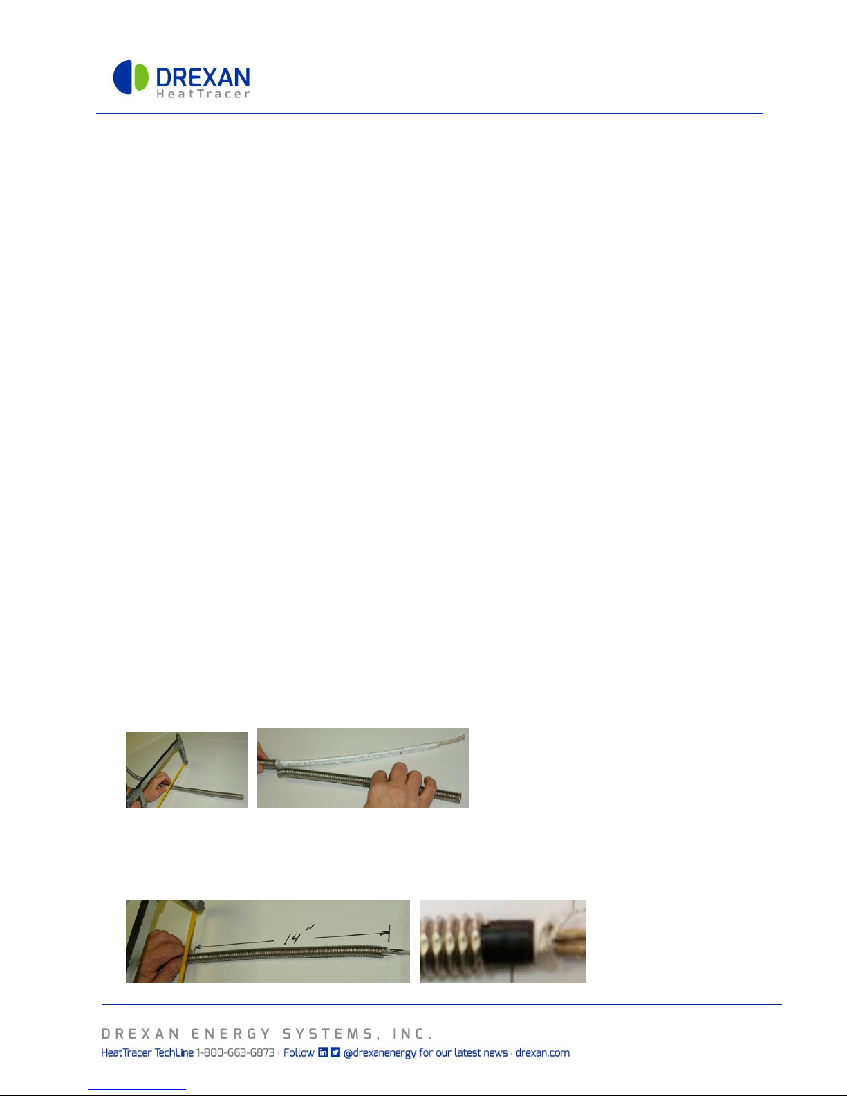
2. Using a hacksaw, cut the desired length of CMH cable allowing an extra three (3) feet (1 m) per end and
appropriate cable length for heat sinks such as valves, flanges and pipe supports.
3. Using a CMH Stripping Tool, strip the sheath back 12” (30.4 cm) from the raw end, remove and discard. This
exposes the core to locate the zone node.
Note: If the cable has two-foot zones you may have to strip back up to 24” (60.8 cm). Refer to chart on page 4.
Zones nodes can be identified by the indent in the core. Strip back the insulation to expose and confirm the
location of the node
Note: If using a hacksaw cut around the sheath being careful not to damage the core.
4. From the node measure 14” (35.5 cm), mark the sheath and strip the sheath to the mark. Discard the sheath.
Wrap a layer of electrical tape around the core, next to the sheath, to prevent the insulation from unwrapping
into the sheath.
 Loading...