

Page 1
2
Bedienungsanleitung
· Working instructions
Mode d‘emploi · Instrucciones de trabajo
Istruzioni d’uso · Gebruiksaanwijzing
deutschdeutschdeutschenglishfrançaisespañolitaliano
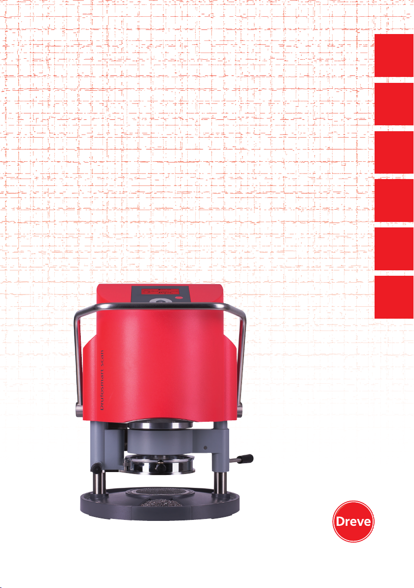
Drufosmart scan
Universelles Druckformgerät 4 bar
Universal pressure thermoforming unit 58 psi
Thermoformeuse universelle sous pression 4 bars
Termoadaptador a presión universal 4 bar
Apparecchio universale per termostampaggio 4 bar
Universeel apparaat voor drukopbouw 4 bar
english deutsch
nederlands
Dreve Dentamid GmbH · Max-Planck-Straße 31 · 59423 Unna/Germany
1
Page 2
deutschenglishfrançaisespañolitaliano
Dreve Design Rev.091018-DU091018-100-D3400ANL
Inhalt
1. Gerätebeschreibung 6
2. Technische Daten 6
3. Konformitätserklärung 7
4. Sicherheitshinweise 8
5. Inbetriebnahme – Lieferumfang 9
6. Funktionselemente 10
7. Display 11
8. Bedienung 12
8.1 Scan Modus 12
8.2 Druckeinstellung 13
8.3 Programmstart 13
8.4 Tiefziehen 14
8.5 Öffnen der Druckkammer 15
9. Abweichungen vom Regelfall 16
9.1 Veränderung von vorgegebenen
Zeiten 16
9.2 Manuell Zeit-Programme
erstellen und abspeichern 17
9.3 Aufrufen individueller
Zeitprogramme 18
9.4 Plastifizieren von Folien mit
unbekannter Aufheizzeit 18
9.5
Programmabbruch / -aufhebung
9.6 Überschreiten der eingegebenen
Heiz- / Kühlzeiten 19
9.7 Eingabe eines falschen Barcodes 19
10. Optionale Zusatzfunktionen 20
10.1 Anfertigung von Gussformteilen 20
11. Pflege und Wartung 20
12.
Auswechseln der Gerätesicherung
13. Allgemeine Hinweise 22
14. Garantie 23
15. Störungshilfen 24
16. Ersatzteillisten 26
17. Explosionszeichnung 129
18. Wirkschaltplan 130
19. Pneumatikplan 131
20. Barcodes 132
18
21
Contents
1. Description of unit 27
2. Technical data 27
3. Declaration of conformity 28
4. Safety advice 29
5. Initiation – scope of delivery 30
6. Functional components 31
7. Display 32
8. Operation 33
8.1 Scan modus 33
8.2 Pressure adjustment 34
8.3 Start of programme 34
8.4 Thermoforming 35
Opening of the pressure chamber
8.5
9. Deviation to the rule 37
9.1 Modification of given times 37
9.2 Creation and storage of manual
time programmes 38
9.3 Calling of individual time
programmes 39
9.4 Plasticizing of blanks with
unknown heating times 39
Abort / termination of programme
9.5
9.6 Exceeding of entered heating/
cooling times 40
Entering a wrong barcode 40
9.7
10. Additional optional functions 41
Fabrication of cast form parts 41
10.1
11. Care and maintenance 41
12. Exchange of fuses 42
13. General advice 43
14. Guarantee 43
15. Trouble shooting 44
16. Spare part list 46
17. Explosion sketch
18. Operating diagram 130
19. Pneumatic plan 131
20. Barcodes 132
36
39
129
nederlands
Page 3
deutschenglishfrancaisespanolitaliano
deutschenglishfrançaisespañolitaliano
Contenu Contenido Indice
1. Description de l’appareil 48
2. Données techniques 48
3. Déclaration de conformité 28
4. Avis de sécurité 49
5. Mise en marche –
Contenu de livraison 50
6. Éléments de fonction 51
7. Display 52
8. Opération 53
8.1 Mode scan 53
8.2 Ajustement de pression 54
Mise en marche du programme
8.3
54
8.4 Thermoformage 55
8.5 Ouverture de la chambre
de pression 56
9. Anomalies 57
9.1 Ajustement manuel des temps
préprogrammés 57
9.2 Création et enregistrement
manuels des programmes
de temps 58
9.3 Se servir des programmes de
temps individuels 59
9.4 Plastification de feuilles avec
un temps de chauffage inconnu 59
9.5 Arrêt / terminaison du
programme 60
9.6 Dépassement des temps de
chauffage / refroidissement
enregistrés 60
9.7 Enregistrement d’un code
barré faux 60
10. Fonctions additionnelles en
option 61
10.1 Production de chapes 61
11. Soin et entretien 61
12. Changement de fusibles 62
13. Avis généraux 63
14. Garantie 63
15. Conseils en cas de panne 64
16. Liste de pièces détachées 66
17. Dessin d’explosion
129
18. Diagramme 130
19. Plan pneumatique 131
20. Codes barrés 132
1. Descripción del equipo 68
2. Características técnicas 68
3. Declaración de conformidad 28
4. Advertencias de seguridad 69
5. Puesta en marcha / volumen
de entrega 70
6. Elementos de función 71
7. Pantalla 72
8. Manejo 73
8.1 Modo escáner 73
8.2 Ajuste de la presión 74
8.3 Inicio del programa 74
8.4 Termoadaptación 75
Apertura de la cámara de presión
8.5
9. Desviaciones con respecto
76
a la norma general 77
9.1 Modificación de los tiempos
programados 77
9.2 Creación y almacenamiento
manual de programas de
temporización 78
9.3 Acceso a programas de
temporización individuales 79
9.4 Plastificación de láminas
con tiempo de calentamiento
desconocido 79
9.5 Interrupción/finalización de
programas 80
9.6 Exceso de los tiempos de
calentamiento/enfriamiento
introducidos 80
9.7 Introducción de un código de
barras incorrecto 80
Funciones adicionales opcionales
10.
10.1 Preparación de piezas de
81
molde de fundición 81
11. Cuidados y mantenimiento 81
12. Sustitución de los fusibles 82
13. Advertencias generales 83
14. Garantía 83
15. Solución de problemas 84
16. Listas de recambios 86
17. Despiece
129
18. Plano de circuitos detallado 130
19. Plano neumático 131
20. Código de barras 132
1. Descrizione dell’apparecchio 88
2. Dati tecnici 88
3. Dichiarazione di conformità 28
4. Avvertenze di sicurezza 89
Messa in funzione – Fornitura
5.
6. Elementi funzionali 91
7. Display 92
8. Comando 93
8.1 Modalità di scan 93
Impostazione della pressione
8.2
8.3 Avvio del programma 94
8.4 Termostampaggio 95
8.5 Apertura della camera di
pressione 96
9. Eccezioni alla regola 97
9.1 Modifica dei tempi previsti 97
9.2 Creazione e salvataggio
manuale di programmi orari 98
9.3 Richiamo di programmi orari
specifici 99
9.4 Plastificazione di fogli con
tempo di riscaldamento
non noto 99
9.5 Interruzione/fine del
programma 100
9.6 Superamento dei tempi
impostati di riscaldamento
e raffreddamento 100
9.7 Immissione di un codice a
barre errato 100
10. Funzioni opzionali 101
10.1 Produzione di cappette per
la tecnica di fusione 101
11. Cura e manutenzione 101
12. Sostituzione dei fusibili
dell’apparecchio 102
13. Avvertenze generali 103
14. Garanzia 103
15. Eliminazione di guasti 104
16. Elenco delle parti di ricambio 106
17. Vista esplosa
18. Schema elettrico 130
19. Schema pneumatico 131
20. Codici a barra 132
Inhoud
1. Beschrijving van het apparaat 108
2. Technische gegevens 108
3. Verklaring van conformiteit 28
4. Veiligheidsinstructies 109
90
94
129
5. Ingebruikname –
leveringsomvang 111
6. Functiespecifieke elementen 112
7. Display 113
8. Bediening 114
8.1 Scanmodus 114
8.2 Afstellen van de druk 115
8.3 Programmastart 115
8.4 Dieptrekken 116
8.5 Openen van de drukkamer 117
9. Afwijkingen van de normale
situatie 118
9.1 Wijzigingen van de ingestelde
tijden 118
9.2 Manueel tijdprogramma’s
aanmaken en opslaan 119
9.3 Opvragen van individuele
tijdprogramma’s 120
9.4 Plastificeren van folie met
onbekende opwarmtijd 120
9.5 Afbreken/beëindigen van het
programma 120
9.6
Overschrijden van de ingestelde
verwarmings- / afkoeltijden 121
9.7
Invoeren van een foute barcode
10. Optionele extra functies 122
10.1
Vervaardigen van gietvormdelen
11. Reiniging en onderhoud 123
12. Vervangen van de zekeringen
bij het apparaat 123
13. Algemene opmerkingen 124
14. Garantie 125
15. Hulp bij het verhelpen van
storingen 126
16. Lijsten voor reserveonderdelen 128
17. Afbeelding in vergroting 129
18. Schakelplan 130
19. Pneumatisch plan 131
20. Barcodes 132
121
122
nederlands
Page 4
Drufosmart scan
deutsch
1. Gerätebeschreibung
Der Drufosmart scan ist ein universell
einsetzbares Druck-Tiefziehgerät für den
täglichen Betrieb im Dentallabor. Eine,
in das Gerät integrierte Scaneinrichtung
ermöglicht die direkte Übernahme von
Produktnamen, Plattenstärke sowie den
individuellen Heiz- und Abkühlzeiten
mittels eines auf jeder Packungseinheit
angebrachten Barcodes.
Ein fest eingestellter Anformdruck von
4 bar in Verbindung mit der vertikal
anformenden Folie garantiert äußerst
präzise Ergebnisse.
2. Technische Daten
Abmessungen (H x B x T): 420 x 320 x 290 mm
Gewicht: 15 kg
Netzspannung: 100–240 V / 50–60 Hz
Max. Leistungsaufnahme: 115 V–270 W, 230 V–315 W
Gerätesicherung: T 3,15 A
Betriebsdruck: 4 bar
Min. Betriebsdruck: 2 bar
Max. Leitungsdruck: 10 bar
6
3. Konformitätserklärung
gemäß Maschinenrichtlinie (2006 / 42 / EG), Anhang II A.
Hiermit erklären wir, dass das nachstehend beschriebene Gerät in seiner Konzipierung und Bauart
sowie in der von uns in Verkehr gebrachten Ausführung den grundlegenden Sicherheits- und
Gesundheitsanforderungen der EG-Richtlinien entspricht. Bei einer nicht mit uns abgestimmten
Änderung der Maschine verliert diese Erklärung ihre Gültigkeit.
Bezeichnung der Maschine: Drufosmat scan
Maschinentyp: Druck-Tiefziehgerät
Zutreffende EG-Richtlinien:
2014 / 35 / EU Niederspannungs-Richtlinie
2014 / 30 / EU EMV-Richtlinie
Die Schutzziele der EU-Richtlinie 2006 / 42 / EG werden eingehalten.
Folgende harmonisierte Normen wurden angewandt:
2006 / 42 / EG Maschinenrichtlinie
EN ISO 12100:2010 +
Berichtigung 1;
zu 12100:2011-03
EN ISO 13732-1:2008
DIN EN 60204-1:2006 /
A1:2009 + Berichtigung 1;
zu DIN EN 60204-1
2
014 / 35 / EU Niederspannungs-Richtlinie
EN 61010-1:2010
2014 / 30 / EU EMV-Richtlinie
EN 61000-3-2:2014
EN 61000-3-3:2013
EN 61326-1:2013
Sicherheit von Maschinen – Allgemeine Gestaltungsleitsätze; Risikobeurteilung und Risikominderung (ISO 12100:2010); Deutsche Fassung
EN ISO 12100:2010 + Berichtigung 1; zu 12100:2011-03
Ergonomie der thermischen Umgebung – Bewertungsverfahren für
menschliche Reaktionen bei Kontakt mit Oberflächen – Teil 1: Heiße
Oberflächen (ISO 13732-1:2006); Deutsche Fassung EN ISO 137321:2008-12
Sicherheit von Maschinen; Elektrische Ausrüstung von Maschinen; Teil 1:
Allgemeine Anforderungen (IEC 60204-1:2005 / A1:2008); Deutsche Fassung EN 60204-1:2006 / A1:2009; + Berichtigung 1 zu DIN EN 60204-1;
Deutsche Fassung EN 60204-1:2006
Sicherheitsbestimmungen für elektrische Mess-; Steuer-; Regel und Laborgeräte; Teil 1: Allgemeine Anforderungen (IEC 61010-1:2010 + Cor.:
2011); Deutsche Fassung EN 61010-1:2010
Elektromagnetische Verträglichkeit (EMV) – Teil 3-2: Grenzwerte –
Grenzwerte für Oberschwingungsströme (Geräte-Eingangsstrom <= 16 A
je Leiter) (IEC 61000-3-2:2014); Deutsche Fassung EN 61000-3-2:2014.
Elektromagnetische Verträglichkeit (EMV) – Teil 3-3: Grenzwerte – Begrenzung
von Spannungsänderungen, Spannungsschwankungen und Flicker in öffentlichen
Niederspannung-Versorgungsnetzen für Geräte mit einem Bemessungsstrom <=
16 A je Leiter, die keiner Sonderanschlussbedingung unterliegen (IEC 61000-33:2013); Deutsche Fassung EN 61000-3-3:2013
Elektrische Mess-, Steuer-, Regel- und Laborgeräte – EMV-Anforderungen;
Teil1: Allgemeine Anforderungen (IEC 61326-1:2012); Deutsche Fassung
EN 61326-1:2013 Emission nach Wohnbereich, Gewerbebereich und
Kleinbetriebe; Störfestigkeit nach Industriebereich.
Dreve Dentamid GmbH · Max-Planck-Straße 31 · 59423 Unna / Germany
Tel.: +49 2303 8807-40 · [email protected] · www.dentamid.dreve.de
D3400 / D3400A / D34001 / D34001A
englishfrançaisespañolitaliano
nederlands
7
Page 5
Drufosmart scan
4. Sicherheitshinweise
deutsch
Achtung! Lesen Sie diese Hinweise vor dem Anschließen und der Inbetriebnahme
des Gerätes sorgfältig durch. Die Betriebssicherheit und die Funktion des Gerätes
können nur dann gewährleistet werden, wenn sowohl die allgemeinen Sicherheits- und
Unfallverhütungsvorschriften des Gesetzgebers als auch die Sicherheitshinweise in der
Bedienungsanleitung beachtet werden.
1. Das Gerät darf nur entsprechend der
vorliegenden Bedienungsanleitung verwendet werden. Wir übernehmen keine
Haftung für Schäden, die durch unsachgemäßen Gebrauch, bzw. fehlerhafte
Bedienung entstehen.
2. Das Gerät muss auf einem ebenen
Untergrund stehen und für das etwa
20 kg schwere Betriebsgewicht ausreichend stabil und belastbar sein.
3. Um Eindringen von Wasser in das
Gerät (z. B. Spritzwasser) zu vermeiden,
sollte das Gerät in trockener Umgebung
aufgestellt werden.
4. Bewahren Sie keine leichtentzündlichen Stoffe in unmittelbarer Umgebung
des Gerätes auf.
5. Die angegebene Spannung auf dem
Typenschild muss mit der Spannung der
Stromquelle übereinstimmen.
6. Das Gerät nur an einer Steckdose mit
Schutzleiter betreiben. Den Netzstecker
niemals mit feuchten Händenanfassen.
7. Zugelassene Bediener: Der Betreiber
der Maschine muss dem Bediener die
Betriebsanleitung zugänglich machen
und sich vergewissern, dass er sie
gelesen und verstanden hat. Erst dann
darf der Bediener das Gerät in Betrieb
nehmen.
8. Das Gerät ist vor jedem Betrieb
auf ordnungsgemäßen Zustand und
Betriebsicherheit zu überprüfen. Falls
der Zustand nicht einwandfrei ist, darf
das Gerät nicht benutzt werden und
muss entsprechend gekennzeichnet
werden.
9. Der Druck der Druckluftleitung darf
10 bar nicht überschreiten.
10. Keine Gegenstände in das Gerät
einführen.
11. Die Bedienungselemente des Gerätes nicht arretieren.
12. Den herabfahrenden Kolben nicht
blockieren.
13. Nicht unter den herabfahrenden
Kolben greifen.
14. Das schwenkbare Gehäuse des
Heizstrahlers erreicht im Betrieb hohe
Temperaturen und darf deswegen auch
kurzfristig nicht berührt werden.
15. Das Gerät ist bei längerfristiger
Nichtbenutzung vom Netz zu trennen.
16. Schilder und Aufkleber müssen stets
in gut lesbarem Zustand gehalten werden und dürfen nicht entfernt werden.
17. Vor der Reinigung und der Wartung
des Gerätes oder dem Auswechseln von
Teilen ist unbedingt der Netzstecker zu
ziehen.
18.
Das Öffnen des Gerätes und
Instandsetzungen dürfen nur von zugelassenen Fachkräften durchgeführt werden.
19. Es dürfen nur Zubehör und Ersatzteile verwendet werden, die vom Her-
5. Inbetriebnahme
Vor der Inbetriebnahme ist sicher zu
stellen, dass die auf dem Typenschild
angegebene Netzspannung mit der
Spannung der Stromquelle überein
stimmt.
Anschließen des Gerätes an einen Druckluft-Kompressor.
Druckschlauch in den Druckluftsteckanschluss (9) durch Überwindung eines leichten Widerstandes einstecken. Der Schlauch
ist dann automatisch fixiert. Zum Lösen
des Druckschlauches den blauen Ring der
Kupplung nach oben drücken und den
Schlauch nach unten entfernen.
Der Leitungsdruck darf 10 bar nicht
überschreiten.
Dafür den mitgelieferten
steller freigegeben sind. Für Schäden,
die durch den Einsatz fremder Teile entstehen, übernehmen wir keine Haftung.
20. Eigenmächtige Umbauten und Veränderungen sind aus Sicherheitsgründen unzulässig.
21.
Die vorgeschriebenen Betriebsund Wartungsbedingungen dieser
Gebrauchsanleitung sind zwingend einzuhalten. Beim Arbeiten mit dem Drufosmart scan sind die allgemeinen Unfallverhütungsvorschriften zu beachten.
Netzkabel in die Gerätesteckdose (33)
stecken und Netzverbindung mit dem
Euro/USAStecker herstellen.
-
Wichtig: Vor der ersten Inbetriebnahme
unbedingt die Gebrauchsinformation
gründlich lesen. Bei Verständnisunsicherheiten ggf. Rücksprache mit dem
zuständigen Depot oder direkt mit der
Firma Dreve Dentamid GmbH nehmen.
Lieferumfang
1 Drufosmart scan
1 Granulatschublade
1 Einsatzschale und Noppenplatte
1 Spannring mit Ablassventil
1 Basissortiment Folien
1 Netzkabel
1 Druckluftschlauch inkl. Schlauch-
klemmen und Schnellkupplung
1 Gebrauchsanleitung 6-sprachig
englishfrançaisespañolitaliano
nederlands
8
9
Page 6
Drufosmart scan
deutsch
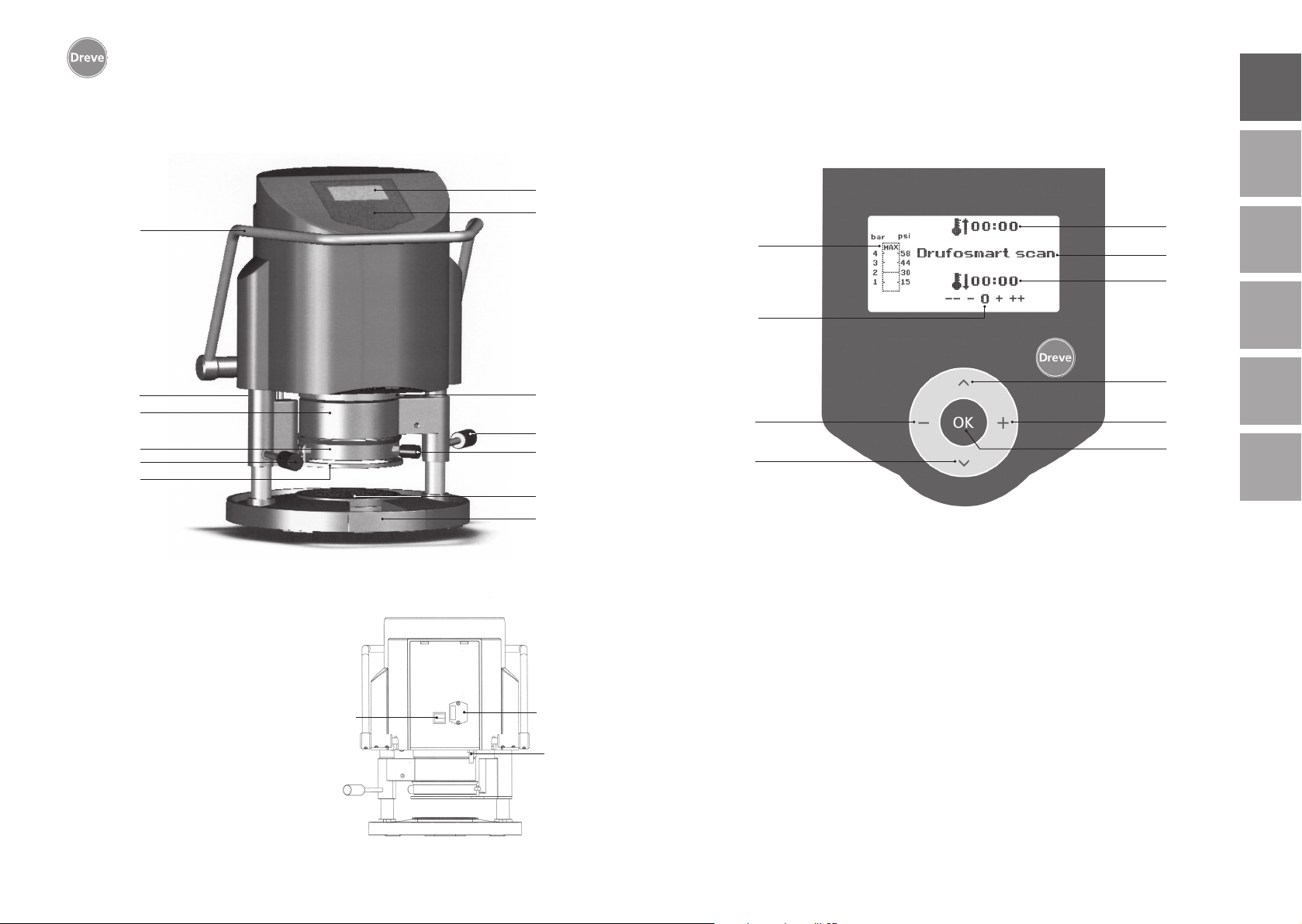
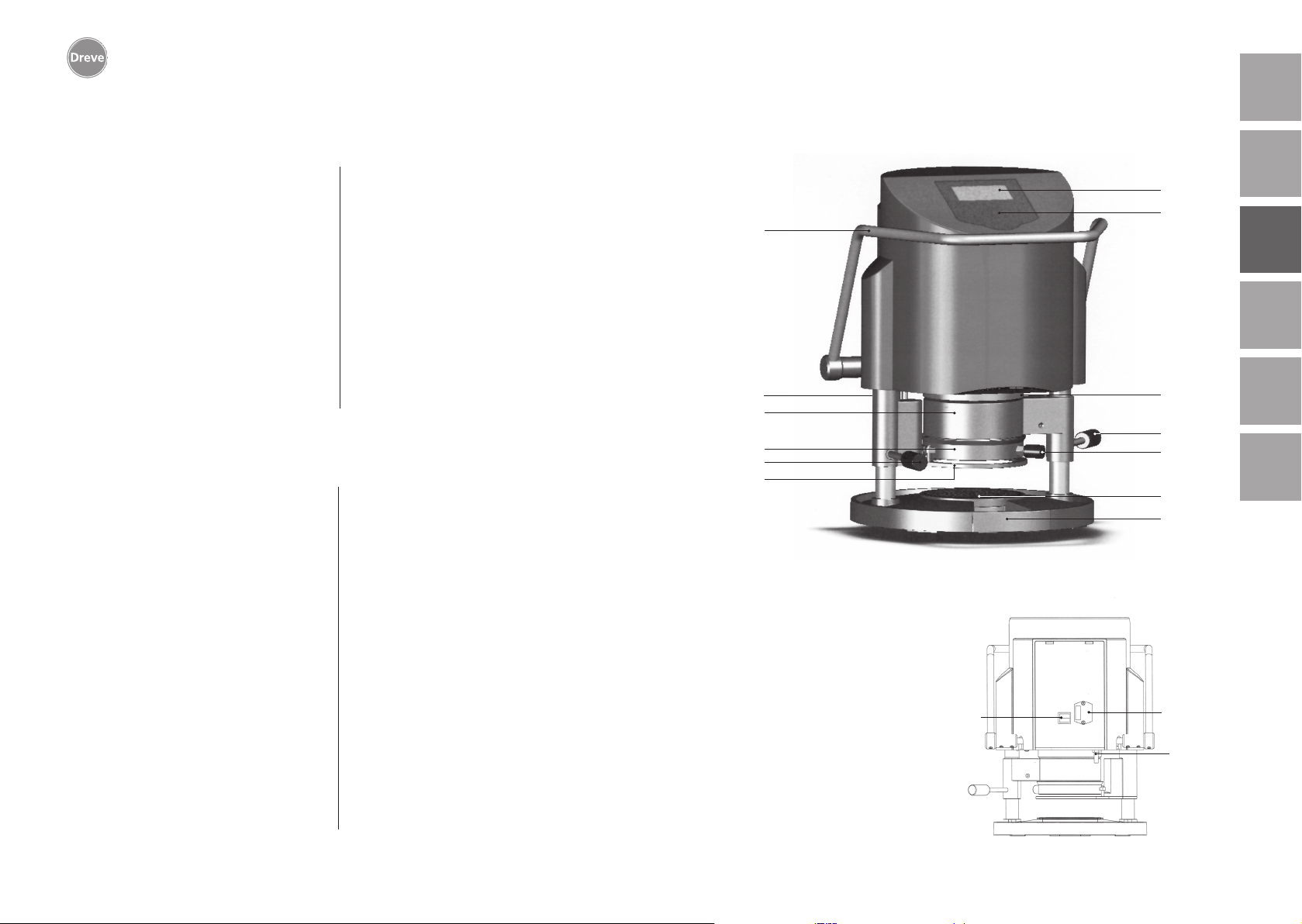
6. Funktionselemente
34
9
4
13
10
11
Nr. Bezeichnung
1 Scanner
2 Display
3 Tastatur
4 Heizungselement
5 Handgriff Heizung
6 Noppenplatte und Einsatzschale
7 Granulatschublade
9 Druckluftanschluss
10 Handgriff Plattenteller
11 Plattenteller
12 Entlüftungsventil
13 Spannring
33 Netzanschluss/Sicherungshalter
34 Aktivierungshebel
43 Hauptschalter
43
2
3
1
5
12
6
7
33
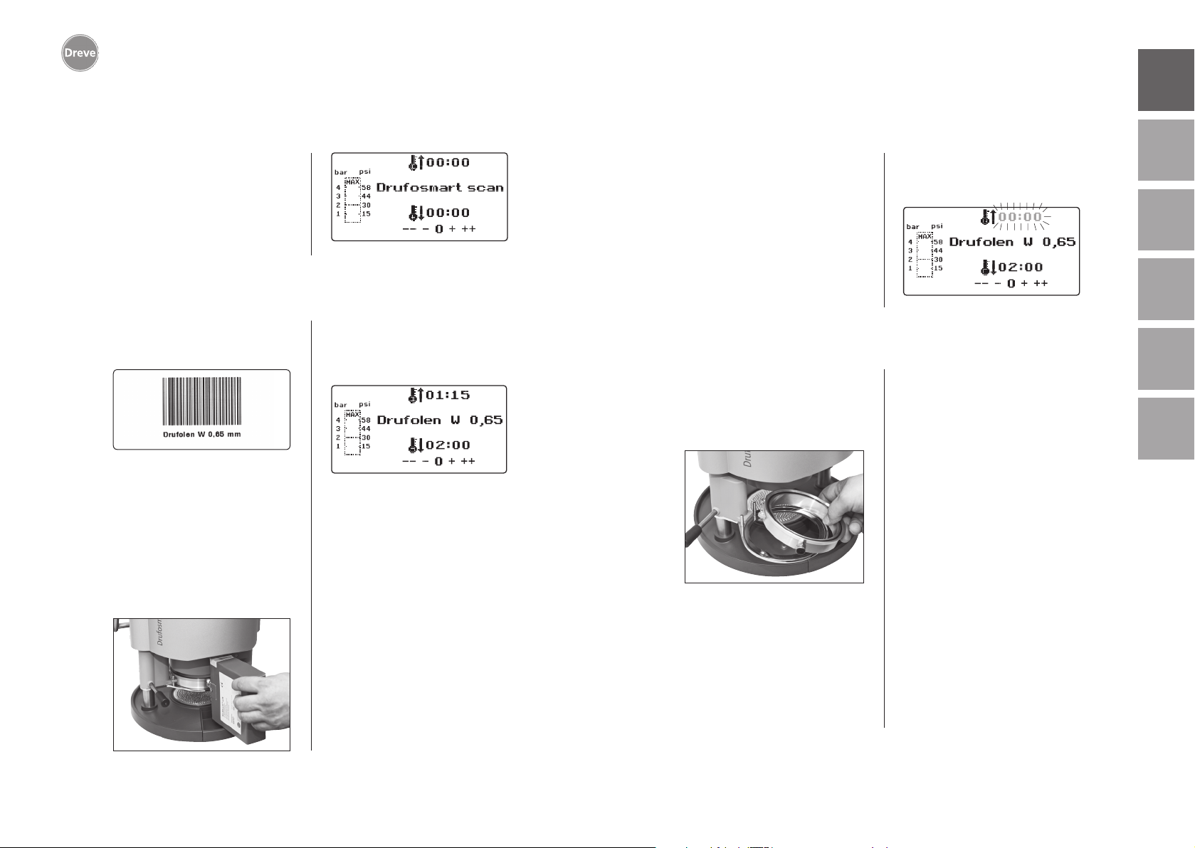
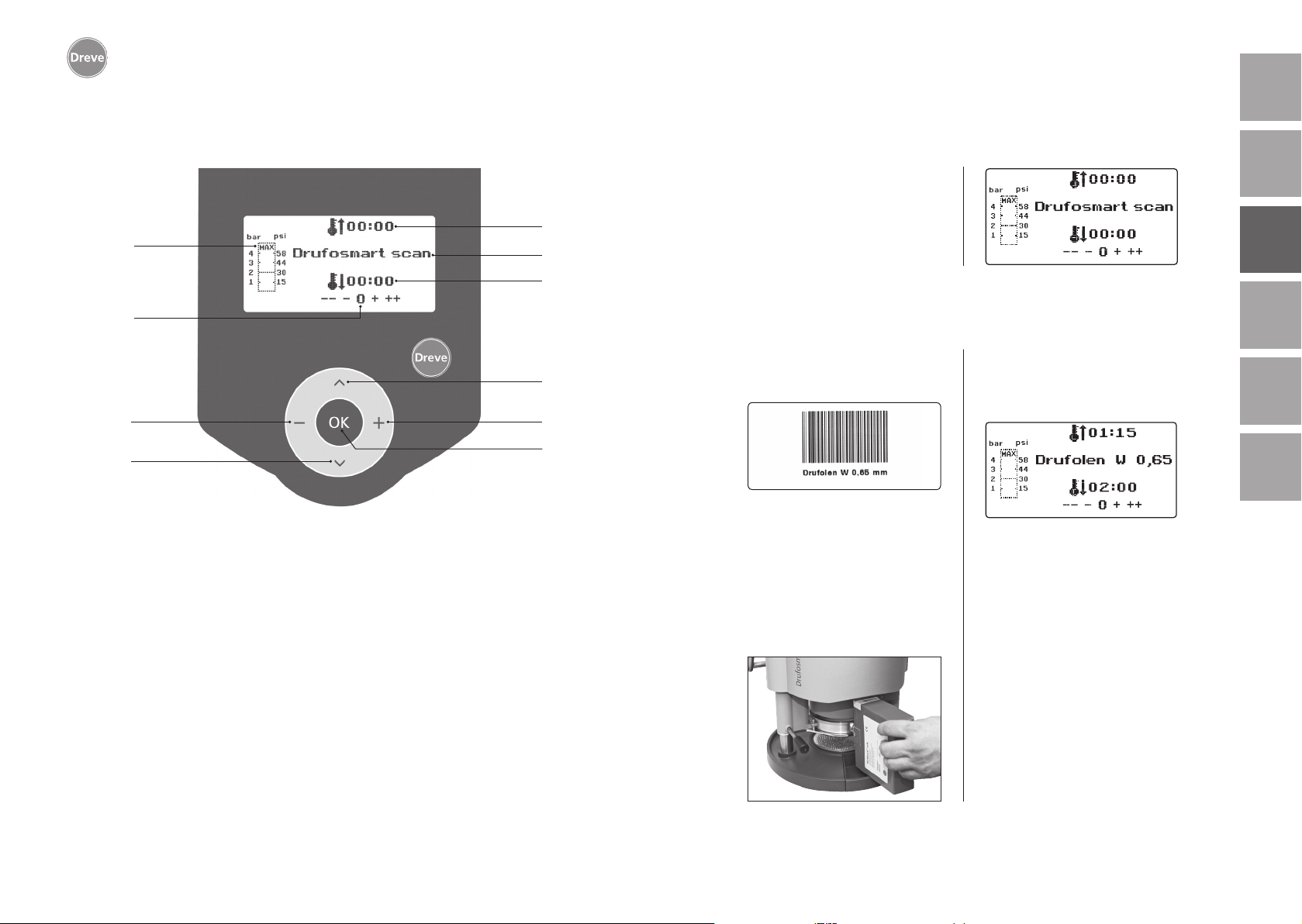
7. Display
englishfrançaisespañolitaliano
a
g
h
i
j
Nr. Bezeichnung
a Anzeige der Heizzeit
b Anzeige Produktname und Materialstärke
c Anzeige der Kühlzeit
d Menüpunkte wechseln (rückwärts)
e Änderung von Zeitangaben (aufwärts)
f Bestätigungstaste/Starttaste Heizung
g Anzeige des Kolbeninnendruckes
h Kontrollanzeige für individuelle Zeitänderungen
i Änderung von Zeitangaben (abwärts)
9
j Menüpunkte wechseln (vorwärts)
b
c
d
e
f
nederlands
10
11
Page 7
Drufosmart scan
deutsch
8. Bedienung
Hauptschalter (43) auf der Rückseite
des Gerätes einschalten, Scanner (1)
und Display (2) an der Frontseite werden aktiviert. Ein Signalton zeigt die
Einsatzbereitschaft des Gerätes an,
im Display erscheint der Gerätename
Drufosmart scan.
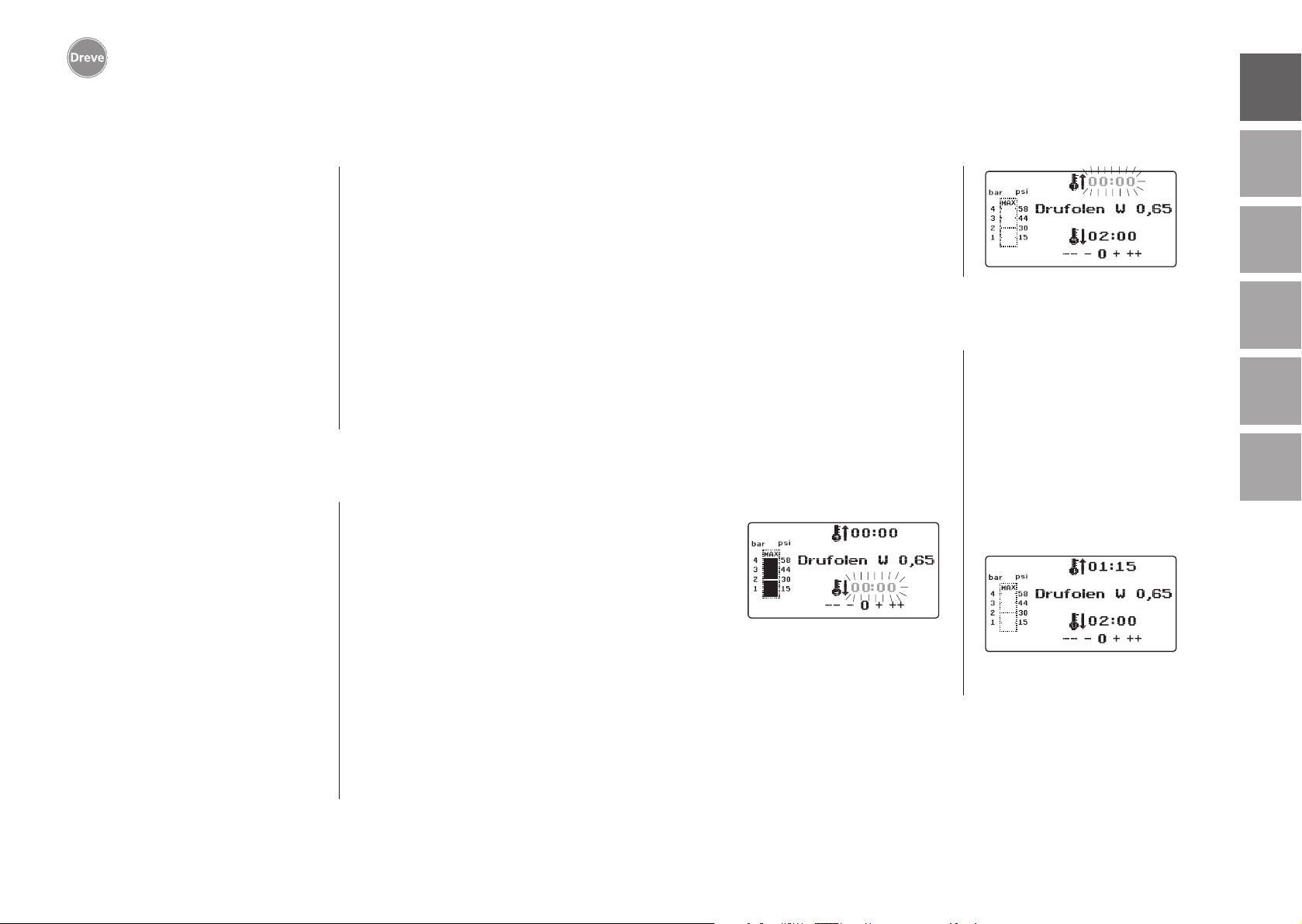
8.1 Scan Modus
Auf jeder Außenverpackung mit Dreve
Tiefziehfolien befindet sich ein Barcodeetikett.
Dieser Barcode enthält in verschlüsselter Form Produktnamen, Materialstärke
sowie die individuellen Heiz- und Abkühlzeiten.
Um die Materialdaten in den Drufosmart
scan einzulesen muss der Barcode möglichst zentral und gerade unter das Scannerfeld (1) gehalten werden.
Als Bestätigung für die Datenaufnahme
ertönt ein Bestätigungssignal und im
Display werden alle notwendigen Daten
aufgezeigt.
Info
Das vom Scanner ausgehende
Licht ist unschädlich und hat auch
bei direktem Blickkontakt keine
negativen Auswirkungen!
Der Scanner schaltet sich nach
15 Min. ohne Gebrauch automatisch ab. Die Reaktivierung erfolgt
durch das Drücken der OK-Taste.
Während eines aktiven Tiefzieh
prozess ist der Scanner deaktiviert. Nach Beendigung des Vorgangs schaltet er sich automatisch
wieder ein.
8.2 Druckeinstellung
Der Eingangsdruck vom Kompressor
darf 10 bar nicht überschreiten! Ggf.
ein Reduzierventil in die Zuleitung einbauen bzw. Gesamtdruck des Kompressors absenken.
Der Arbeitsdruck des Drufosmart scan
beträgt 4 bar (58 psi) Dieser wird digital
gesteuert und permanent kontrolliert.
Der tatsächliche Druck in der Druckkam-
mer während des Tiefziehprozeß kann
im Balkendiagramm (g) des Displays
abgelesen werden.
englishfrançaisespañolitaliano
8.3 Programmstart
Um das gewählte Programm zu starten,
legen Sie eine, dem Barcode bzw. der
Programmierung entsprechende Folie
auf den Plattenteller (11) und fixieren
diese mit Hilfe des Spannringes (13).
Das Modell wird wahlweise auf die
Noppenplatte (6) oder durch Entnahme
der Noppenplatte mittels Granulat in
-
der Einsatzschale (6a) fixiert.
Info
Für eine optimale Adaption der
Folie an das Modell fixieren Sie
die Modelle immer mit den Front-
zähnen zur Folienmitte. Bei der
Verwendung von harten Tiefziehfolien empfiehlt sich die Einbettung in Granulat. Modelle, die auf
der Noppenplatte fixiert werden,
sollten ein max. Höhe von 23 mm
nicht überschreiten.
Schwenken Sie den Plattenteller am
Griffstück (10) bis zur mechanischen
Arretierung ins Zentrum unter das
Gerät. Schwenken Sie den Heizstrahler (4) am Griffstück (5) ebenfalls bis
zum Anschlag ins Zentrum des Gerätes.
Schließen Sie das Entlüftungsventil des
Spannringes (12).
Drücken Sie die OK-Taste (f). Als Bestätigung für die Aktivierung der Heizung
ertönt ein Signalton, die Scaneinheit
erlischt und im Display läuft die voreingestellte Heizzeit ab.
nederlands
12
13
Page 8
Drufosmart scan
deutsch
Info
Aus Sicherheitsgründen ist der
Quarzstrahler mit einem Endschalter ausgestattet und funktioniert
ausschließlich im eingeschwenkten Zustand nach Start eines Programms.
Wird der Quarzstrahler während
der aktiven Heizphase ausgeschwenkt, wird der Heizprozess
automatisch unterbrochen. Die
Anzeige im Display (a) stoppt und
zeigt den Restwert an. Durch Wiedereinschwenken des Quarzstrahlers wird das Programm reaktiviert.
8.4 Tiefziehen
Nach Ablauf der Aufheizzeit ertönt ein
Signalton, die Heizzeit im Display steht
auf 00:00. Die Heizung schaltet automatisch ab. Drehen Sie die Heizung (4)
mit der rechten Hand an der Knopfstange (5) komplett aus dem Gerätezentrum heraus.
Mit der linken Hand wird anschließend
der Aktivierungshebel (34) bis zum
Anschlag nach unten gedrückt. Durch
nochmaliges Anziehen der HeizungsKnopfstange (5) bis zum Anschlag
schließt die Druckkammer vollständig
und baut automatisch den Innendruck
des Kolbens auf. Zur Bestätigung der
Druckbeaufschlagung ertönt ein Signalton.
Achtung! Das schwenkbare
Gehäuse des Heizstrahlers
erreicht hohe Temperaturen und
darf deswegen auch kurzzeitig
nicht berührt werden.
Nach Ablauf der eingestellten Zeit
blinkt die Anzeige (a) im Display
und zählt die Dauer nach Ablauf
der Heizzeit. Dieser Prozess kann
durch das nachfolgende Tiefziehen
unterbrochen werden.
Info
Aus Sicherheitsgründen kann der
Druck in der Druckkammer erst
aktiviert werden, wenn diese
bereits vollständig manuell abgesenkt wurde. Um das Bedienpersonal verlässlich vor Quetschungen
der Finger zu schützen kann der
Druckaufbau nur stattfinden wenn
das Gerät gleichzeitig mit beiden
Händen bedient wird (Zweihandsicherung). Immer darauf achten, dass sich beim Schließen des
Kolbens keine Gegenstände im
Kontaktbereich Kolben und Einsatzschale befinden!
Der Druck wird automatisch auf die
4 bar aufgebaut. Der Innendruck der
Kammer wird durch die Elektronik permanent überprüft und ggf. nachreguliert. Im Display wird die vorgegebene
Abkühlzeit (c) angezeigt und läuft rückwärts zählend gegen 00:00.
8.5 Öffnen der Druckkammer
Um eine vollständige Rückkühlung der
Tiefziehfolie zu erreichen sollte nach 2/3
der eingegebenen Kühlzeit das Ventil
am Spannring (12) leicht geöffnet werden. Hierdurch wird die aufgewärmte
Luft der Druckkammer abgelassen und
aufgrund der Druckregulierung der Elektronik durch kalte Luft ersetzt. Nach
Ablauf der Kühlzeit ertönt ein Signalton (Anzeige im Display (c) blinkt).
Die Knopfstange der Heizung (5) noch
einmal bis zum Anschlag ziehen und
in dieser Position halten bis der Druck
abgebaut wird (ca. 2–3 Sek.).
Anschließend wird die Druckkammer
durch das Zurückführen des Aktivierungshebels (34) wieder in die Ausgangsposition gebracht. Plattenteller
(11) am Handgriff (10) herausschwenken, Spannring und Tiefziehergebnis
entnehmen.
Im Display (2) erscheint das zuletzt
genutzte Programm, die Scaneinheit
(1) ist für einen neuen Tiefziehprozess
wieder betriebsbereit.
englishfrançaisespañolitaliano
nederlands
14
15
Page 9
Drufosmart scan
deutsch
9. Abweichungen vom Regelfall
9.1 Änderungen von vorgegebenen Zeiten
Eingescannte Zeiten können bei Bedarf
individuell verlängert oder verkürzt werden.
Info
Die Leistung der Heizung kann
nach 1000 Betriebsstunden leicht
nachlassen. Durch eine Verlängerung der Heizzeiten von 5–10 Sek.
können dann wieder optimale Tief
ziehergebnisse erreicht werden.
Die durch den Barcode vorgegebenen Zeiten sind Mittelwerte und
für den allgemeinen Gebrauch ausgelegt. Bei besonders stark unter
sich gehenden Gebieten oder sehr
hohen Modellen kann eine Verlängerung der Heizzeit die Ergebnisse
optimieren.
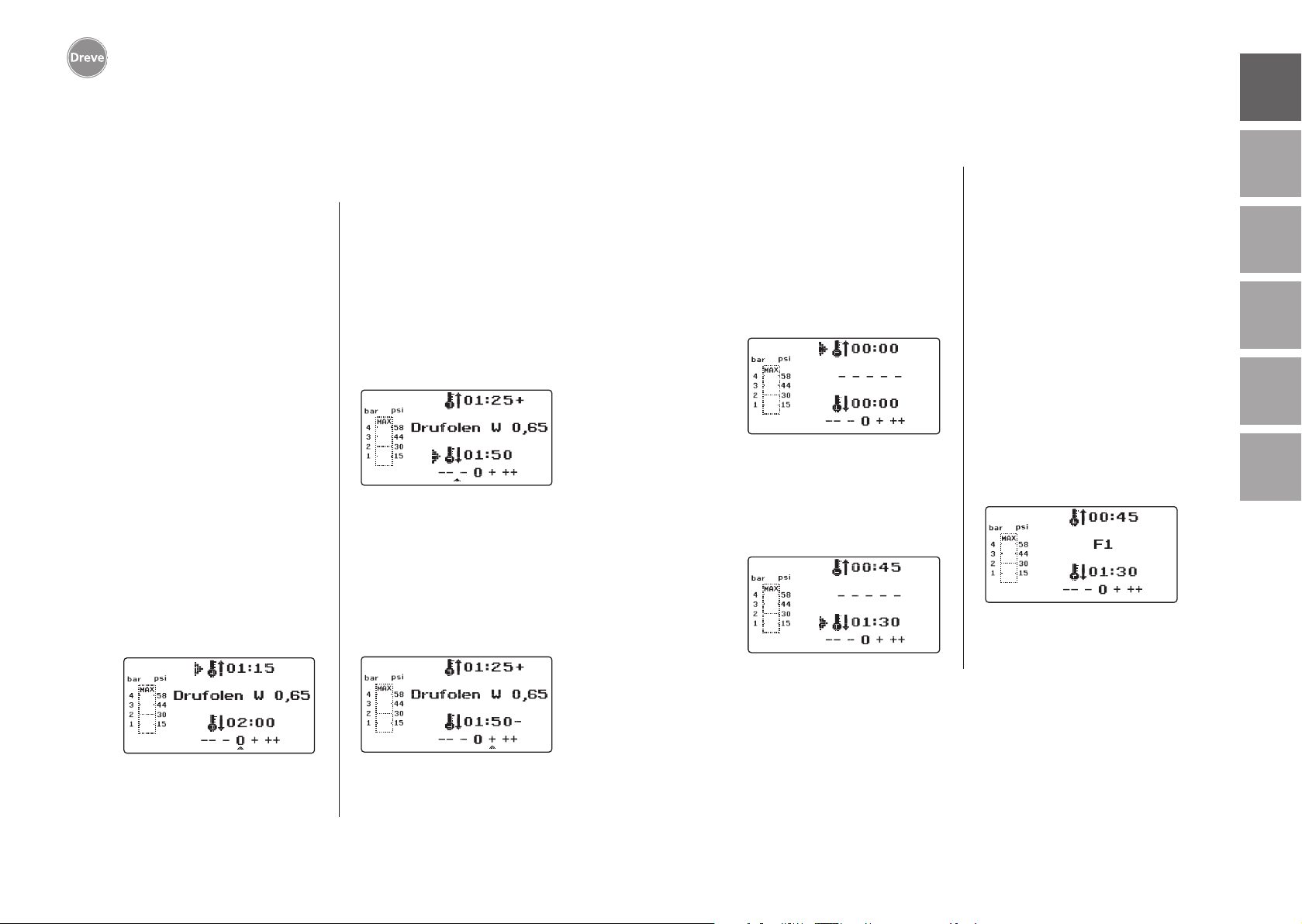
Nach dem Einscannen der vorgegebenen Materialparameter (s. Absatz 8.1)
kann durch Drücken der Menütaste (j)
die Heizzeit (1 x) oder die Kühlzeit (2 x)
angewählt werden. Im Display erscheint
vor der gewählten Zeitvorgabe ein Pfeil.
-
Die Aufheizzeit kann in 5-SekundenSchritten sowohl positiv wie negativ verändert werden. Hierfür Menütasten (e/i)
entsprechend der Tastenbezeichnung
drücken. Die maximale Abweichung zur
Scanzeit beträgt 35 Sekunden.
Die Abkühlphase kann mit den gleichen
Arbeitsschritten in 10-Sekunden-Schritten um maximal 70 Sekunden geändert
werden.
Zur Kennzeichnung der geänderten
Parameter erscheint im Display hinter
der Anzeige ein + bzw. ein – Zeichen.
Die Stärke der Abweichung wird über
eine Skala am unteren Displayrand
angezeigt.
Veränderte Werte müssen durch Drücken
der OK-Taste (f) bestätigt werden.
9.2 Manuell Zeit-Programme erstellen und abspeichern
Für Tiefziehfolien, die nicht mit einem
entsprechenden Barcode ausgestattet
sind, können bis zu drei individuelle
Zeitprogramme eingegeben und abgespeichert werden.
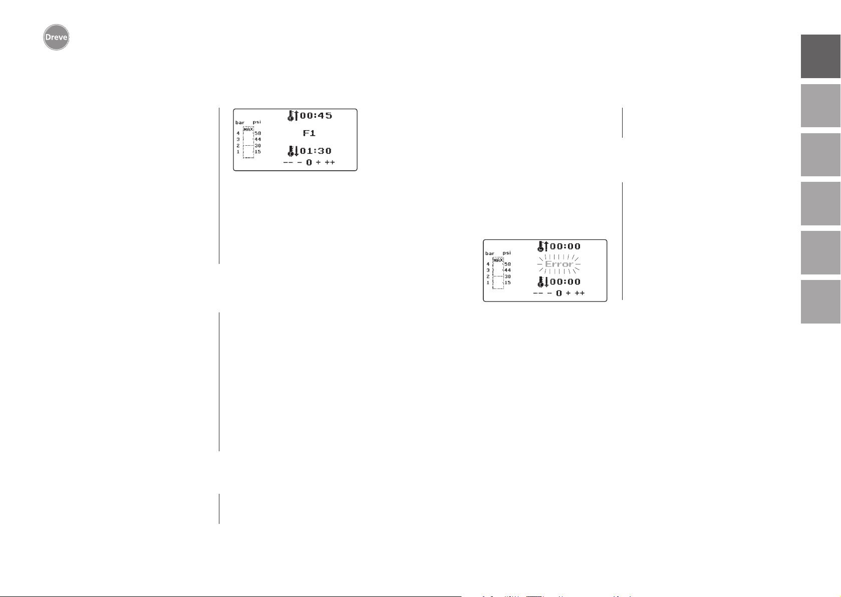
Gerät einschalten. Im Display erscheint
das Ausgangsdisplay. Durch einmaliges
Drücken der Menütaste (j) erscheint im
Display an Position b – – – – –.
Wie unter Punkt 9.1 beschrieben Menütaste (j) drücken und den gewünschten
Wert über die Menütasten +/- (e/i) für
die Heizzeit eingeben. Anschließend
erneut Menütaste (j) drücken und die
entsprechende Abkühlphase eingeben.
Für den einmaligen Gebrauch beide eingegebenen Werte mit der OK-Taste (f)
bestätigen. Weiter wie ab Punkt 8.2
beschrieben.
Soll das erstellte Zeitprogramm für den
mehrfachen Gebrauch abgespeichert
werden stehen Ihnen 3 Speicherplätze
(F1–F3) zur Verfügung.
Das erstellte Zeitprogramm (s. o.) nicht
mit OK-Taste bestätigen, sondern
erneut Menütaste (j) drücken. In der
Displayposition b erscheint F1, die eingegeben Zeiten werden übernommen.
Die Speicherplätze F2 und F3 werden
durch zwei- bzw. dreimaliges Drücken
der Menütaste (j) aufgerufen. Zeiten auf
dem gewünschten Speicherplatz durch
Drücken der OK-Taste (f) abspeichern.
Weiter wie ab Punkt 8.2 beschrieben.
englishfrançaisespañolitaliano
nederlands
16
Alle weiteren Arbeitsschritte wie ab 8.2
beschrieben.
17
Page 10
Drufosmart scan
deutsch
9.3 Aufrufen individueller Zeitprogramme
Gerät einschalten. Im Display erscheint
das Ausgangsdisplay. Durch mehrfaches
Drücken der Menütaste (j) wählen Sie
hintereinander:
a) den Eingabemodus
b) F1
c) F2
d) F3
Mit den Menütasten (d/j) können Sie
beliebig zwischen den o. g. Programmpunkten navigieren. Den gewählten
Programmpunkt mit der OK-Taste (f)
bestätigen.
9.4
Plastifizieren von Folien mit unbekannter Aufheizzeit
Erstellen Sie ein individuelles Zeitprogramm mit hohen Heiz- und Kühlzeiten (s. Punkt 9.2). Programm starten
(s. Punkt 8.2). Den Plastifizierungsgrad der Folie können Sie mittels eines
stumpfen Metallinstruments (z. B.
Wachsmesser) abtasten.
Info
Die vollständige Verformbarkeit
der Folie kann nur am Rand ertas
tet werden, da hier die Wärme
durch Metallkontakte abfließt
-
Weiter wie ab Punkt 8.2 beschrieben.
und die erforderliche Flexibilität
zuletzt erreicht wird!
Nach Erreichen der notwendigen Flexibilität Tiefziehprozess auslösen (s. Punkt
8.4). Die verbleibende Heizzeit wird in
der Displayanzeige (a) gelöscht, die eingestellte Abkühlphase wird rückwärts
zählend angezeigt (c).
Die Kühlphase kann jederzeit durch
Ziehen der Heizungs-Knopfstange (5)
abgebrochen werden.
9.6 Überschreiten der eingegebenen Heiz- / Kühlzeiten
Nach Ablauf der regulär eingestellten
Zeiten (Displayposition a / c) ertönt ein
Signalton. Als Kontrollmechanismus
wird die überschrittene Zeit im Display
blinkend angezeigt.
9.7 Eingabe eines falschen Barcodes
Wird ein Barcode eingescannt, der nicht
der Programmierung des Drufosmart
scan entspricht, ertönen vier kurze
Warnsignale und im Display erscheint
an Position b das Wort ERROR (Fehler).
Durch erneutes Einscannen des richtigen Barcodes kann wie ab Punkt 8.0
beschrieben weiter verfahren werden.
englishfrançaisespañolitaliano
nederlands
18
9.5 Programmabbruch/-aufhebung
Während eines ablaufenden Zeitprogramms ist die Tastatur deaktiviert. Der
Abbruch/die Aufhebung aller Aktionen
kann durch das Heranziehen der Heizungsknopfstange (5) bis zum Anschlag
(ca. 3 Sek.) ausgeführt werden.
19
Page 11
Drufosmart scan
deutsch
10 Optionale Zusatzfunktionen
10.1 Anfertigung von Gussformteilen
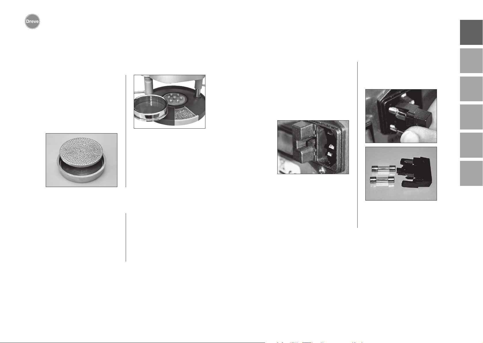
Mit dem K-7 Einsatz können bis zu
7 Kunststoffkappen für die Kronen- und
Brückentechnik gleichzeitig tiefgezogen
werden. Einzelstümpfe mittels eines flexiblen Ausblockmaterials (z. B. Fillin) in
den dafür vorgesehenen Aussparungen
des K-7 Einsatzes fixieren. Noppenplatte
aus der Einsatzschale entnehmen und
durch den K-7 Einsatz ersetzen.
Alle weiteren Arbeitsschritte wie ab
Punkt 7.1 beschrieben.
11. Pflege und Wartung
Vor Pflege- und Wartungsarbeiten
grundsätzlich den Netzstecker vom
Stromnetz trennen.
gungsmittel. Wasser und Reinigungsmittel dürfen nicht in das Gerät gelangen.
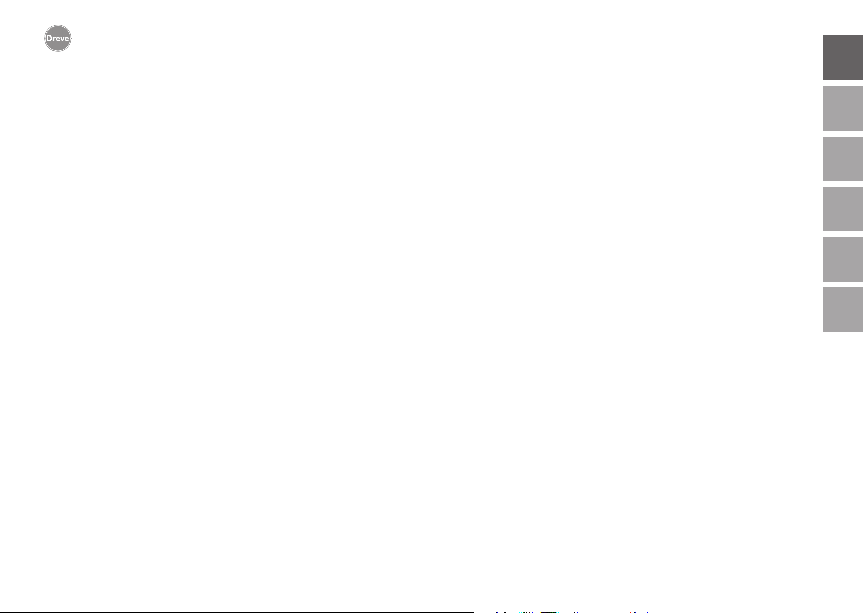
12. Auswechseln der Gerätesicherung
Stromkabel vom Netz trennen. Der
Sicherungshalter befindet sich auf der
Geräterückseite integriert in den Netzanschluss.
Für die Kontrolle oder Wechsel der
Sicherungen Druckraster des Halters
eindrücken, gedrückt halten und den
Halter aus dem Gerät herausziehen.
Die defekte Sicherung mit leichtem Zug
aus der Klemmhalterung herausziehen
und durch eine neue, gleichwertige
Sicherung ersetzen.
Wichtig: Nur die auf der Rückseite
angegebene Sicherungsstärke verwenden.
Nach dem Wechsel den Sicherungshalter mit leichtem Druck wieder ins
Gehäuse einsetzen bis die Fixierung
merklich einrastet.
englishfrançaisespañolitaliano
nederlands
20
Die Reinigung erfolgt idealerweise trocken mit einem weichen Tuch, ggf.
mittels eines leicht angefeuchteten
Schwamm und einem milden Reini-
Die O-Ringe sollten in regelmäßigen
Abständen mit Silikonfett leicht eingefettet werden.
21
Page 12
Drufosmart scan
deutsch
13. Allgemeine Hinweise
Reparatur und Instandsetzungsarbeiten am Drufosmart scan dürfen nur von
autorisierten Fachkräften ausgeführt
werden. Die Stromzufuhr zum Gerät ist
in jedem Fall zu unterbrechen. Die Firma
Dreve ist nur dann für die Sicherheit,
Zuverlässigkeit und Leistung des Gerätes verantwortlich, wenn:
· das Gerät nur für den entsprechenden
Anwendungszweck verwendet wird.
· die Bedienung nur durch fachlich
geschultes Personal erfolgt.
· das Gerät in Übereinstimmung mit
dieser Bedienungsanleitung verwendet wird.
· Erweiterungen, Neueinstellungen,
Änderungen oder Reparaturen durch
von ihr ermächtige Personen ausgeführt werden.
Da wir stetig an der Weiterentwicklung
unserer Erzeugnisse arbeiten, behalten
wir uns technische Änderungen vor.
14. Garantie
Die Garantiezeit beträgt 2 Jahre ab Lieferdatum. Die Garantieleistung gilt nur
für Material- oder Fabrikationsfehler.
Die Garantieansprüche beziehen sich
nicht auf natürliche Abnutzung, ferner
nicht auf Schäden, die nach Gefahrenübergang infolge fehlerhafter oder nicht
bestimmungsgemäßer Behandlung,
übermäßiger Beanspruchung, ungeeigneter Betriebsmittel und solcher chemischer, elektrochemischer oder elektrischer Einflüsse entstehen, die nach
dem Vertrag nicht vorausgesetzt sind.
Durch etwa seitens des Bestellers oder
Dritter unsachgemäß vorgenommene
Änderungen oder Instandsetzungsund Wartungsarbeiten sowie im Falle
der Verletzung von Plomben werden
Garantie ansprüche ausgeschlossen.
Mängelhaftung
Mängelansprüche verjähren mit
Ablauf eines Jahres ab Lieferung. Die
Mängel ansprüche beziehen sich nicht
auf natürliche Abnutzung, ferner nicht
auf Schäden, die nach Gefahrenübergang infolge fehlerhafter oder nicht
bestimmungsgemäßer Behandlung,
übermäßiger Beanspruchung, ungeeigneter Betriebsmittel und solcher chemischer, elektrochemischer oder elektrischer Einflüsse entstehen, die nach
dem Vertrag nicht vorausgesetzt sind.
Durch etwa seitens des Bestellers oder
Dritter unsachgemäß vorgenommene
Änderungen oder Instandsetzungsund Wartungsarbeiten sowie im Falle
der Verletzung von Plomben werden
Mängel ansprüche ausgeschlossen.
englishfrançaisespañolitaliano
nederlands
22
23
Page 13
Drufosmart scan
15. Störungshilfen
deutsch
Störung
Gerät zeigt keine
Funktion
Hauptschalter leuchtet,
Elektronik zeigt keine
Funktion
Kolben lässt sich nicht
herunterführen
Kolben ist unten,
Gerät geht nicht in
Selbsthaltung
Kolben lässt sich nicht
herauffahren
Ursache
Netzverbindung nicht
korrekt
Hauptschalter aus
Feinsicherung defekt
Elektronik defekt
Heizung wurde nicht
ausgeschwenkt
Elektronik defekt
Taster falsch bedient
Anpressdruck wurde
nicht abgebaut
Endschalter defekt
Magnetventil oder
Elektronik defekt
Fehlerbehebung
Netzverbindung
kontrollieren
Hauptschalter einschalten
Feinsicherung überprüfen ggf. auswechseln
die Elektronik muss vom
Fachmann überprüft
werden
Heizung ausschwenken
Gerät muss vom Fachmann überprüft werden
Taster 3 Sek. lang ziehen
Anpressdruck ablassen
s. Anleitung
Endschalter vom Fachmann austauschen
lassen
Gerät muss vom Fachmann überprüft werden
Störung
Heizzeit läuft ab,
Gerät heizt aber nicht
Heizzeit abgelaufen,
Folie nicht ausreichend
plastifiziert
Scanner schaltet nicht ein
Gerät erreicht nicht den
voreingestellten Druck
Gerät erzeugt zischende
Geräusche während des
Tiefziehprozesses
Ursache
Quarzstrahler ist defekt
Temperaturwächter hat
ausgelöst
Lebensdauer Quarzstrahler überschritten
Heizzeit zu kurz
Falsche Heizzeit
gewählt
Scanner in Ruhephase
Scanner oder Elektronik
defekt
Leitungsdruck zu niedrig
Entlüftungsventil nicht
geschlossen
Spannring falsch in
die Plattenaufnahme
eingesetzt
Fehlerbehebung
Quarzstrahler
austauschen
Temperaturwächter
austauschen
Quarzstrahler
austauschen
Heizzeit um 5–10 Sek.
verlängern
richtigen Barcode einscannen
OK-Taste kurz drücken
Elektronik muss vom
Fachmann überprüft, ggf.
ausgetauscht werden
Leitungsdruck erhöhen
Entlüftungsventil
schließen
Spannring richtig
platzieren
englishfrançaisespañolitaliano
nederlands
24
Elektronik lässt sich
einstellen, Heizung
startet nicht
Heizstrahler nicht richtig
eingeschwenkt
Mikroschalter defekt
Heizstrahler richtig
einschwenken
Mikroschalter vom
Fachmann austauschen
lassen
Verbindungsschlauch
zwischen Ventil und
Zylinder undicht
Gerät vom Fachmann
überprüfen lassen,
ggf. Schlauchstück
austauschen
25
Page 14
Drufosmart scan
deutschenglishfrançaisespañolitaliano
16. Ersatzteilliste
Nr. Bezeichnung
5 Handgriff Heizung D6505519
6 Einsatzschale mit Noppenplatte 50591/50592
7 Granulatschublade 5565
9 Druckluftanschluss kpl. D6505536SM
10 Handgriff Plattenteller D-6505519
11 Plattenteller D-6505512
12 Entlüftungsventil 50761
13 Spannring D50038
14 Abdeckglas Scanner 0,02 STÜCK 1429
15 Scanner D6505541X1
17 Gehäuse rot D65555RSCAN
Gehäuse silber D65555SSCAN
19 Microschalter 55790
20 Heizungsgehäuse D6505513
21 Quarz-Infrarot-Strahler D6505542
22 Temperaturwächter 5542
23 Säule Heizungselement 55773
24 Netzteil D6505571
25 Magnetventil 5202124
26 Zylinder 52020
27 Displayfolie klebbar 55810
28 Anschlag Plattenteller D6555344
29 Halter Plattenteller D6505514
30 Säule Plattenteller 55772
31 Bodenplatte D6505511
33 Netzanschluss/Sicherungshalter 51208
34 Aktivierungshebel D65885
35 Verbinder Hebel/Achse D65017
36 Laufbuchsen 55708
37 Endschalter Aktivierungshebel 5521
38 Endschalter Heizung 55790
39 Rückholfeder 55861/55862
40 Hebelachse D6555847
43 Hauptschalter 50841
ohne Zeichnungsnr.
Netzkabel Europa 51021
Netzkabel England 51284
Netzkabel Amerika 51283
Elektronik inkl. Display, Tastatur, Verbindungskabel D6505530
Sicherung F3,15 AT 51321
O-Ring 112 x 3 mm 51077
Kabelbaum komplett 55520
Anschlag Heizung D65016
Steuerkarte D6505572X1
1. Description of unit
The Drufosmart scan is a universally
usable pressure thermoforming unit
for daily use in the dental laboratory.
An integrated scanner allows a direct
taking over of product names, blank
thicknesses as well as individual heating
and cooling times by means of a barcode that can be found on each blank
package.
A defined adjusted forming pressure
of 4 bar in connection with a vertically
forming blank guarantee for very pre
cise results.
-
2. Technical data
Dimensions (H x W x D): 420 x 320 x 290 mm
Weight: 15 kg
Supply voltage: 100–240 V/50–60 Hz
Max. power consumption: 115 V–270 W, 230 V–315 W
Fuse of unit: T 3.15 A
Operating pressure: 4 bar
Min. operating pressure: 2 bar
Max. pressure in pipe: 10 bar
nederlands
26
27
Page 15
Drufosmart scan
deutschenglishfrançaisespañolitaliano
28
3. Declaration of Conformity
According to Machinary Directive (2006 / 42 / EC) attachment II 1.A
Herewith we declare that the machine described below is in its conception and design and in
the shape delivered by us in accordance with the fundamental requirement for safety and health
as prescribed in the applicable EC-guidelines. In the case of any change or modification of the
machine not authorised by us this declaration becomes invalid.
Denomination of the machine:
:
Type of machine: Pressure thermoforming unit
The following additional ECdirectives were applied:
2006 / 35 / EC Low Voltage Directive
2014 / 35 / EU EMC Directive
The protection objectives of EC Directive 2006 / 42 / EC are complied with.
Applied harmonised standards:
2006 / 42 / EC According to Machinery Directive
EN ISO 12100:2010 +
Corrigendum to DIN EN
ISO 12100:2011-03
EN ISO 13732-1:2008
EN 60204-1:2006 / A1:
2009 + Corrigendum to
60204-1:2006
2014 / 35 / EU Low Voltage Directive
EN 61010-1:2010
2014 / 30 / EU EMC Directive
EN 61000-3-2:2014 Electromagnetic compatibility (EMC) – Part 3-2: Limits – Limits for har-
EN 61000-3-3:2013
EN 61326-1:2013
Safety of machinery – General principles for design – Risk assesment and
risk reduction (ISO 12100:2010); German version EN ISO 12100:2010
+ Corrigendum to DIN EN ISO 12100:2011-03
Ergonomics of the thermal enviroment – Methods for the assessment of
human responses to contact with surfaces – Part 1: Hot surfaces (ISO
13732-1:2006); German version EN ISO 13732-1:2008-12.
Safety of machinery – Electrical equipment of machines – Part 1: General
requirements (IEC 60204-1:2005 / A1 2008); German version EN 602041:2006 / A1:2009 + Corrigendum to EN 60204-1:2006; German version
CENELEC-Cor.: 2010 to EN 60204-1:2006.
Safety requirements for electrical equipment for measurement, control
and laboratory use – Part 1: General requirements (IEC 61010-1:2010
+ Cor.: 2011); German version EN 61010-1:2010.
monic current emissions (equipment input current <= 16 A per phase)
(IEC 61000-3-2:2014); German version EN 61000-3-2:2014.
Electromagnetic compatibility (EMC) – Part 3-3: Limits – Limitation of voItage
changes, voItage fluctuations and flicker in public Iow-voltage supply systems,
for equipment with rated current <= 16 A per phase and not subject to conditional connection (IEC 61000-3-3:2013; German version EN 61000-3-3:2013.
Electrical equipment for measurement, control and laboratory use – EMC
requirements; Part 1: General requirements (IEC 61326-1:2012); German
version EN 61326-1:2013 Emission according to living area, business
and industrial undertakings as well as small enterprises interference
stability according to industrial area.
Dreve Dentamid GmbH · Max-Planck-Straße 31 · 59423 Unna / Germany
Tel.: +49 2303 8807-40 · [email protected] · www.dentamid.dreve.de
Drufomat scan
D3400 / D3400A / D34001 / D34001A
.
4. Safety advice
Attention! Read the following notes before connecting and putting the unit into ser-
vice. The operating service and the function of the unit can only be guaranteed for, if
the general safety and accident prevention instructions of the legislation as well as the
safety instructions of the working instructions are observed.
1. This unit must only be used according to the present working instructions.
We cannot be held liable for damages
which have been caused by improper
treatment resp. faulty manners of operation.
2. Put the unit on a stable and even
basis which is suitable for the operation weight of approx. 15 kg of the unit.
3. In order to avoid the intrusion of
water into the unit (e. g. splash water)
the unit is to be placed into a dry surrounding.
4. Do not store any flammable substances in the close surrounding of
the unit.
5. The indicated voltage on the type
plate has to meet the voltage of the
power source.
6. The unit must only be connected
with a socket with protective conduc
tor. Never touch the plug with wet
hands.
7. Authorised operators: The operating
company of the machine has to hold
the working instructions at the operators’ disposal and has to make sure
that authorised operators have read
-
and understood the manual. Only in
that case the operators may operate
the unit.
8. The unit has to be examined before
operation in view of proper condition
and operating safety. If the unit is not
in proper condition, it must not be used
and has to be marked accordingly.
9. The pressure of the compressed air
line must not exceed 10 bars.
10. Do not intrude any objects into
the unit.
11. Do not lock-up the operation elements of the unit.
12. Do not block the downwards-moving piston.
13. Do not touch the downwards-moving piston.
14. The swivelling housing of the radiator reaches high temperatures and must
therefore not be touched – not even for
short moments.
15. If the unit is not used, please disconnect the mains.
nederlands
29
Page 16
Drufosmart scan
deutschenglishfrançaisespañolitaliano
6. Functional components
16. Plates and labels have to be main-
tained in a well legible condition and
must not be removed.
17. Before cleaning and maintenance
of the unit or the exchange of parts the
plug has to be disconnected.
18. The opening of the unit and repairs
are only to be carried out by accordingly
trained experts.
19. Only those appliances and spare
parts may be used which are released
by the manufacturer. We are not
responsible for damages caused by
the use of foreign parts.
5. Initiation
Before initiation make sure that the
voltage indicated on the type plate
meets the voltage of the power source.
Connect the unit to an air compressor.
Push the pressure hose (included in the
delivery) into the compressed air connection (9) until it is locked in place. The
hose does not need any further fastening. To release the pressure hose push
the blue ring upwards and draw the
hose off by pulling downwards.
The pressure of the compressed
air line must not exceed 10 bars.
Put the power cord into the female
connector (33) and create a connection with the Euro/USA plug.
20. Arbitrary rebuilding or modifications
are not permitted due to safety reasons.
21. The required operation and maintenance conditions mentioned in these
working instructions are to be complied
with imperatively. When working with
the Drufosmart scan the general accident prevention regulations have to be
observed.
Important: Before the first initiation
please read the working instructions
thoroughly. In case of comprehension problems contact your responsible dealer or Dreve Dentamid GmbH,
if necessary.
Scope of delivery
1 Drufosmart scan
1 drawer for granules
1 insert bowl and nub plate
1 tension ring with ventilation valve
1 base range of blanks
1 power cord
1 air connection hose incl. hose
clamps and fast coupling
1 working instructions in 6 languages
34
9
4
13
10
11
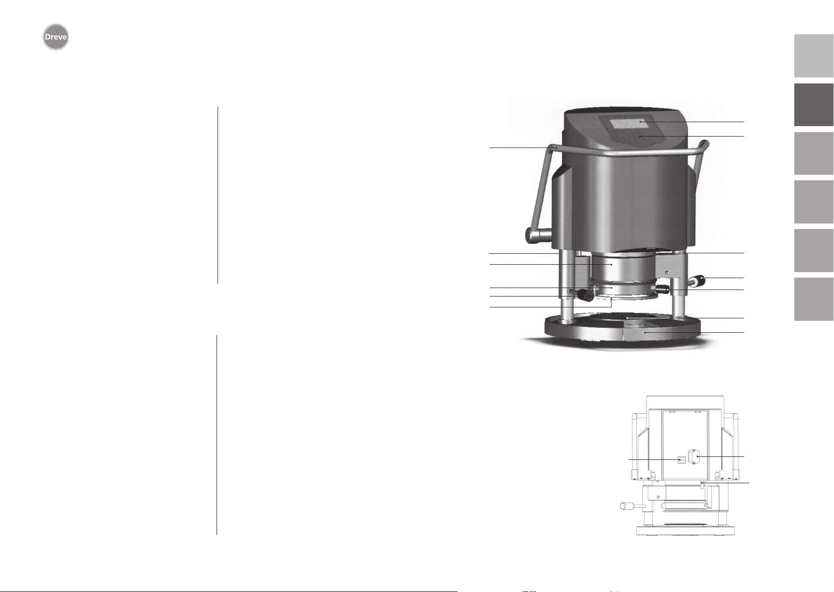
No. Description
1 Scanner
2 Display
3 Key pad
4 Heating element
5 Heating handle
6 Nub plate and insert bowl
7 Drawer for granules
9 Compressed air supply
10 Handle plate reception
11 Plate reception
12 Ventilation valve
13 Tension ring
33 Mains supply/fuse carrier
34 Activation lever
43 Main switch
43
2
3
1
5
12
6
7
33
nederlands
9
30
31
Page 17
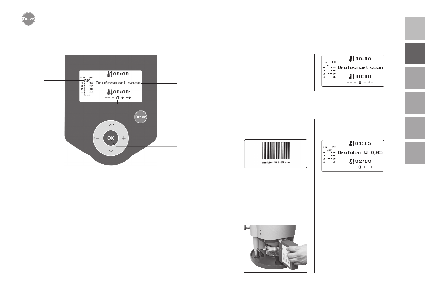
Drufosmart scan
7. Display 8. Operation
Turn the unit on by means of the main
switch (43) at the back of the unit. By
this the scanner (1) and the display
a
g
h
b
c
(2) at the front of the unit will be activated. An acoustic signal shows that
the unit is ready for operation; the display will show the name of the machine
Drufosmart scan.
8.1 Scan modus
deutschenglishfrançaisespañolitaliano
i
j
No. Description
a indication of heating time
b indication of product name and material strength
c indication of cooling time
d change of menu items (backwards)
e change of time indications (upwards)
f confirmation key / start button heating
g indication of pressure inside piston
h control indication for individual time modifications
d
e
f
Every outer package of Dreve thermoforming blanks is labelled with a barcode label.
This barcode contains the encrypted
product name, material strength as
well as the individual heating and cooling times.
In order to scan the material data with
the Drufosmart scan the barcode is to
be placed as centrally and evenly as
possible onto the scan field (1).
There will be an acoustic signal for the
confirmation of the data capture and
the display will show all necessary data.
nederlands
Info
The light emanating from the
scanner is harmless. Even in case
of direct eye contact it has no negative impact!
After 15 min. without use the
scanner turns off automatically. By
pressing the OK key it can be reactivated again. During an active
thermoforming process the scanner is deactivated. After termination of the process it will be reactivated automatically.
32
33
Page 18
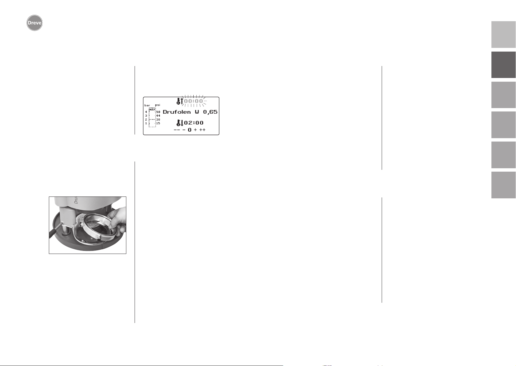
Drufosmart scan
8.2 Pressure adjustment
deutschenglishfrançaisespañolitaliano
The incoming pressure from the compressor must not exceed 10 bars! If necessary, assemble a pressure reducing
valve into the supply resp. decrease the
total pressure of the compressor.
The working pressure of the Drufosmart
scan is 4 bars (58 psi). The pressure
is controlled digitally and will be controlled permanently.
8.3 Start of programme
In order to start the selected programme, put a blank that corresponds
to the entered barcode resp. programming onto the plate reception (11) and
fix it by means of the tension ring (13).
The model can either be put onto the
nub plate (6) or fixed by taking out the
nub plate and embedding it into granules in the insert bowl (6a).
Info
For an optimum adaptation of the
blank towards the model always
place the models in a way that
the anterior teeth are directed
The effective pressure in the pressure
chamber during the thermoforming process can be controlled via the bar chart
(g) of the display.
towards the centre of the blank.
When using hard blanks it is recommended to embed the models into granules. Models that
are placed onto the nub plate
should not exceed a max. height
of 23 mm.
Swivel the plate reception inwards at
the handle (10) just up to the mechanical interlock in the centre of the unit.
Also swivel in the heating element (4)
at the corresponding handle (5) just up
to the mechanical interlock in the centre
of the unit. Close the ventilation valve
of the tension ring (12).
Press the OK key (f). There will be an
acoustic signal as confirmation for the
activation of the heating; the scanner
will turn off and the adjusted heating
time will elapse in the display.
Info
For safety reasons the quartz
radiator is equipped with a final
switch and only works in swivelled
in position after having started a
programme.
If the quartz radiator is swivelled
outwards after having started a
programme, the heating process
will be interrupted automatically.
The indication in the display (a)
will stop and show the remaining time. By swivelling the quartz
radiator back in the programme
will be re-activated.
8.4 Thermoforming
After the heating time has elapsed there
will be an acoustic signal; the heating
time in the display will be 00:00. The
heating will be switched off automatically. Pull the heating (4) at the handle
(5) away from the centre of the unit as
far as it will go with the right hand.
Then push the activation lever (34) with
the left hand downwards as far as it will
go. By pulling the heating handle (5)
again as far as it will go the pressure
chamber closes completely and pressurising of the piston will be carried out
automatically. This is confirmed by an
acoustic signal.
Attention! The swivelling housing of the heating element
reaches high temperatures.
Therefore it must not be touched
– even not for short moments.
After the adjusted time has
elapsed the indicator (a) in the
display will stop and count the
duration after termination of the
heating time. This process may be
stopped by successive thermoforming.
Info
For safety reasons the pressure
chamber can only be pressurised,
if it has been moved downwards
completely manually. In order
to protect the operating personnel securely against bruises of
the fingers, pressurising can only
be effected, if the unit is operated with two hands at the same
time (two-hand control). Always
make sure that no objects are in
the contact area between piston
and insert bowl while the piston
is closing!
nederlands
34
35
Page 19
Drufosmart scan
deutschenglishfrançaisespañolitaliano
9. Deviation to the rule
There will be an automatic pressurising
up to 4 bars. The pressure inside the
pressure chamber will be verified permanently by the electronics and regulated, if necessary. The display shows
the given cooling time (c) which then
counts down to 00:00.
8.5 Opening of the pressure chamber
In order to attain a complete cool down
of the thermoforming blank the valve
at the tension ring (12) is to be opened
slightly after 2/3 of the adjusted cooling
time. Through this the warm air inside
the piston will be released and replaced
by cool air due to the pressure regulation of the electronics. After the cooling time has elapsed there will be an
acoustic signal (indication in the display
(c) will blink).
Then swivel the pressure chamber into
its original position by leading back
the activation lever (34). Swivel out
the plate reception (11) at the corresponding handle (10) and remove tension ring and thermoformed result.
The display (2) will show the last used
programme; the scanning device (1) is
ready for a new thermoforming process.
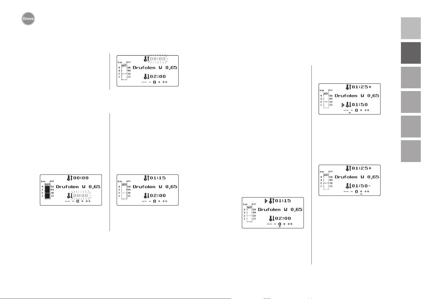
9.1 Modification of given times
Scanned times may be prolonged or
shortened individually, if required.
Info
The performance of the heating
might decrease slightly after 1000
operating hours. By prolonging
the heating times by 5–10 seconds
optimum thermoforming results
can be attained again. The times
given by the barcodes are average times and designed for general use. In case of extreme undercut areas or very high models a
prolongation of the heating time
can optimise the results.
After having scanned the pre-adjusted
material parameters (see paragraph
8.1) the heating time (1 x) or the cooling time (2 x) can be selected by pressing the menu key (j). There will be an
arrow in the display in front of the chosen time.
With the same working steps the cooling time can be modified in steps of
10 seconds by max. 70 seconds.
For identification of the modified
parameters the display will show a +
resp. a – sign. The degree of deviation
will be shown by a scale at the bottom
of the display.
Modified values have to be confirmed
by pressing the OK key (f).
nederlands
36
All further working steps correspond
to 8.2.
Pull the heating handle (5) again as
far as it will go and maintain it in this
position (approx. 2–3 seconds) until the
pressure is relieved.
The heating time can be modified positively and negatively in steps of 5 seconds. For this press the menu keys (e/i)
according to the key description. The
max. deviation from the scanned time
is 35 seconds.
37
Page 20
Drufosmart scan
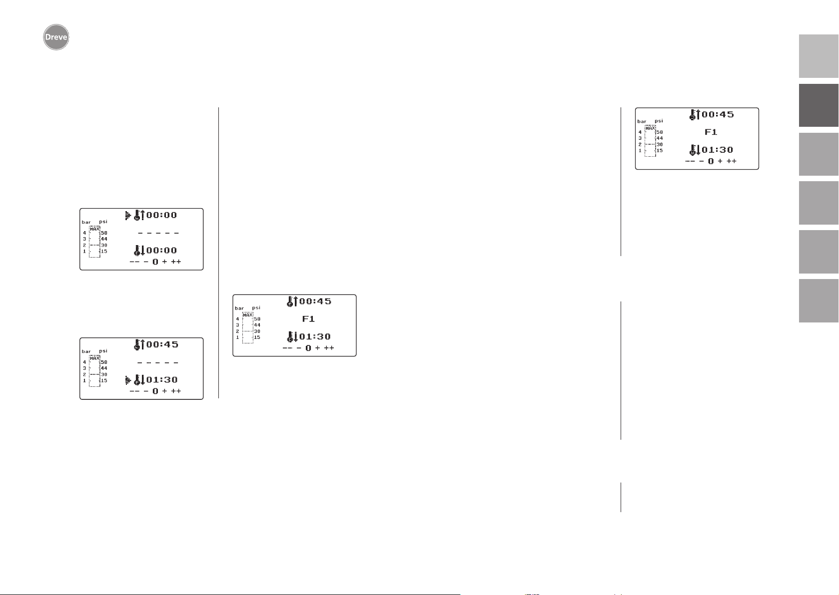
9.2 Creation and storage of manual time programmes 9.3 Calling of individual time programmes
deutschenglishfrançaisespañolitaliano
Up to three individual time programmes
may be created and stored for thermoforming foils that are not equipped with
a corresponding barcode.
Turn on the unit – the initial display
will be visible. When pushing the menu
key (j) one time the display will show
– – – – – at position b.
As described in point 9.1, push menu
key (j) and select the desired heating
time by the menu keys +/- (e/i). Following push menu key (j) again and enter
cooling time.
For single use confirm the two entered
values by pushing OK (f). Then go on
as described in point 8.2.
If the created time programme is to
be stored for repeated use, 3 memory
capacities (F1–F3) are available.
Do not confirm the created time programme by pushing OK, but press menu
key (j) again. The display will show F1
in position b, the entered times will be
taken over. The memory capacities F2
and F3 can be selected by pushing the
menu key (j) 2 resp. 3 times. Store the
times in the desired memory capacity
by pushing the OK key (f).
Then go on as described in point 8.2.
Turn on the unit – the initial display
will be visible. By pushing the menu
key (j) several times you may select one
after another:
a) enter modus
b) F1
c) F2
d) F3
By pressing the menu keys (d/j) you may
navigate arbitrarily between the a. m.
programme points. Confirm the selected
programme point with the OK key (f).
9.4
Plasticizing of blanks with unknown heating times
Create an individual time programme
with high heating and cooling times
(see point 9.2). Start the programme
(see point 8.2). You may test the
plasticization degree of the blank by
means of an edgeless metal instrument
(e. g. wax knife).
Info
The complete deformability of the
blank can only be tested at the
edges, as that is where warmth
will leak through the metal con-
Then go on as described in point 8.2.
tacts and the necessary flexibility
will be attained at last!
After the blank has attained the necessary flexibility initiate the thermoforming process (see point 8.4). The remaining heating time will be erased from
the display (a) and the adjusted cooling
time will be counted down (c).
The cooling time can be terminated at
any time by pulling the heating handle (5).
nederlands
38
9.5 Abort/termination of programme
During an active time programme the
key pad is deactivated. It is possible
to abort/terminate all actions of the
Drufosmart scan by pulling the heating handle (5) as far as it will go (for
approx. 3 seconds).
39
Page 21
Drufosmart scan
deutschenglishfrançaisespañolitaliano
9.6 Exceeding of entered heating/cooling times
After elapse of times adjusted regularly (display position a/c) there will be
an acoustic signal. The exceeded time
will be blinking in the display as control
mechanism.
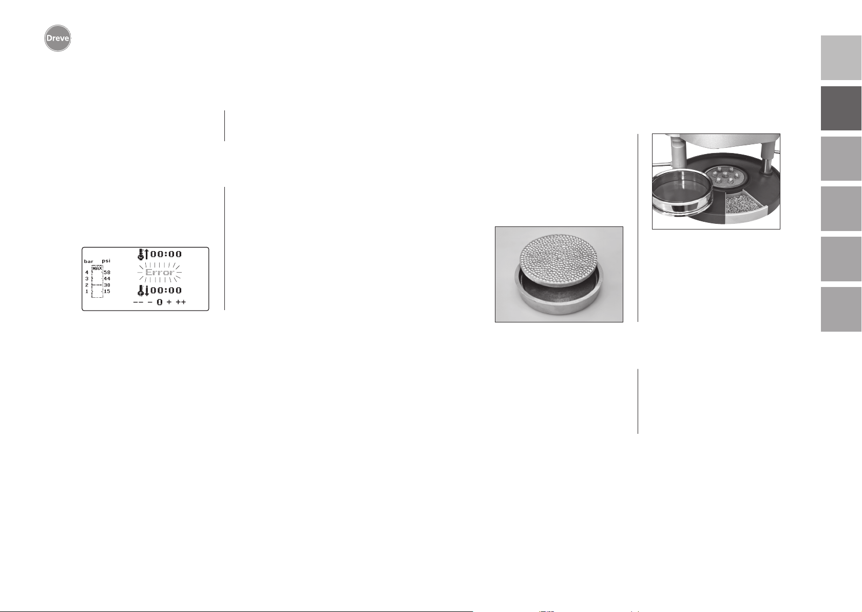
9.7 Entering a wrong barcode
If a barcode is scanned that does not
correspond to the programming of the
Drufosmart scan, four acoustic warning
signals will be heard and the display will
show ERROR at position b.
By scanning the correct barcode you
can proceed further, as described in
point 8.0.
10 Optional additional functions
10.1 Fabrication of cast form parts
With the K-7 insert it is possible to
thermoform up to 7 resin bases for
the crown and bridge technique at the
same time. Fix the single dies by means
of a flexible blocking out material (e.
g. Fillin) in the holes of the K-7 insert.
Remove the nub plate from the insert
bowl and replace it by the K-7 insert.
All further working steps as described
from point 7.1 on.
11. Care and maintenance
Generally disconnect the unit from
mains supply before executing care
and maintenance.
with a slightly humid sponge and a mild
cleaning liquid. Water and cleaning liquids must not get into the unit.
nederlands
40
Ideally cleaning is to be effected dryly
with a soft piece of cloth, if necessary
The O-rings should be greased regularly
with silicone grease.
41
Page 22
Drufosmart scan
deutschenglishfrançaisespañolitaliano
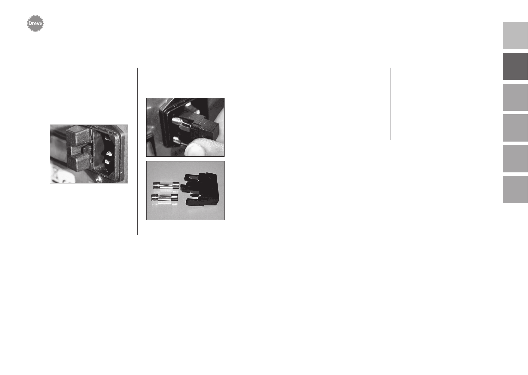
12. Exchange of fuses
Disconnect the unit from mains supply.
The fuse carrier is situated at the rear of
the unit, integrated in the mains supply.
In order to control or exchange the
fuses push the push catch of the carrier, keep it pressed and remove the
carrier from the unit.
Pull the defective fuse out of the clamp
carrier applying slight traction and
replace it by a new, equivalent one.
Important: Only use the fuse
strength indicated on the rear.
After exchanging the fuse insert the
fuse carrier into the housing applying
slight pressure until the fixation latches
noticeably.
13. General advice
Repairs on the Drufosmart scan units
may only be executed by experts. Disconnect the unit from mains supply at
any rate. Dreve company is only responsible for the safety, reliability and performance of the unit, if:
· the unit is exclusively used for the corresponding field of application.
· operation is only carried out by accordingly trained personnel.
14. Guarantee
The guarantee time amounts to two
years after the date of delivery. Guarantee is only accepted in case of material
or fabrication defects. The guarantee
obligation does not refer to natural
wear and tear or to damage occurring
after the transfer of risk due to improper
or unsuitable handling, excessive stressing, unsuitable operating material, and
chemical, electrochemical or electrical
influences of a nature not provided for
according to the contract. On improper
alterations, repairs or maintenance or
breach of seals carried out by the purchaser or third parties our warranty obligations and liability for consequences
caused thereby are rendered void.
· the unit is operated in accordance with
these working instructions.
· extensions, new adjustments, changes
or repairs are executed by persons
authorised by the company.
As we are currently developing our
products, we reserve the right for technical changes.
Liability
The right of the purchaser to bring
actions arising out of defects shall in
all cases be in lapse one year after the
date of delivery. The warranty obliga
tion does not refer to natural wear
and tear or to damage occurring after
the transfer of risk due to improper or
unsuitable handling, excessive stressing, unsuitable operating material, and
chemical, electrochemical or electrical
influences of a nature not provided for
according to the contract. On improper
alterations, repairs or maintenance or
breach of seals carried out by the purchaser or third parties our warranty obligations and liability for consequences
caused thereby are rendered void.
-
nederlands
42
43
Page 23
Drufosmart scan
15. Trouble shooting
deutschenglishfrançaisespañolitaliano
Problem
Unit does not work
Main breaker on,
electronics show no
function
Piston cannot move
downwards
Piston has moved
downwards, unit
does not take over
self-maintenance
Piston does not
move upwards
Electronics can be set,
but radiator does not
heat
Cause
Power line is not correct
Main breaker is off
Miniature fuse is defect
Electronics are out
of order
Heating is not swivelled
outwards
Electronics are out
of order
Wrong operation
of push button
Contact pressure has
not been relieved
Final switch is defect
Magnet valve or
electronics are defect
Heating element is not
swivelled-in completely
Micro-switch defect
Aid
Control power supply
Switch on main breaker
Check miniature fuse
and exchange it,
if necessary
Electronics have to be
exchanged by an expert
Swivel heating outwards
Electronics have to be
checked by an expert
Pull push button
for 3 sec.
Relieve contact
pressure, see working
instructions
Final switch has to be
exchanged by an expert
Unit has to be
controlled by an expert
Swivel the heating
element in correctly
Micro-switch has to be
exchanged by an expert
Problem
Heating time elapses,
but radiator does not
heat
Heating time elapsed,
blank is not plasticised
sufficiently
Scanner not active
Unit does not reach the
pre-adjusted pressure
Unit makes fizzy sounds
during thermoforming
Cause
Quartz radiator defect
Temperature monitor
was activated
Lifetime of quartz
radiator exceeded
Heating time was
too short
Wrong heating time
was chosen
Scanner in sleeping
position
Scanner or electronics
defect
Line pressure too low
Ventilation valve
not closed
Tension ring has been
placed wrongly into
plate reception
Connection hose
leaky between valve
and cylinder
Aid
Exchange quartz
radiator
Exchange temperature
monitor
Exchange quartz
radiator
Prolong heating time
by 5–10 sec.
Scan correct barcode
Press OK key briefly
nederlands
Electronics have to be
checked by an expert or
exchanged, if necessary
Increase line pressure
Close ventilation valve
Put tension ring into
correct position
Unit has to be
controlled by an expert,
connection hose
has to be exchanged,
if necessary
44
45
Page 24
Drufosmart scan
16. Spare part list
deutschenglishfrançaisespañolitaliano
No. Description
5 Heating handle D6505519
6 Insert bowl with nub plate 50591/50592
7 Drawer for granules 5565
9 Compressed air connection, complete D6505536SM
10 Handle plate reception D6505519
11 Plate reception D6505512
12 Ventilation valve 50761
13 Tension ring D50038
14 Cover glass scanner 1429
15 Scanner D6505541X1
17 Housing red D65555RSCAN
Housing silver D65555SSCAN
19 Micro-switch 55790
20 Heating housing D6505513
21 Quartz-infrared-radiator D6505542
22 Temperature monitor 5542
23 Pillar heating element 55773
24 Power supply D6505571
25 Magnetic valve 5202124
26 Cylinder 52020
27 Display foil, adhesive 55810
28 Limit plate reception D6555344
29 Support plate reception D6505514
30 Pillar plate reception 55772
31 Bottom plate D6505511
33 Mains supply/fuse carrier 51208
34 Activation lever D65885
35 Connector lever/axis D65017
36 Bushings 55708
37 Final switch activation lever 5521
38 Final switch heating 55790
39 Recuperating spring 55861/55862
40 Lever axis D6555847
43 Main switc 50841
without drawing no.
Power cord Europe 51021
Power cord England 51284
Power cord America 51283
Electronics incl. display, key pad, connection cable D6505530
Fuse F3.15 AT 51321
O-ring 112 x 3 mm 51077
Cable harness complete 55520
Limit heating element D65016
Control Card D6505572X1
nederlands
46
47
Page 25
Drufosmart scan
deutschenglishfrançaisespañolitaliano
1. Description de l’appareil
La Drufosmart scan est une thermoformeuse de pression d’usage universel, pour l’opération journalière dans
le laboratoire dentaire. Un mode scan
rend possible d’entrer directement de
noms de produits, épaisseurs de plaques
ainsi que des temps de chauffage et
refroidissement individuelles, grâce à
un code barré, qui se trouve sur chaque
paquet de plaques.
Une pression de formage fixe de 4 bars
en connexion avec une feuille formant
de manière verticale, garantissent des
résultats absolument précis.
2. Données techniques
Dimensions (H x L x P): 420 x 320 x 290 mm
Poids: 15 kg
Voltage: 100–240 V / 50–60 Hz
Puissance max.: 115 V–270 W, 230 V–315 W
Fusible de l’appareil: T 3,15 A
Pression d’opération: 4 bars
Pression d’opération min.: 2 bars
Pression du conduit max.: 10 bars
4. Avis de sécurité
Attention! Lire attentivement ces indications avant le branchement et la mise en
marche de l’appareil. L’assurance du fonctionnement et des fonctions de l’appareil ne
peuvent être seulement garanties lorsque les instructions concernant la sécurité ainsi
que la protection des accidents mentionnées dans le mode d’emploi ont été suivies.
1. L’appareil doit être seulement utilisé
d’après la description du mode d’emploi. Nous déclinons toute responsabilité pour des dommages dus à un
emploi faux ou mal interprété.
2. L’appareil doit être placé à une place
assez stable pour le poids d’opération
d’environ 15 kg et à niveau plat.
3.
Pour éviter la pénétration d’eau dans
la machine (p. ex. eau d’arrosage), la
machine doit être placée dans un endroit
sec.
4.
Ne stockez pas des substances
inflammables dans l’endroit de la
machine.
5. La tension donnée sur la plaque
signalétique doit correspondre avec la
tension sur la source de courant.
6. Brancher l’appareil à une prise de
courant avec prise de terre. Ne jamais
toucher la prise de courant avec des
mains humides.
7. Utilisateur autorisé: L’opérateur de la
machine doit mettre le mode d’emploi à
la disposition d’utilisateur et doit s’assurer, que celui-ci l’avait lu et compris.
Seulement après cela l’utilisateur doit
mettre la machine en opération.
8. Contrôler si état ainsi que sécurité de
service de l’appareil sont conformes. Si
ce n’est pas le cas, l’appareil ne doit pas
être utilisé et doit être marqué.
9. La pression du conduit ne doit pas
excéder 10 bars.
10. Ne faire pénétrer aucun objet dans
l’appareil.
11. Ne pas bloquer les éléments d’opération de l’appareil.
12. Ne pas bloquer le piston descendant.
13. Ne pas empoigner sous le piston
descendant.
14. La carrosserie tournante du radiateur atteint des températures élevées
durant l’opération. Pour cela il ne faut
pas la toucher, même pas pour des
moments courts.
15.
Si l’appareil n’est pas utilisé, veuillez
le débrancher.
16. Plaques et autocollants doivent
toujours être lisibles et ne doivent pas
être retirés.
nederlands
48
49
Page 26
Drufosmart scan
deutschenglishfrançaisespañolitaliano
6. Eléments de fonction
17. Avant d’entreprendre soins et net-
toyage de l’appareil ou bien vouloir
changer des pièces, il faut absolument
le débrancher.
18. Ouverture de l’appareil et réparations ne doivent être effectués que par
des spécialistes autorisés.
19. Il ne doit être employé qu’accessoires et pièces de rechange autorisés par le fabricant. Pour dommages
produits par l’emploi d’articles non
conformes nous déclinons toute responsabilité.
5. Mise en marche
Avant de mettre la machine en marche,
assurer, que la tension donnée sur la
plaque signalétique correspond avec la
tension sur la source de courant.
Connector l’appareil avec un compresseur d’air comprimè. Pour cela, enficher
le tuyau de pression dans le branchement d’air comprimé (9) en excédant
une petite résistance. Donc, le tuyau
est fixé automatiquement. Pour enlever le tuyau de pression presser le ring
bleu vers le haut et retirer le tuyau vers
le bas.
La pression du conduit ne doit pas
excéder 10 bars.
Mettre le câble du réseau dans la fiche
femelle (33) et créer une connexion
avec la fiche Euro / USA.
20. Des transformations arbitraires et
modifications ne sont pas permises pour
raisons de sécurité.
21. Il faut absolument observer les
conditions d’opération et entretien, qui
figurent dans ce mode d’emploi. Durant
le travail avec la Drufosmart scan il faut
également observer des prescriptions
de prévention des accidents générales.
Important: Avant de mettre la machine
en marche la première fois, il faut absolument lire le mode d’emploi soigneusement. S’il y a des problèmes de compréhension, veuillez contacter votre dépôt
responsable ou la société Dreve Dentamid GmbH, si nécessaire.
Contenu de livraison
1 Drufosmart scan
1 tiroir pour granulés
1 insert et plaque de cône
1 bague de tension avec valve
de ventilation
1 assortiment de feuilles de base
1 câble de réseau
1 tuyau de pression avec douilles
de tuyau et couplage rapide
1 mode d’emploi en 6 langues
34
9
4
13
10
11
N°. Désignation
1 Scanner
2 Display
3 Clavier
4 Elément de chauffage
5 Poignée de chauffage
6 Plaque de cône et insert
7 Tiroir pour granulés
9 Branchement d’air comprimé
10 Poignée support de plaques
11 Support de plaques
12 Valve de ventilation
13 Bague de tension
33
Branchement au secteur / porte-fusible
34 Levier d’activation
43 Interrupteur principal
2
3
1
5
12
6
7
43
33
9
nederlands
50
51
Page 27
Drufosmart scan
7. Display 8. Opération
Allumer l’interrupteur principal (43) au
dos de l’appareil, le scanner (1) et le
display (2) au front seront activés. Un
a
g
b
c
signal acoustique indique, que la machine
est prête à l’usage, le display montre le
nom de l’appareil Drufosmart scan.
deutschenglishfrançaisespañolitaliano
h
i
j
N°. Description
a indication du temps de chauffage
b indication du nom du produit et épaisseur de la feuille
c indication du temps de refroidissement
d changer des points du menu (en arrière)
e modification de temps (vers le haut)
f interrupteur de confirmation / interrupteur „start“ du chauffage
g indication de pression dans le piston
h indication de contrôle pour des modifications de temps individuelles
i modification de temps (vers le bas)
j changer des points du menu (en avant)
8.1 Mode scan
Chaque paquet de feuilles de thermo-
d
e
f
formage Dreve est équipé avec une étiquette code barré.
Ce code barré contient de manière chiffrée le nom du produit, l’épaisseur ainsi
que des temps de chauffage et refroidissement individuelles.
Pour entrer les données du produit dans
la Drufosmart scan, le code barré doit
être placé droitement et le plus central
possible sur le champ du scanner (1).
Il y aura un signal acoustique, qui
confirme l’enregistrement des données
et le display montrera toutes données
nécessaires.
nederlands
Infos
La lumière du scanner n’est pas
dangereuse et n’a pas d’influence
négative, même en cas de vue
directe!
Après 15 min. sans usage, le scanner s’éteint automatiquement.
En poussant le bouton OK, on le
peut réactiver. Durant un processus de thermoformage le scanner
est désactivé. Après terminaison
du processus, il se met en marche
automatiquement.
52
53
Page 28
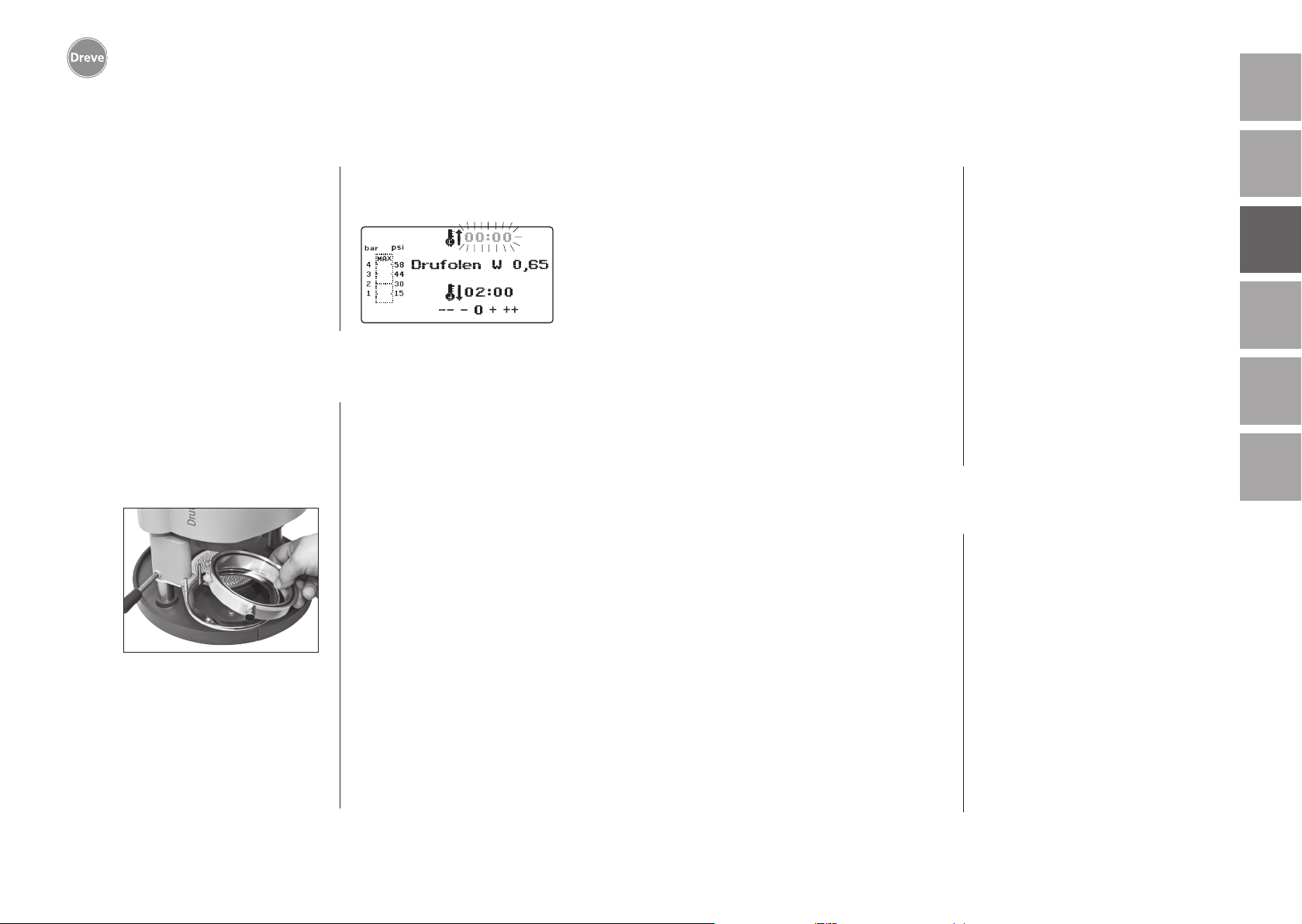
Drufosmart scan
8.2 Ajustement de pression
deutschenglishfrançaisespañolitaliano
L’alimentation de pression du compresseur ne doit pas dépasser 10 bars! Si
nécessaire, monter une valve de réduction dans l’alimentation resp. baisser la
pression totale du compresseur.
La pression d’opération de la Drufosmart
scan s’élève à 4 bars (58 psi). Celle-ci
est commandée de manière digitale et
contrôlée constamment. Il est possible
de contrôler la pression réelle durant
le processus de thermoformage dans
le diagramme de colonne (g) du display.
8.3 Mise en marche du programme
Pour mettre en marche le programme
choisi, mettez une feuille correspondante au code barré resp. correspondante à la programmation dans le support de plaques (11) et fixez-la à l’aide
de la bague de tension (13).
Soit on met le modèle sur la plaque
de cône (6), soit on enlève la plaque
de cône et fixe le modèle à l’aide des
granulés directement dans l’insert (6a).
Infos
Pour obtenir une adaptation optimale de la feuille vers le modèle, toujours fixez les modèles de manière,
que les dents antérieures montrent
vers le centre de la feuille. En cas des
feuilles dures, nous recommandons
d’enrober les modèles dans les granulés. Si on met les modèles sur la
plaque de cône, leur hauteur ne doit
pas dépasser 23 mm.
Tournez le support de plaques à l’aide
de la poignée (10) jusqu’à l’arrêt mécanique dans le centre de l’appareil. Egalement tournez le radiateur (4) à l’aide
de la poignée (5) jusqu’à l’arrêt dans le
centre de l’appareil. Fermez la valve de
ventilation de la bague de tension (12).
Poussez le bouton OK (f). Il y aura un
signal acoustique pour confirmer l’activation du chauffage. Le scanner s’éteint
et dans le display on peut voir le temps
de chauffage ajusté expirer.
Infos
Pour des raisons de sécurité le
radiateur à quartz est équipé avec
un interrupteur fin de course et ne
fonctionne qu’en position tournée
vers l’intérieur après le commencement d’un programme.
Si le radiateur à quartz sera tourné
vers l’extérieur dans la phase de
chauffage active, le processus de
chauffage sera interrompu automatiquement. L’indication dans le
display (a) termine et montre la
valeur résiduelle. Par tourner le
radiateur à quartz vers l’intérieur
encore une fois le programme sera
réactivé.
8.4 Thermoformage
Après terminaison du temps de chauffage il y aura un signal acoustique, le
temps de chauffage dans le display sera
00 : 00. Le chauffage s’éteint automatiquement. Poussez le chauffage (4) à
la poignée (5) avec la main droite complètement vers l’extérieur.
Puis, poussez le levier d’activation
(34) avec la main gauche jusqu’à l’arrêt vers le bas. En poussant la poignée
(5) encore une fois jusqu’à l’arrêt, la
chambre de pression se ferme complètement et la mise en pression aura lieu
automatiquement dans le piston. Il y
aura un signal acoustique pour la confirmation de la mise en pression.
Attention ! La carrosserie tournante du radiateur atteint des
températures élevées durant
l’opération. Pour cela il ne faut
pas la toucher, même pas pour
des moments courts.
Après le temps programmé a expiré,
l’indication (a) du display clignote
et compte la durée après la terminaison du temps de chauffage. Ce
processus peut être interrompu par
un processus de thermoformage
ultérieur.
nederlands
Infos
Pour raisons de sécurité, la
chambre de pression sera seulement alimentée de l’air comprimé,
au cas où celle-ci ait baissé complètement manuellement. Pour
protéger le personnel opérant
la machine sûrement contre des
ecchymoses des doigts, la mise
en pression peut seulement être
activée, si l’appareil est opéré
avec deux mains en même temps
(contrôle de deux mains). Toujours
observer, qu’il n’y a pas d’objets
dans la zone de contact entre le
piston et l’insert durant la fermeture du piston!
54
55
Page 29
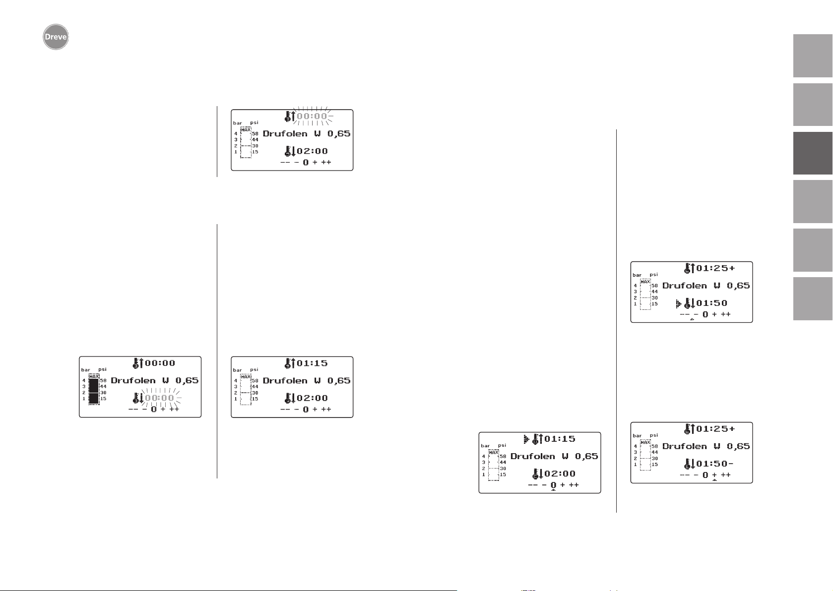
Drufosmart scan
deutschenglishfrançaisespañolitaliano
9. Anomalies
La pression s’élève automatiquement
à 4 bars. La pression dans la chambre
de pression sera contrôlée constamment par l’électronique et modifiée, si
nécessaire. Le display montre le temps
de refroidissement fixe (c) et compte en
arrière vers 00 : 00.
8.5 Ouverture de la chambre de pression
Pour atteindre un refroidissement complet de la feuille de thermoformage, la
valve à la bague de tension (12) doit
être ouverte légèrement après 2 / 3 du
temps de refroidissement ajustée. Par
cela l’air chaude dans le piston fuite
et sera remplacé par l’air froide, grâce
à la régulation de pression par l’électronique. Après le temps de refroidissement a expiré, il y aura un signal
acoustique (indication dans le display
(c) clignote).
Pousser la poignée du chauffage (5)
encore une fois jusqu’à l’arrêt et la
maintenir dans cette position jusqu’à
ce que la pression soit diminuée (environ 2–3 secondes).
Ensuite mettre la chambre de pression
dans sa position originale en retourner le levier d’activation (34). Tourner
le support de plaques (11) à l’aide de
la poignée (10) vers l’extérieur, enlever la bague de tension et le résultat
thermoformé.
Le display (2) montre le programme utilisé dernièrement, le scanner (1) est prêt
pour un nouveau processus de thermoformage.
9.1 Ajustement manuel des temps préprogrammés
Des temps scannés peuvent être prolongés ou raccourcies individuellement,
si nécessaire.
Infos
La performance du chauffage peut
devenir un peu plus faible après
1000 heures d’opération. Par
prolonger les temps de chauffage par 5–10 secondes, on peut
atteindre des résultats de thermoformage optimaux. Les temps
préprogrammés par le code barré
sont des valeurs moyennes pour
l’usage général. En cas de cavités extrêmes ou des modèles très
hautes, une prolongation des
temps de chauffage peut optimiser les résultats.
Après avoir scanné les paramètres
du produit (voir chapitre 8.1) on peut
sélectionner le temps de chauffage ou
temps de refroidissement par pousser
sur le bouton menu (j) (1 x pour chauffage, 2 x pour refroidissement). Dans
le display il y aura une flèche avant le
temps choisi.
Le temps de chauffage se laisse modifier
positivement et négativement en étapes
de 5 secondes. Pour cela, poussez les
touches menu (e / i) conformément à la
désignation des touches. La déviation
maximale du temps scanné s’élève à
35 secondes.
Avec les mêmes étapes de travail les
temps de refroidissement se laissent
varier en étapes de 10 secondes, en
maximum de 70 secondes.
Pour marquer les paramètres modifiés
le display ajoute un + resp. un – après
l’indication en question. Le niveau de
déviation sera montré par une échelle
en bas du display.
Les valeurs modifiées doivent être
confirmées par la touche OK (f).
nederlands
56
Toutes les autres étapes de travail
comme décrit à partir du chapitre 8.2.
57
Page 30
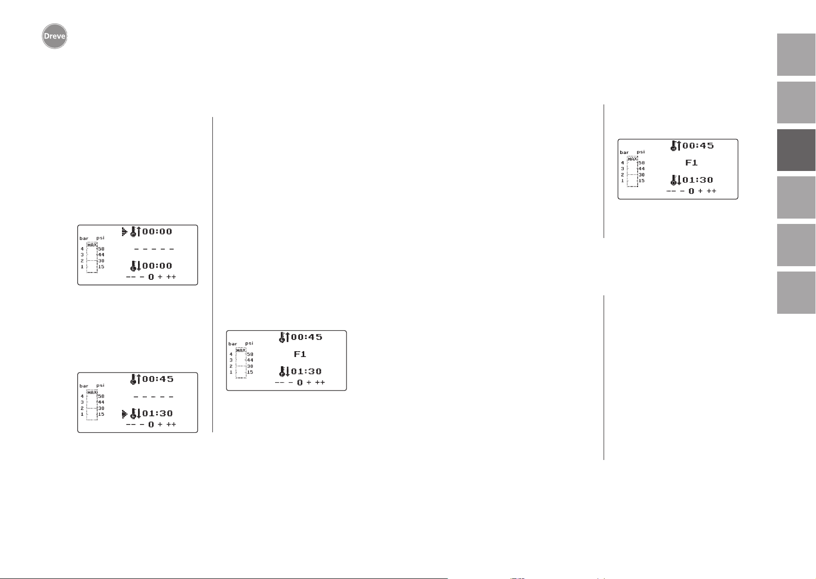
Drufosmart scan
deutschenglishfrançaisespañolitaliano
9.2 Création et enregistrement manuels des programmes
de temps
Pour des feuilles de thermoformage,
qui ne sont pas équipées avec un code
barré, on peut entrer et enregistrer
jusqu’à trois programmes de temps
individuels.
Mettez la machine en marche; il y aura
le display original. En poussant une fois
sur la touche menu (j) le display montrera en position b – – – – –.
Comme décrit en point 9.1, poussez
la touche menu (j) et sélectionnez la
valeur désirée pour le temps de chauffage par les touches + / - (e / i). Puis,
poussez encore une fois la touche menu
(j) et sélectionnez le temps de refroidissement.
Pour usage unique, simplement confirmez ces deux valeurs avec la touche OK
(f). Puis, suivez la description à partir
du chapitre 8.2.
Si vous désirez de sauvegarder le programme de temps pour usage ultérieur,
vous pouvez sélectionner entre trois
places de mémoire (F1–F3).
Pour cela, ne confirmez pas le programme de temps avec OK, mais poussez la touche menu (j) encore une fois.
Le display montre F1 en position b, les
temps entrés seront enregistrés. On
peut choisir les places de mémoire F2
et F3 en poussant la touche menu (j)
deux resp. trois fois. Sauvegardez les
temps sous les places de mémoire en
poussant la touche OK (f).
Puis, suivez la description à partir du
chapitre 8.2.
9.3 Se servir des programmes de temps individuels
Mettez la machine en marche ; il y aura
le display original. En poussant plusieurs fois sur la touche menu (j) vous
pouvez sélectionner l’un après l’autre:
a) le mode d’enregistrement
b) F1
c) F2
d) F3
Avec les touches menu (d / j) vous pouvez naviguer conformément à votre
désir entre les points du programme
9.4
Plastification de feuilles avec un temps de chauffage
mentionnés en haut. Confirmez le point
du programme désiré avec la touche
OK (f).
Puis, suivez la description à partir du
chapitre 8.2.
inconnu
Créez un programme de temps individuel avec des temps de chauffage et
refroidissement hautes (voir point 9.2).
Mettez le programme en marche (voir
point 8.2). Vous pouvez tester le degré
de plastification avec un instrument
métallique émoussé (p. ex. couteau
de cire).
Infos
Il faut tester la déformabilité
complète au bord, comme c’est
là où la chaleur s’échappe par
les contacts métalliques et pour
cela la flexibilité nécessaire sera
atteinte le plus tard !
Après la flexibilité nécessaire est
atteinte, exécutez le processus de thermoformage (voir point 8.4). Le temps
résiduel de chauffage sera effacé de
l’indication du display (a) ; le temps de
refroidissement programmé sera montré
comptant en arrière (c).
On peut toujours interrompre la phase
de refroidissement en poussant la poignée du chauffage (5).
nederlands
58
59
Page 31
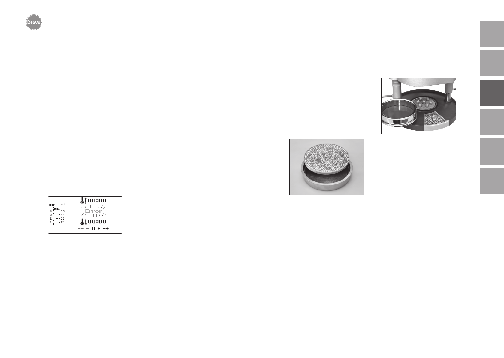
Drufosmart scan
deutschenglishfrançaisespañolitaliano
9.5 Arrêt / terminaison du programme
Durant un programme actif le clavier
est inactivé. L’arrêt / terminaison de
toutes actions est possible en poussant
la poignée (5) jusqu’à l’arrêt (approx.
3 secondes).
9.6 Dépassement des temps de chauffage / refroidissement enregistrés
Après terminaison des temps enregistrés régulièrement (position de display
a / c) il y aura un signal acoustique.
Comme mécanisme de contrôle, le
temps dépassé sera montré clignotant
dans le display.
9.7 Enregistrement d’un code barré faux
Si un code barré sera scanné, qui ne
correspond pas à la programmation
de la Drufosmart scan, il y aura quatre
signales d’alarme et le display montre
le mot ERROR (erreur) en position b.
En scannant le code barré correcte on
peut suivre les étapes décrites à partir
de point 8.0.
10 Fonctions additionnelles en option
10.1 Production de chapes
L’insert K-7 rend possible de thermoformer jusqu’à 7 bases en résine pour
la technique de couronnes et bridges
en même temps. Fixez les moignons
singles avec un matériau de blocage
flexible (p. ex. Fillin) dans les espaces
de l’insert K-7 désignées à cet effet.
Enlevez la plaque de cône de l’insert et
remplacez-la par l’insert K-7.
Toutes les autres étapes de travail
comme décrit à partir du chapitre 7.1.
11. Soin et entretien
Débrancher l’appareil du réseau avant
d’exécuter des travaux de soin et entre
tien.
-
L’eau et les agents de nettoyage ne
doivent pas pénétrer à l’intérieur de
l’appareil.
nederlands
60
Le nettoyage se fait en sec avec un tissu
souple, si nécessaire avec une éponge
humide et un agent de nettoyage doux.
Les anneaux d’étanchéité doivent être
régulièrement traités avec de la graisse
siliconée.
61
Page 32
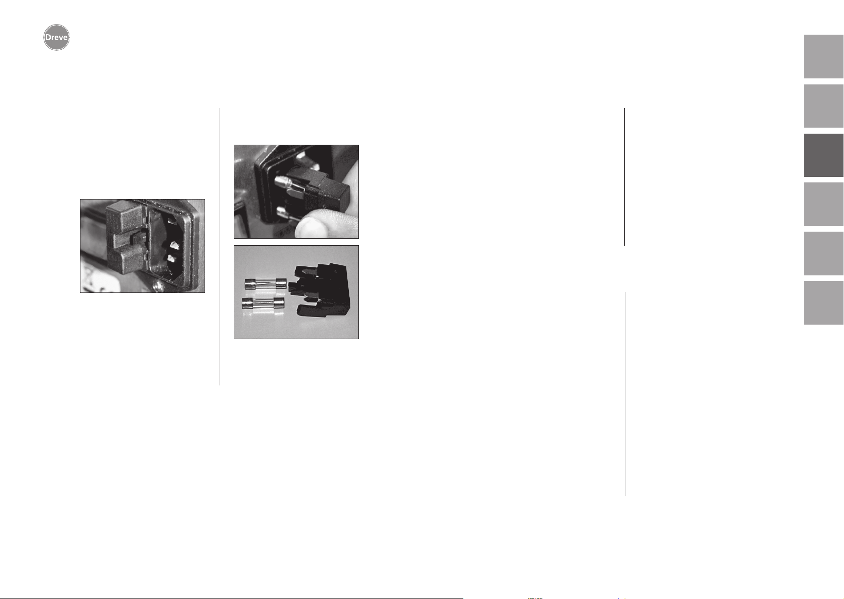
Drufosmart scan
deutschenglishfrançaisespañolitaliano
12. Changement de fusibles
Séparer le conduit du réseau. Le portefusible se trouve au dos de l’appareil,
intégré dans l’alimentation sur secteur.
Pour changer ou contrôler le fusible,
poussez le bouton-poussoir du portefusible, le maintenir poussé et défaire
le porte-fusible de l’appareil.
Tirez le fusible défectueux prudemment
du porte-borne et remplacez-le par un
fusible équivalent.
Important: Seulement utilisez
les fusibles indiqués au dos de
l’appareil.
Insérez le porte-fusible dans l’appareil
avec une pression légère jusqu’à ce que
la fixation s’enclenche sensiblement.
13. Avis généraux
Réparation et installation de l’équipement de la Drufosmart scan doivent
être faites par des experts autorisés.
Ne pas oublier d’interrompre le courant. La maison Dreve est seulement
responsable pour la sûreté, la garantie
et le rendement de l’appareil, lorsque:
· celui-ci est utilisé pour l’emploi qui
est prévu.
· l’utilisation n’a lieu que par des personnes ayant l’habitude de se servir
de l’appareil.
14. Garantie
La durée de la garantie se prescrive au
bout de deux ans à partir de la livraison.
La garantie ne concerne ni l’usure naturelle ni les dommages qui surviennent
après le transfert du risque à la suite
de manipulation défectueuse ou non
conforme aux rescriptions, de sollicitation extrême, de moyens d’exploitation inadéquats et influences chimiques,
électrochimiques ou électriques qui ne
sont pas présupposées par le contrat.
Les modifications effectuées incorrectement par l’auteur de la commande ou
par un tiers ou les travaux de réparation
et d’entretien, ainsi que la destruction
de plombages éliminent les droits de
garantie.
· l’appareil est utilisé d’après la description exacte de ce mode d’emploi.
· agrandissement, nouveau branchement, modification ou réparation sont
exécutés par des ateliers prévus à cet
effet.
Du fait que nos produits sont en développement permanent, il se trouve tou
jours la possibilité d’annoncer de nouveaux détails techniques.
Responsabilité de défauts
Les droits résultant des défauts se
prescrivent au bout d’un an à partir
de la livraison. Les droits résultant des
défauts ne concernent ni l’usure naturelle ni les dommages qui surviennent
après le transfert du risque à la suite
de manipulation défectueuse ou non
conforme aux prescriptions, de sollicitation extrême, de moyens d’exploitation
inadéquats et d’influences chimiques,
électrochimiques ou électriques qui ne
sont pas présupposées par le contrat.
Les modifications effectuées incorrectement par l’auteur de la commande ou
par un tiers ou les travaux de réparation
et d’entretien, ainsi que la destruction
de plombages éliminent les droits résultant des défauts.
-
nederlands
62
63
Page 33
Drufosmart scan
15. Conseils en cas de panne
deutschenglishfrançaisespañolitaliano
Panne
L’appareil ne montre
aucune fonction
L’interrupteur principal est
allumé, l’électronique ne
montre aucune fonction
Le piston ne se laisse
pas descendre
Le piston est
descendu, l’appareil
ne se maintient pas
Le piston ne s’élève pas
Cause
Connexion avec le
réseau n’est pas correct
L’interrupteur principal
est éteint
Fusible est défectueux
Electronique est
défectueuse
Chauffage n’a pas été
pivotée vers l’extérieur
Electronique est
défectueuse
Opération fausse du
bouton-poussoir
Pression de formage n’a
pas été diminuée
Depannage
Contrôler connexion
avec le réseau
Allumer l’interrupteur
principal
Vérifier le fusible et
l’échanger, si nécessaire
Un expert doit vérifier
l’électronique
Pivoter le chauffage
vers l’extérieur
Un expert doit vérifier
l’appareil
Tirer le bouton-poussoir
pendant 3 secondes
Diminuer pression de formage, voir mode d’emploi
Panne
Temps de chauffage se
termine, mais l’appareil
ne chauffe pas
Temps de chauffage
est terminé, mais la
feuille n’est pas
plastifiée suffisamment
Scanner ne s’allume pas
L’appareil n’atteint pas
la pression ajustée
Cause
Radiateur à quartz
est défectueux
Garde de température
a déclenché
Durée de vie du radiateur
à quartz a dépassé
Temps de chauffage a
été trop court
Temps de chauffage
choisi est faux
Scanner en phase
de repos
Scanner ou électronique
sont défectueux
La pression dans le
conduit est trop faible
Depannage
Changer le radiateur
à quartz
Changer le garde de
température
Changer le radiateur
à quartz
Prolonger le temps de
chauffage par 5–10
secondes
Scanner le code barré
correct
Pousser l’interrupteur
OK brièvement
Un expert doit vérifier
l’électronique et
l’échanger, si nécessaire
Augmenter la pression
dans le conduit
nederlands
64
Electronique en fonction,
mais chauffage ne
marche pas
Interrupteur fin de
course est défectueux
Electrovanne ou électronique sont défectueuses
Radiateur n’est pas
tourné vers l’intérieur
complètement
Micromanipulateur
défectueux
Un expert doit changer
l’interrupteur fin de course
Un expert doit vérifier
l’appareil
Tourner radiateur
vers l’intérieur
complètement
Un expert doit changer
le micromanipulateur
L’appareil fait des
bruits sifflants durant
le processus de
thermoformage
La valve de ventilation
n’est pas fermée
La bague de tension
a été mise de manière
fausse dans le support
de plaques
Le tuyau de connexion
entre la valve et le
cylindre fuit
Fermer la valve
de ventilation
Placer la bague de
tension correctement
Un expert doit vérifier
l’appareil et changer
la pièce du tuyau, si
nécessaire
65
Page 34
Drufosmart scan
16. Liste de pièces détachées
deutschenglish
N°. Désignation
5 Poignée chauffage D6505519
6 Insert avec plaque de cône 50591/50592
7 Tiroir pour granulés 5565
9 Branchement d’air comprimé complet D6505536SM
10 Poignée support de plaques D6505519
11 Support de plaques D6505512
12 Valve de ventilation 50761
13 Bague de tension D50038
14 Couverture en verre scanner 1429
15 Scanner D6505541X1
17 Carrosserie rouge D65555RSCAN
Carrosserie argenté D65555SSCAN
19 Micromanipulateur 55790
20 Carrosserie du chauffage D6505513
21 Radiateur a quartz infrarouge D6505542
22 Garde de température 5542
23 Pilier élément de chauffage 55773
24 Alimentation électrique D6505571
25 Electrovanne 5202124
26 Cylindre 52019
27 Feuille du display, collante 55810
28 Arrêt support de plaques D6555344
29 Manche support de plaques D6505514
30 Pilier support de plaques 55772
31 Plaque de fond D6505511
33 Alimentation sur secteur / porte-fusible 51208
34 Levier d’activation D65885
35 Connecteur levier / axe D65017
36 Douilles 55708
37 Interrupteur fin de course du levier d’activation E5521
38 Interrupteur fin de course du chauffage 55790
39 Ressort de rappel 55861/55862
40 Axe de levier D6555847
43 Interrupteur principal 50841
sans n° de dessin
Cordon électrique Europe 51021
Cordon électrique Angleterre 51284
Cordon électrique Amérique 51283
Electronique, y inclus display, clavier, cordon de raccordement D6505530
Fusible F3,15 AT 51321
Bague d’étanchéité 112 x 3 mm 51077
Câble à tisser complet 55520
Tôle d‘arrêt du chauffage D65016
Carte commande D6505572X1
italiano español français
nederlands
66
67
Page 35
Drufosmart scan
deutschenglishfrançaisespañolitaliano
1. Descripción del equipo
El Drufosmart scan es un termoadaptador a presión universal para uso diario
en laboratorios dentales. Un dispositivo
de escáner integrado en el equipo permite la transmissión directa del nombre
del producto, el grosor de la plancha,
así como los tiempos individuales de
calentamiento y enfriamiento por medio
de un código de barras situado en cada
unidad de embalaje.
Una presión de moldeo fija de 4 bar en
combinación con la lámina de termoadaptación vertical asegura resultados
extremadamente precisos.
2. Características técnicas
Dimensiones (A x L x P): 320 x 420 x 290 mm
Peso: 15 kg
Alimentación: 100–240 V/50–60 Hz
Consumo máximo: 115V–270 W, 230 V–315 W
Fusible: T 3,15 A
Presión: 4 bar
Presión mínima de servicio: 2 bar
Presión máxima de servicio: 10 bar
4. Advertencias de seguridad
Atención! Lea estas indicaciones antes de conectar y poner en marcha el aparato. La
funcionalidad y seguridad del aparato sólo están garantizadas si se cumplen tanto los
requisitos de seguridad y prevención de accidentes exigidos por la legislación como las
indicaciones de seguridad recogidas en el manual de instrucciones.
1. El aparato debe ser utilizado únicamente de acuerdo con el presente
manual de instrucciones. Declinamos
cualquier responsabilidad por daños
debido a un uso y manejo incorrecto.
2. El aparato debe colocarse sobre una
base plana y suficientemente sólida
para soportar el peso operativo del
mismo de aproximadamente 15 kg.
3. Para evitar que entre agua en el
equipo (p. ej. salpicaduras de agua),
éste se deberá colocar en un entorno
seco.
4. No guarde materiales facilmente
inflamables en las inmediaciones del
equipo.
5. La tensión consignada en la placa
de características debe coincidir con la
tensión de la fuente de alimentación.
6. El aparato debe ser enchufado únicamente a una toma con conductor de
protección. No coger nunca el enchufe
de red con las manos mojadas.
7. Usuarios autorizados: el instalador
de la máquina debe facilitar al usuario
el acceso al manual de instrucciones y
asegurarse de que lo ha leído y com-
prendido correctamente. Sólo entonces podrá el usuario poner en marcha
el equipo.
8. Se debe asegurar el perfecto estado
funcional y de seguridad del aparato
antes de su uso. Si el estado no es perfecto abstenerse de utilizar el aparato e
indicarlo como corresponda.
9. La presión de la tubería de aire comprimido no debe superar los 10 bar.
10. No debe introducirse ningún objeto
en el interior del equipo.
11. No deben bloquearse los elementos
de manejo del equipo.
12. No se debe bloquear nunca el
émbolo de descenso.
13. No se debe tocar debajo del émbolo
de descenso.
14. La caja giratoria del calefactor
puede alcanzar temperaturas elevadas durante el funcionamiento y por
lo tanto no se debe tocar ni por un
instante.
15. El equipo se debe desconectar de
la red eléctrica si no se va a utilizar.
nederlands
68
69
Page 36
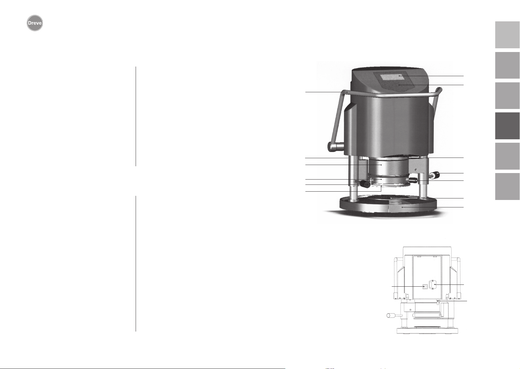
Drufosmart scan
deutschenglishfrançaisespañolitaliano
6. Elementos de función
16. Los rótulos y adhesivos deben ser
siempre bien legibles y no se deben retirar de su sitio.
17. El equipo debe desconectarse de la
red eléctrica antes de limpiarse, realizar
trabajos de mantenimiento o sustituir
alguna pieza.
18. El equipo sólo debe ser abierto y
reparado por personal especializado y
debidamente autorizado.
19. Sólo deben utilizarse recambios y
acesorios originales autorizados por el
fabricante. Declinamos toda responsabilidad por daños causados por el uso
de piezas no autorizadas.
20. Por motivos de seguridad, no están
permitidas las modificaciones o alteraciones por cuenta propia.
21. Se deben cumplir obligatoriamente
las condiciones de servicio y mantenimiento especificadas en este manual
de instrucciones. Al trabajar con el
Drufosmart se deben tener en cuenta
las normas generales de prevención de
accidentes.
5. Puesta en marcha/volumen de entrega
Antes de la puesta en marcha se debe
comprobar que la tensión de red indicada
en la placa de características coincide con
la de la fuente de alimentación.
Conexión del equipo a un compresor de
aire. Introduzca la manguera de presión
suministrada en la boquilla portatubo
(9) hasta que se enclava firmemente.
Así el tubo se fija automáticamente.
Para deshacer el tubo de presión empujar el aro azul hacia arriba y quitar el
tubo hacia abajo.
La presión de la tubería no debe
superar los 10 bar.
Inserte el cable de alimentación en la
toma de corriente del equipo (32) y
conéctelo a la red con el enchufe Euro/
USA.
Importante: Antes de poner en marcha el equipo por primera vez, lea detenidamente las instrucciones de uso. Si
tiene alguna duda en su comprensión,
consulte con el proveedor correspondiente o directamente con la empresa
Dreve Dentamid GmbH.
Volumen de entrega
1 Drufosmart scan
1 Cajón de granulados
1 Pieza de inserción y placa moteada
1 Anillo tensor con válvula de escape
1 Surtido básico de laminas
1 Cable de alimentación
1 Manguera de aire comprimido
incl. abrazaderas para tubo flexible
y acoplamiento rápido
1 Instrucciones de trabajo
(en 6 idiomas)
34
9
4
13
10
11
No. Denominación
1 Escáner
2 Pantalla
3 Teclado
4 Elemento calefactor
5 Mando calefacción
6
Placa moteada y pieza de inserción
7 Cajón de granulado
9
Alimentación de aire comprimido
10 Mando plato giratorio
11 Plato giratorio
12 Válvula de salide de aire
13 Anillo tensor
33
Conexión a red/soporte de fusible
34 Palanca de activación
43 Interruptor principal
43
2
3
1
5
12
6
7
33
nederlands
9
70
71
Page 37

Drufosmart scan
7. Pantalla 8. Manejo
Conecte el interruptor principal (43) en
la parte trasera del equipo, se activa el
escáner (1) y la pantalla (2) en el frontal.
a
g
b
c
Una señal acústica indica que el equipo
está listo para el funcionamiento, en la
pantalla aparece el nombre del equipo:
Drufosmart scan.
deutschenglishfrançaisespañolitaliano
h
i
j
No. Denominación
a Indicación del tiempo de calentamiento
b Indicación nombre del producto y grosor del material
c Indicación del tiempo de enfriamiento
d Cambio de opción del menú (hacia atrás)
e Modificación de indicaciones de tiempo (ascendente)
f Tecla de confirmación/inicio de calentamiento
g Indicación de presión interior del émbolo
h Indicación de control para modificaciones de tiempo individuales
i Modificación de indicaciones de tiempo (descendente)
j Cambio de opción del menú (hacia delante)
8.1 Modo escáner
En cada envoltorio exterior de láminas
d
e
f
de termoadaptación Dreve se encuentra una etiqueta de código de barras.
Este código de barras incluye de forma
cifrada el nombre del producto, el gro
sor del material, así como los tiempos
individuales de calentamiento y enfriamiento.
Para que se lean los datos del material en el Drufosmart scan, el código de
barras se debe mantener lo más centrado y recto posible en el escáner (1).
-
Como confirmación del registro de los
datos suena una señal de confirmación,
y en la pantalla se muestran todos los
datos necesarios.
nederlands
Información
La luz que emite el escáner es
inofensiva y no posee efectos
perjudiciales para la vista aunque
incida directamente en los ojos.
El escáner se desconecta automáticamente si no se utiliza durante
15 minutos. Para volver a activarlo
basta con pulsar la tecla „OK“.
Mientras hay un proceso de termoadaptación en marcha, el escáner permanece desactivado. Al
finalizar el proceso, se vuelve a
conectar automáticamente.
72
73
Page 38
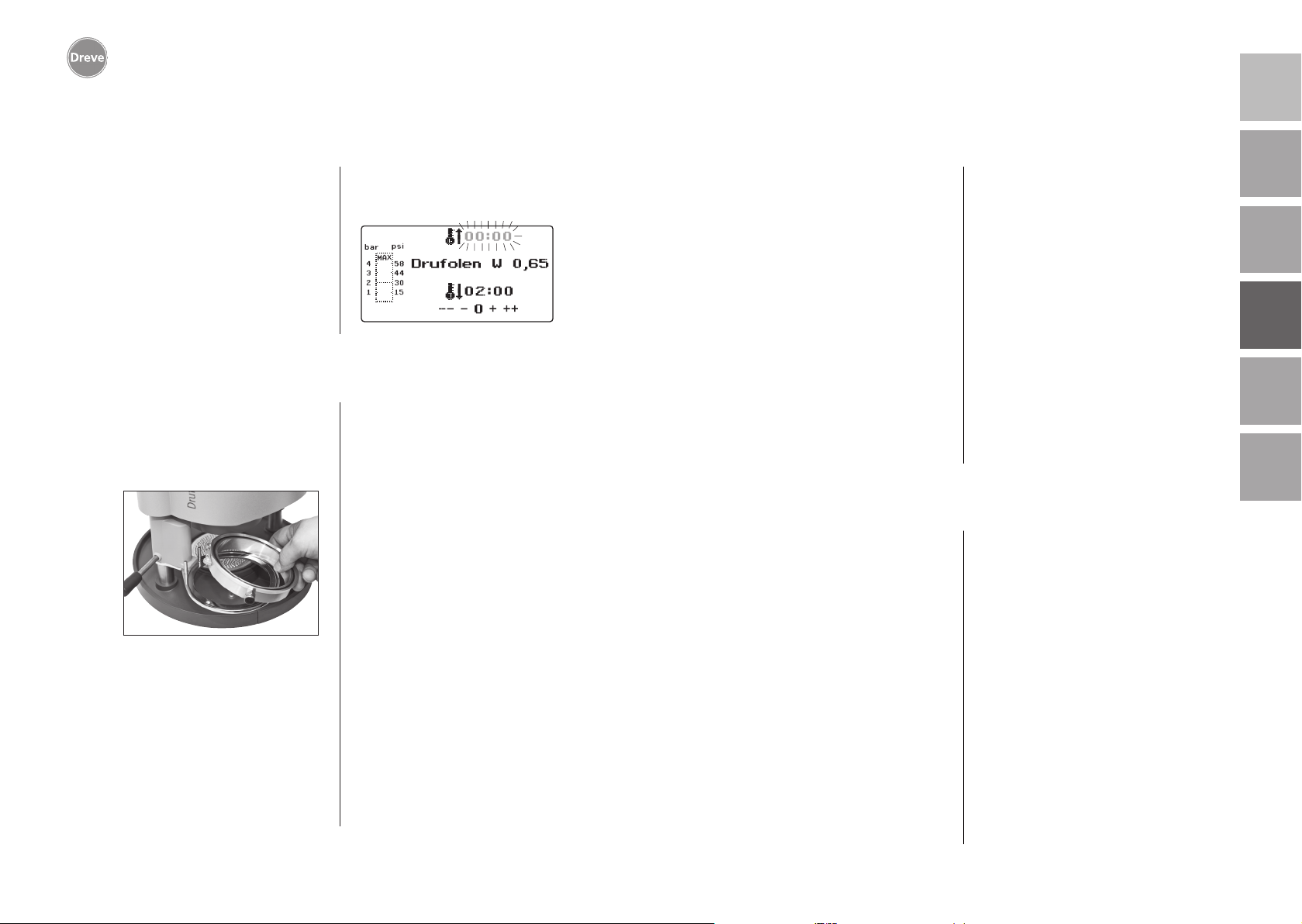
Drufosmart scan
8.2 Ajuste de la presión
deutschenglishfrançaisespañolitaliano
¡La presión de entrada del compresor
no debe superar los 10 bar! En caso
necesario instale una válvula de reducción en la alimentación o reduzca en
general la presión total del compresor.
La presión de servicio del Drufosmart
scan es de 4 bar (58 psi). Se controla y
supervisa digitalmente de forma constante. La presión real en la cámara de
8.3 Inicio del programa
Para iniciar el programa seleccionado,
coloque una lámina correspondiente
al código de barras o la programación
sobre el plato giratorio (11) y fíjela con
ayuda del anillo tensor (13).
El modelo se puede fijar bien sobre la
placa moteada (6) o bien, extrayendo
la placa moteada, mediante granulado directamente en la pieza de inserción (6a).
Información
Para conseguir una adaptación
óptima de la lámina al modelo,
fije el modelo siempre con los
dientes frontales hacia el centro
presión durante el proceso de emputición puede verse en el diagrama de
columnas (g) de la pantalla.
de la lámina. Si se utilizan láminas de termoadaptación duras, se
recomienda embutirlas en granulado. Los modelos que se fijan
sobre la placa moteada no deberían sobrepasar una altura máxima
de 23 mm.
Gire el plato giratorio con el mando
(10) hasta que quede enclavado mecánicamente en el centro por debajo del
equipo. Gire el calefactor (4) con el
mando (5) igualmente hasta que quede
enclavado mecánicamente en el centro
del equipo. Cierre la válvula de salida
de aire del anillo tensor (12).
Pulse la tecla de OK (f). Como confirmación de la activación de la calefacción suena una señal acústica, la unidad
de escáner se apaga y en la pantalla
empieza a transcurrir el tiempo de
calentamiento previamente ajustado.
Información
Por motivos de seguridad, el calefactor está equipado con un interruptor de fin de carrera y, una vez
iniciado un programa, únicamente
funciona cuando está girado hacia
dentro.
Si durante la fase de calentamiento activo se gira el calefactor
de cuarzo hacia fuera, el proceso
de calentamiento se interrumpe
automáticamente. La indicación
de la pantalla (a) se detiene, mostrando el valor restante. Al volver
a girarse el calefactor de cuarzo
hacia dentro, el programa se reactiva.
8.4 Termoadaptación
Tras finalizar el tiempo de calentamiento, suena una señal acústica y
el tiempo en la pantalla se queda en
00:00. La calefacción se desconecta
automáticamente. Extraiga completamente el calefactor (4) con la mano
derecha y por la palanca (5) del centro
del aparato.
Con la mano izquierda apriete la
palanca de activación (34) hacia abajo
y hasta el tope. Manteniendo de nuevo
la palanca del calefactor (5) presionada
contra el tope se cierra totalmente la
cámara de presión y se activa automáticamente la aplicación de presión del
émbolo. Como confirmación de la aplicación de presión se emite una señal
acústica.
Atención! La caja extraible del
calefactor puede alcanzar temperaturas elevadas durante el
funcionamiento y por lo tanto no
se debe tocar ni por un instante.
Una vez transcurrido el tiempo
ajustado, la indicación (a) de la
pantalla parpadea, contando el
tiempo transcurrido desde que
finalizó el tiempo de calentamiento. Este proceso se puede
interrumpir iniciando la siguiente
termoadaptación.
nederlands
Información
Por motivos de seguridad, sólo se
activará el aire comprimido en la
cámara cuando ésta ha sido bajada
manualmente del todo. Para proteger de forma fiable a los operarios de posibles lesiones en los
dedos, el aumento de presión sólo
puede tener lugar cuando el aparato se maneja simultáneamente
con las dos manos (seguro de dos
manos). ¡Compruebe siempre que
al cerrar el émbolo no haya ningún
objeto en el área de contacto del
émbolo y en la pieza de inserción!
74
75
Page 39
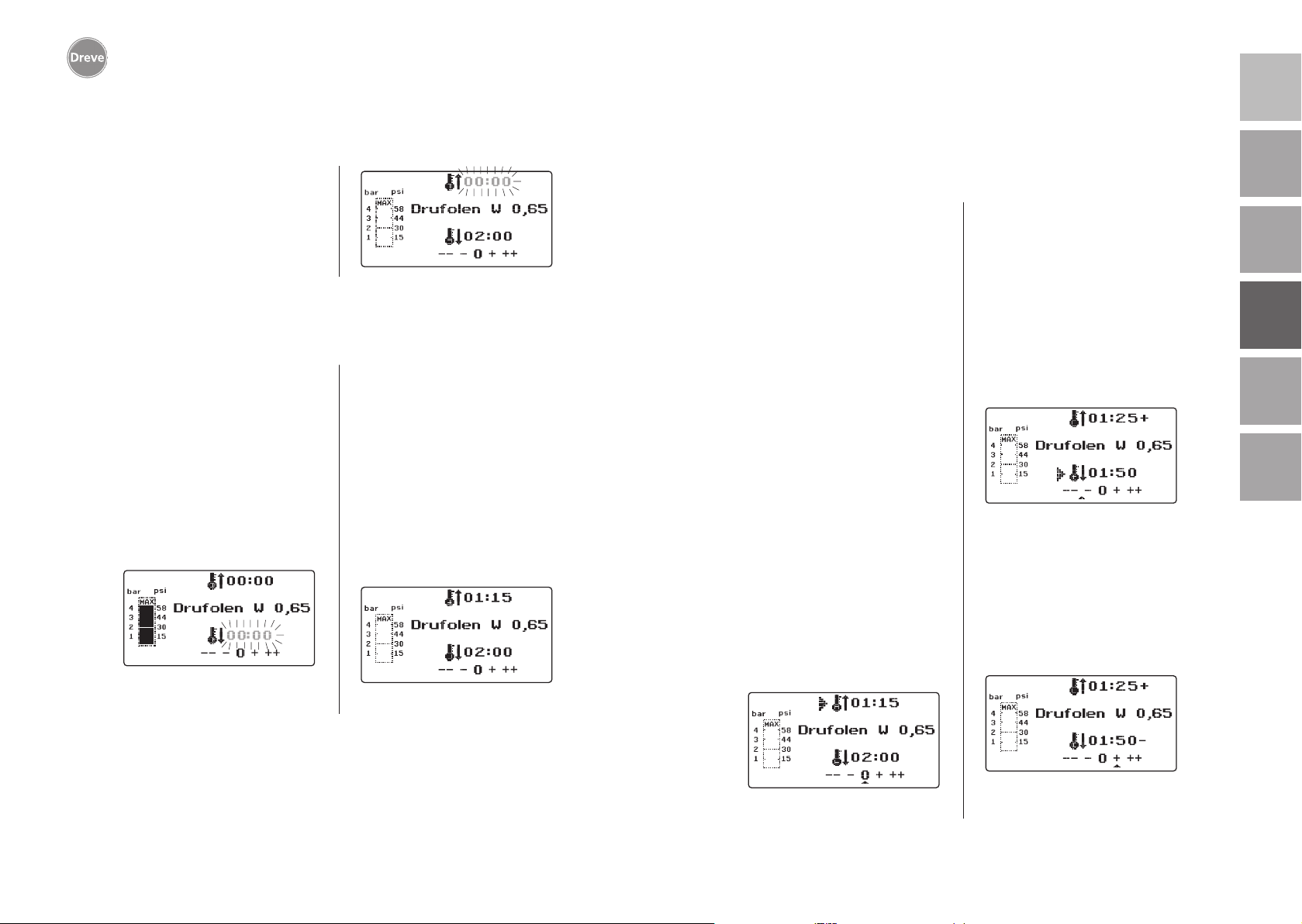
Drufosmart scan
deutschenglishfrançaisespañolitaliano
9. Desviaciones con respecto a la norma general
La presión de 4 bar es generada automáticamente. La presión interior de
la cámara es controlada permanen
temente por la electrónica y, en su
caso, es reajustada. La pantalla indica
el tiempo definido de enfríamiento (c)
que cuenta en dirección inversa hasta
00:00.
-
8.5 Apertura de la cámara de presión
Para conseguir un reenfriamiento completo de la lámina de termoadaptación,
se debe abrir ligeramente la válvula del
anillo tensor (12) al transcurrir dos terceras partes del tiempo de enfriamiento
introducido. De este modo se expulsa el
aire calentado de la cámara de presión
y, debido a la regulación de la presión
de la electrónica, se sustituye por aire
frío. Tras finalizar el tiempo de enfriamiento, suena una señal acústica (la
indicación en la patalla (c) parpadea).
Vuelva a desplazar la palanca del calefactor (5) hasta el tope y manténgala
en esta posición (unos 2–3 s.) hasta
que se elimine toda la presión. A continuación, devuelva la cámara de presión
a su posición de salida retornando a
su posición inicial la palanca de acti
vación (34). Extraiga el plato giratorio
(11) por su mando (10) y extraiga el
anillo tensor y la pieza conformada.
En la pantalla (2) aparece el último programa utilizado, y la unidad de escáner
(1) vuelve a estar lista para un nuevo
proceso de termoadaptación.
9.1 Modificación de los tiempos programados
Los tiempos programados se pueden
prolongar o reducir individualmente en
caso necesario.
Información
La potencia del calentamiento
puede disminuir ligeramente tras
1000 horas de funcionamiento. Se
pueden volver a conseguir resultados de termoadaptación óptimos
alargando los tiempos de calentamiento entre 5 y 10 segundos. Los
tiempos programados en los códi-
-
gos de barras son valores medios
diseñados para uso general. En
zonas de socavación especialmente profunda o modelos muy
altos, la prolongación del tiempo
de calentamiento puede optimizar
los resultados.
Pulsando la tecla del menú (j) tras
escanear los parámetros programados
para el material (véase apartado 8.1), se
puede seleccionar el tiempo de calentamiento (pulsando una vez) o el tiempo
de enfriamiento (pulsando dos veces).
En la pantalla aparece, delante del
tiempo seleccionado, una flecha.
El tiempo de calentamiento se puede
modificar en pasos de cinco segundos,
tanto aumentándolo como reduciéndolo. Para ello, pulse las teclas de menú
(e/i) correspondientes. La desviación
máxima con respecto al tiempo escaneado es de 35 segundos.
La fase de enfriamiento se puede modificar, siguiendo el mismo procedimiento,
en pasos de 10 segundos hasta un
máximo de 70 segundos.
nederlands
Para marcar los parámetros modificados, aparece en la pantalla, detrás de
la indicación, el signo „+“ ó „-“. La
magnitud de la desviación se señala
mediante una escala en el borde inferior de la pantalla.
Los valores modificados se deben confirmar pulsando la tecla de OK (f).
76
Continúe tal como se describe a partir
del apartado 8.2.
77
Page 40
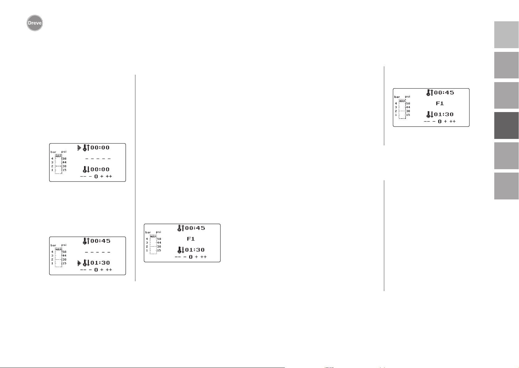
Drufosmart scan
deutschenglishfrançaisespañolitaliano
9.2 Creación y almacenamiento manual de programas
de temporización
Para láminas de termoadaptación que
no disponen del correspondiente código
de barras se pueden introducir y almacenar hasta tres programas de temporización individuales.
Conecte el equipo. Se muestra la pantalla inicial. Pulsando una vez la tecla
de menú (j), en la pantalla aparece en
la posición b – – – – –.
Tal como se describe en el apartado 9.1, pulse la tecla de menú (j)
e introduzca el valor deseado para el
tiempo de calentamiento por medio de
las teclas de menú +/- (e/i). A continuación vuelva a pulsar la tecla de menú
(j) e introduzca la fase de enfriamiento.
Para utilizar estos valores una sola vez,
confirme con la tecla de OK (f). Continue tal como se describe a partir del
apartado 8.2.
Si desea guardar el programa de temporización que ha creado para usarlo más
veces, tiene a su disposición 3 espacios
de almacenamiento (F1–F3).
No confirme con la tecla de OK el programa de temporización que ha creado
(tal como se describe más arriba); en
su lugar vuelva a pulsar la tecla de
menú (j). En la posición b de la pantalla
aparece F1, y se registran los tiempos
introducidos. Para acceder a los espacios F2 y F3 se debe pulsar la tecla de
menú (j) dos o tres veces respectivamente. Para guardar los tiempos en el
espacio de almacenamiento deseado,
pulse la tecla de OK (f).
Continúe tal como se describe a partir
del apartado 8.2.
9.3 Acceso a programas de temporización individuales
Conecte el equipo. Se muestra la pantalla inicial. Pulsando varias veces la
tecla de menú (j), seleccione consecutivamente:
a) el modo de introducción
b) F1
c) F2
d) F3
Con las teclas de menú (d/j) puede
navegar a voluntad entre los puntos
9.4
Plastificación de láminas con tiempo de calentamiento
del programa anteriormente indicados.
Para confirmar el punto del programa
seleccionado, pulse la tecla de OK (f).
Continúe tal como se describe a partir
del apartado 8.2.
desconocido
Cree un programa de temporización
individual con tiempos de calentamiento y enfriamiento elevados (véase
apartado 9.2). Inicie el programa (véase
apartado 8.2). Puede comprobar el
grado de plastificación de la lámina
tocándola con un instrumento de metal
sin punta (p. ej. un aplicador de cera).
Información
La deformabilidad completa de
la lámina sólo se puede comprobar en el borde, pues aquí el calor
fluye hacia el exterior por el contacto con el metal, por lo que es la
zona donde más tarde se alcanza
la flexibilidad necesaria.
Una vez alcanzada la flexibilidad necesaria, inicie el proceso de termoadaptación (véase apartado 8.4). El tiempo
restante de calentamiento se borra de
la pantalla (a) y se muestra el tiempo de
enfriamiento ajustado contando hacia
atrás (c).
La fase de enfriamiento puede interrumpirse en cualquier momento por extracción de la palanca del calefactor (5).
nederlands
78
79
Page 41
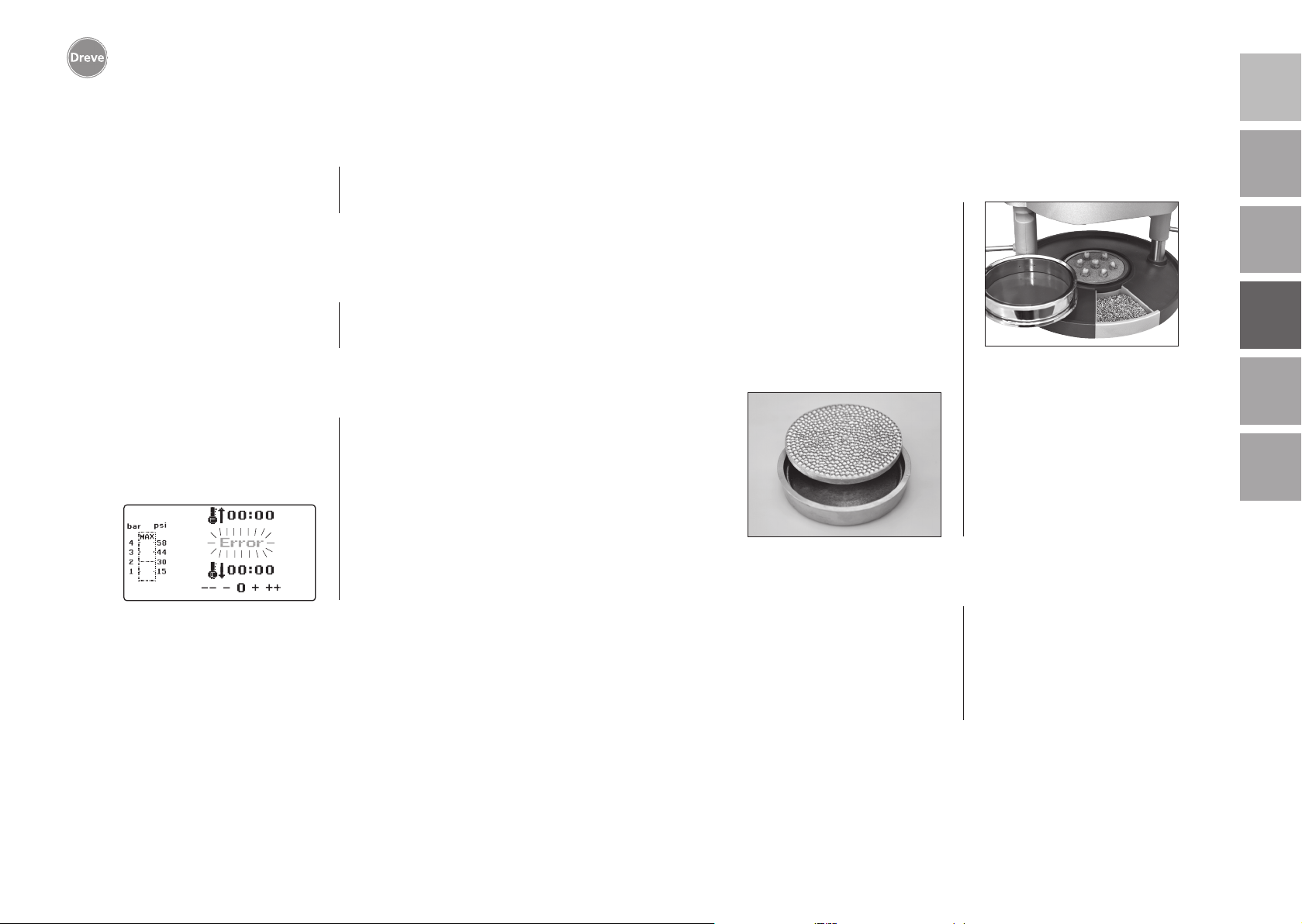
Drufosmart scan
deutschenglishfrançaisespañolitaliano
9.5 Interrupción / finalización de programas
Durante un programa de temporización
en curso, el teclado queda desactivado.
Todas las acciones pueden ser inter-
rumpidas o finalizadas presionando
la palanca de calefacción (5) contra el
tope (durante unos 3 s.).
9.6 Exceso de los tiempos de calentamiento/enfriamiento
introducidos
Una vez trascurrido el tiempo regularmente ajustado (posición a/c en la pantalla) suena una señal acústica. Como
mecanismo de control la duración del
tiempo sobrepasado parpadea en la
pantalla.
9.7 Introducción de un código de barras incorrecto
Si se ecanea un código de barras que
no corresponda a la programación del
Drufomat scan suenan 4 cortas señales
acústicas y en la pantalla aparece en la
posición b la palabra ERROR.
Por escanear de nuevo el código
correcto de barras se puede continuar
como descrito a partir de apartado 8.0.
10 Funciones adicionales opcionales
10.1 Preparación de piezas de molde de fundición
Con la pieza de inserción K-7 se pueden
termoadaptar hasta 7 bases de material sintético al mismo tiempo para la
técnica de coronas y puentes. Fije los
diferentes troqueles por medio de un
material desbloqueante flexible (p.ej.
Fillin) en las escotaduras de la pieza
de inserción K-7 previstas a tal efecto.
Extraiga la placa moteada de la pieza
de inserción y sustitúyala por la pieza
de inserción K-7.
Todos los demás pasos se realizan como
se describe a partir del punto 7.1.
11. Cuidados y mantenimiento
nederlands
80
Desconectar el enchufe de red antes de
efectuar trabajos de cuidado y mantenimiento.
Se recomienda realizar la limpieza en
seco con un paño suave y, si fuera necesario, con una esponja algo humede
cida y un detergente suave. Evite que
entre agua y detergente al interior del
aparato.
Las juntas tóricas deben engrasarse
regularmente con grasa de silicona.
-
81
Page 42
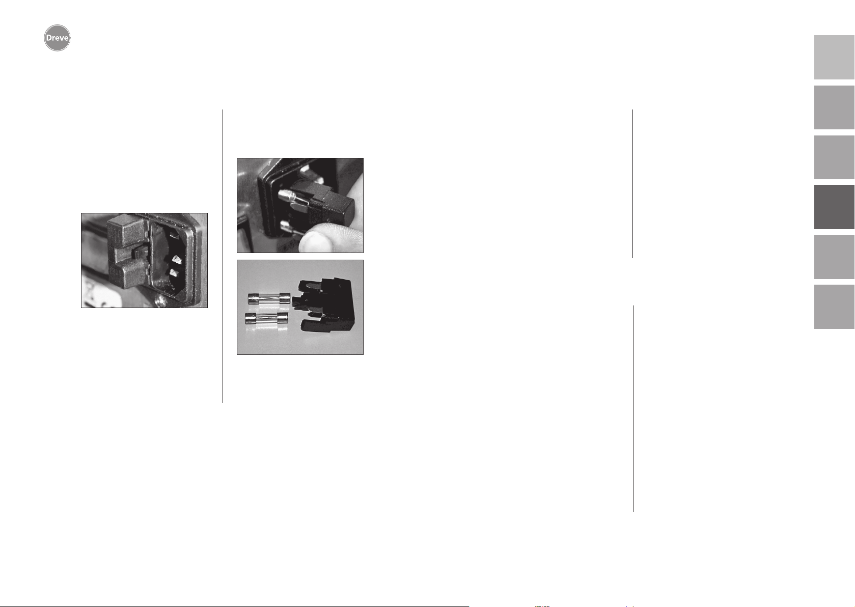
Drufosmart scan
deutschenglishfrançaisespañolitaliano
12. Sustitución de los fusibles
Desenchufe el cable de electricidad de
la red. El soporte de fusibles se encuentra en la parte posterior, integrado en
la conexión a la red eléctrica.
Para comprobar o cambiar los fusibles, apriete hacia dentro la lengüeta
del soporte, manténgala apretada y
extraiga el soporte del fusible.
Extraiga el fusible defectuoso, que está
insertado a presión en el soporte, y sustitúyalo por otro con características equivalentes.
Atención: Utilice únicamente fusibles de la intensidad indicada en
la parte trasera del equipo.
Una vez cambiado el fusible, inserte de
nuevo el soporte en la carcasa hasta
notar que engarza correctamente en
su lugar.
13. Advertencias generales
Los trabajos de reparación y mantenimiento de los aparatos Drufosmart scan
deben ser llevados a cabo únicamente
por personal técnico, y en cualquier
caso interrumpiendo el suministro de
corriente. El grupo de empresas Dreve
sólo responde de la seguridad, fiabilidad y prestaciones del aparato a con
dición de que:
· éste sea utilizado exclusivamente para
su uso previsto.
· sólo lo maneje personal debidamente
formado.
-
14. Garantía
El tiempo de garantía es de 2 años a
partir de la fecha de entrega. Las prestaciones por garantía se aplican solamente por fallos del material o de fabricación. Los derechos de reclamación
por garantía no incluyen el desgaste
natural, ni tampoco los daños que sean
consecuencia de una cesión de riesgo
debido a un uso erróneo o inadecuado,
solicitación excesiva, medios de servicio inadecuados o influencias quimicas, electroquímicas o eléctricas que
no sean contempladas en el contrato.
Toda modificación, reparación o labor
de mantenimiento indebidamente realizada por el comprador o por terceros,
así como posibles desperfectos en los
precintos, anulará la validez de la presente garantía.
· el aparato se use de acuerdo con lo
detallado en estas instrucciones.
· las ampliaciones, nuevas instalaciones,
modificaciones y reparaciones sean
efectuadas por personal autorizado
por Dreve.
Debido a que no cesamos de trabajar
en la mejora de nuestros productos,
nos reservamos el derecho a introducir
modificaciones técnicas sin previo aviso.
Responsabilidad por defectos
Los derechos de reclamación caducan
al transcurrir un año desde la entrega.
No se aceptan derechos de reclamación
por desgaste natural, ni por daños causados por el uso incorrecto o indebido,
uso excesivo, materiales inadecuados
e influencias químicas, electroquímicas o eléctricas no previstas en el contrato después de la cesión del riesgo.
Toda modificación, reparación o labor
de mantenimiento indebidamente realizada por el comprador o por terceros, así como posibles desperfectos en
los precintos, anulará la validez de la
presente responsabilidad por defectos.
nederlands
82
83
Page 43
Drufosmart scan
15. Solución de problemas
deutschenglishfrançaisespañolitaliano
Fallo
El equipo no se enciende
Interruptor principal
encendido pero la
electrónica no funciona
No se puede bajar el
émbolo
El émbolo ha bajado,
el aparato no mantiene
la presión
El émbolo no sube
La electronica se puede
ajustar, no se inicia el
calentamiento
Causa
El equipo no está bien
conectado a la red
Interruptor principal
desconectado
Fusible para baja
intensidad defectuoso
Electrónica defectuosa
No se ha extraído el
calefactor
Electrónica defectuosa
El pulsador no
se ha accionado
correctamente
No se ha descargado la
presión de embuticón
Interruptor de fin de
carrera defectuoso
Válvula magnética
defectuosa o electrónica
defectuosa
El calefactor no está
girado correctamente
hacia dentro
Microinterruptor
defectuoso
Solución
Compruebe la conexión
a la red
Conecte el interruptor
principal
Compruebe el
fusible en caso
necesario, sustitúyalo
La electrónica debe
ser cmprobada por un
especialista
Extraiga el calefactor
El equipo debe ser
comprobado por un
especialista
Mantener accionado
el pulsador durante
3 segundos
Elimine totalmente
la presión de
embutición,consulte
las instrucciones
Pida a un técnico que
sustituya el interruptor
de fin de carrera
El equipo debe ser
comprobado por un
especialista
Gire el calefactor correctamente hacia dentro
Encargue a un especialista que sustituya el
microinterruptor
Fallo
El tiempo de calentamiento transcurre, pero
el equipo no calienta
El tiempo de calentamiento finaliza, pero la
lámina no está suficientemente plastificada
El escáner no se conecta
El equipo no alcanza
la presión previamente
ajustada
El aparato produce
silbidos durante el
proceso deembutición
Causa
Calefactor de cuarzo
defectuoso
Ha saltado el controlador
de temperatura
Se ha excedido el tiempo
de vida del calefactor de
cuarzo
Tiempo de calentamiento
demasiado corto
Tiempo de calefacción
incorrecto
Escáner en pausa
Escáner o electronica
defectouso
Presión de la tubería
demasiado baja
Válvula de ventilación
no cerrada
El anillo tensor no está
correctamente colocado
en el plato giratorio
Fuga en el tubo flexible
de conexióin entre la
válvula y el cilindro
Solución
Sustituya el calefactor
de cuarzo
Sustituya el controlador
de temperatura
Sustituya el calefactor
de cuarzo
Prolongue 5–10 segundos el tiempo de calentamiento
Escanee código de barras
correcto
Pulse brevemente la
tecla OK
Electrónica debe ser comprobada por un especialista, en caso necesario
debe ser sustituida
Aumente la presión
de la tubería
Cierre la vávula de
ventilación
Coloque correctamente
el anillo tensor
Un especialista debe
comprobar el equipo y en
el caso necesario sustituir
el tubo flexible
nederlands
84
85
Page 44
Drufosmart scan
16. Lista de recambios
deutschenglish
No. Denominación
5 Mando calefacción D6505519
6 Pieza de inserción y placa moteada 50591/50592
7 Cajón de granulado 5565
9 Boquilla portatubo, completa D6505536SM
10 Mando plato giratorio D6505519
11 Plato giratorio D6505512
12 Válvula de ventilación 50761
13 Anillo tensor 50038
14 Cristal de cubierta escáner 1429
15 Escáner D6505541X1
17 Carcasa roja D65555RSCAN
Carcasa plateada D65555SSCAN
19 Microinterruptor 55790
20 Carcasa de calentamiento D6505513
21 Calefactor de cuarzo de infrarrojos D6505542
22 Protector contra sobretemperatura 5542
23 Larguero brazo calefactor 55773
24 Fuente de alimentación D6505571
25 Válvula magnética 5202124
26 Cilindro 52019
27 Lámina adhesiva para pantalla 55810
28 Chapa de tope plato giratorio D6555344
29 Soporte plato giratorio D6505514
30 Larguero soporte plato giratorio 55772
31 Placa de base D6505511
33 Conexión a red/soporte de fusibles 51208
34 Palanca de activación D65885
35 Conector palanca/eje D65017
36 Casquillos 55708
37 Interruptor de fin de carrera de palanca de activación E5521
38 Interruptor de tope de calefacción 55790
39 Muelle de recuperación 55861/55862
40 Eje de palanca D6555847
43 Interruptor principal 50841
recambios sin no.
Cable de alimentación para Europa 51021
Cable de alimentación para Inglaterra 51284
Cable de alimentación para América 51283
Electrónica inlc. pantalla, teclado, cable de conexión D6505530
Fusible F3, 15 AT 51321
Aros 112 x 3 mm 51077
Mazo de cables, completo 55520
Chapa de tope calefactor D65016
Tarjeta de control D6505572X1
italiano español français
nederlands
86
87
Page 45
Drufosmart scan
deutschenglishfrançaisespañolitaliano
1. Descrizione dell’apparecchio
Drufosmart scan è una termostampante
multiuso in versione Pressure per l’utilizzo quotidiano in laboratorio odontoiatrico. Lo scanner integrato nella termostampante, grazie al codice a barre
apposto su ciascuna confezione, permette la lettura di informazioni quali
il nome del prodotto, lo spessore della
placca nonché i tempi specifici di riscaldamento e raffreddamento.
La pressione operativa di formatura di
4 bar e il foglio di formatura verticale
consentono di ottenere risultati estremamente precisi.
2. Dati tecnici
Dimensioni (A x L x P): 420 x 320 x 290 mm
Peso: 15 kg
Tensione di rete: 100–240 V/50–60 Hz
Potenza assorbita max.: 115 V–270 W, 230 V–315 W
Fusibile dell‘apparecchio: T 3,15 A
Pressione di funzionamento: 4 bar
Pressione di funzionamento min.: 2 bar
Pressione max. nel condotto: 10 bar
4. Avvertenze di sicurezza
Attenzione! Leggere accuratamente queste avvertenze prima del collegamento e della
messa in funzione dell’apparecchio. E’possibile garantire la sicurezza di funzionamento
e il funzionamento dell’apparecchio solo in caso di rispetto delle prescrizioni generali
di sicurezza e di prevenzione antinfortunistica del legislatore, nonché delle avvertenze
di sicurezza contenute nelle istruzioni per l’uso.
1. L’uso dell’apparecchio è consentito solo in conformità con le presenti
istruzioni per l’uso. Decliniamo qualsiasi responsabilità per danni derivanti
da uso improprio o da errori di manipolazione.
2. Collocare l’apparecchio su una solida
base piana, in grado di sopportare un
peso di esercizio di circa 15 kg.
3. E’opportuno che l’ambiente nel quale
si trova l’apparecchio sia asciutto, per
evitare che possa penetrarvi acqua (ad
es. spruzzi d’acqua).
4. Non conservare sostanze facilmente
infiammabili in prossimità immediata
dell’apparecchio.
5. La tensione indicata sulla targhetta
deve corrispondere a quella della rete
locale.
6. Inserire la spina dell’apparecchio solo
in una presa con terra. Mai toccare la
spina con le mani umide.
8. Prima di ogni utilizzo dell’apparecchio, verificarne la sicurezza di funzionamento e accertarsi che si trovi in
ottimo stato. Qualora lo stato non sia
ineccepibile, non utilizzare l’apparecchio e contrassegnarlo in modo adeguato.
9.
La pressione nel condotto dell’aria
compressa non deve superare i 10 bar.
10. Non introdurre alcun oggetto nell’
apparecchio.
11. Non bloccare i comandi dell’apparecchio.
12. Non bloccare il pistone in discesa.
13. Non mettere le mani sotto il pistone
in discesa.
14. Il corpo girevole del riscaldatore
per irraggiamento raggiunge, durante
il funzionamento, temperature elevate
e per questa ragione evitare di toccarlo,
anche per un istante.
nederlands
88
7.
Utente abilitato: il gestore della macchina deve mettere a disposizione dell’utente le istruzioni per l’uso accertandosi
che questi le legga e le capisca, altrimenti sarà vietato all’utente l’utilizzo
dell’apparecchio.
15. Staccare l’apparecchio dalla rete
elettrica quando non in uso.
16. Targhette ed adesivi devono essere
sempre leggibili; è proibito rimuoverli.
89
Page 46
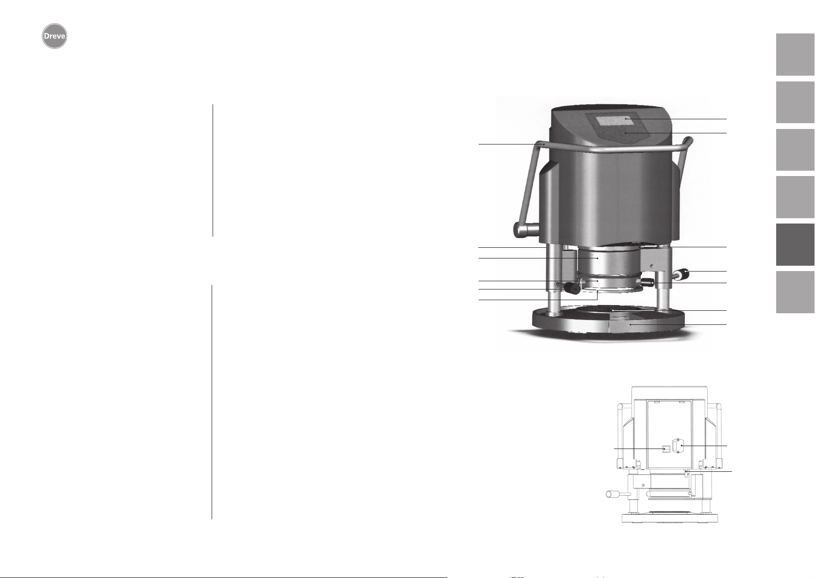
Drufosmart scan
deutschenglishfrançaisespañolitaliano
6. Elementi funzionali
17. Prima di pulire e effettuare manu-
tenzione all’apparecchio, o sostituire
parti, staccare sempre la spina dalla
presa di corrente.
18. Solo personale autorizzato può
aprire e riparare l’apparecchio.
19. Utilizzare solo accessori e parti di
ricambio autorizzati dal costruttore.
Decliniamo qualsiasi responsabilità
per danni derivanti dall’uso di parti
non originali.
5. Messa in funzione
Prima della messa in funzione, assicurarsi che la tensione indicata sulla targhetta corrisponda a quella della rete
locale.
Collegare l’apparecchio a un compressore pneumatico. Inserire il tubetto per
pressione (compreso nella fornitura)
nel connettore dell´ aria compressa (9)
superando una leggera resistenza. Il
tubo viene quindi fissato automaticamente. Per togliere il tubetto per pressione spingere l´anello blu dell´attacco
rapido verso l´alto e rimuovere il tubetto
in basso.
La pressione nel condotto non
deve superare i 10 bar.
Collegare il cavo di alimentazione alla
presa sull’apparecchio (33); inserire la
spina Euro/USA nella presa di corrente.
20. Sono vietate, per ragioni di sicurezza, le trasformazioni e le modifiche.
21. Rispettare imperativamente le
condizioni di utilizzo e manutenzione
contenute nelle presenti istruzioni per
l’uso. L’uso di Drufosmart scan esige
anche l’osservanza delle norme per la
prevenzione degli infortuni sul lavoro
in generale.
Importante: Prima della prima messa
in funzione è indispensabile leggere
attentamente le istruzioni per l’uso. Se
si ha l’impressione di non capire qualcosa, contattare immediatamente il proprio rivenditore o direttamente l’azienda
Dreve Dentamid GmbH.
La fornitura comprende:
1 Drufosmart scan
1 cassetto granulato
1 vaschetta di inserto e disco nodoso
1 anello di tensione con valvola di
scarico
1 confezione base di fogli
1 cavo di alimentazione
1 tubo dell’aria compressa, includente
morsetti per tubi e attacco rapido
1 istruzioni per l’uso in 6 lingue
34
9
4
13
10
11
No.
Nome
1 Scanner
2 Display
3 Tastiera
4 Elemento riscaldante
5 Manopola del riscaldamento
6
Vaschetta di inserto e disco nodoso
7 Cassetto granulato
9 Presa d’aria
10
Manopola del piatto portaplacca
11 Piatto portaplacca
12 Valvola di sfiato
13 Anello di tensione
33 Presa di rete/portafusibili
34 Leva di comando
43 Interruttore principale
43
2
3
1
5
12
6
7
33
nederlands
9
90
91
Page 47
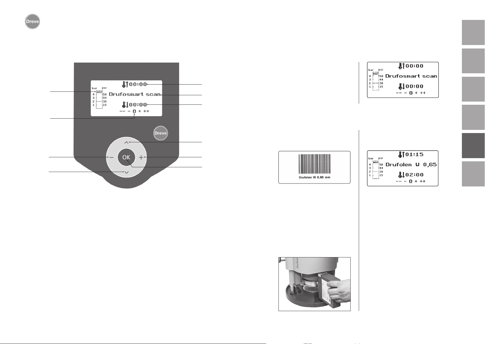
Drufosmart scan
7. Display 8. Comando
Accendere l’interruttore principale (43)
posto sul retro dell’apparecchio; lo
scanner (1) e il display (2) situati sul
a
g
b
c
davanti si attivano. Un segnale acustico
indica che l’apparecchio è operativo. Sul
display appare il nome dell’apparecchio
Drufosmart scan.
deutschenglishfrançaisespañolitaliano
h
i
j
No. Descrizione
a Indicatore del tempo di riscaldamento
b Indicatore del nome del prodotto e dello spessore del materiale
c Indicatore del tempo di raffreddamento
d Sfogliare il menu (indietro)
e Modifica di tempi e pressione (aumento)
f Tasto di validazione/tasto di avviamento del riscaldamento
g Indicatore della pressione interna del pistone
h Indicatore di controllo delle modifiche specifiche dei tempi
i Modifica di tempi e pressione (abbassamento)
j Sfogliare il menu (avanti)
8.1 Modalità di scan
Un’etichetta con codice a barre si trova
d
e
f
su ciascuna confezione esterna con fogli
di termostampaggio Dreve.
Il codice a barre contiene, in forma
cifrata, informazioni quali il nome del
prodotto, lo spessore del materiale nonché i tempi specifici di riscaldamento e
raffreddamento.
Per scansire i dati del materiale con
Drufosmart scan, il codice a barre deve
essere posizionato il più possibile al centro e diritto sull’area di scansione (1).
Un segnale acustico conferma l’avve
nuta registrazione dei dati, e sul display
appaiono tutti i dati necessari.
Info
La luce emessa dallo scanner è
innocua. Anche in caso di diretto
contatto visivo con questa luce
non c’è nulla da temere!
Lo scanner si spegne automaticamente dopo 15 minuti di inattività. Basta premere il tasto OK
dell’apparecchio per riattivarlo.
Lo scanner è disattivato quando
è in corso il processo di termostampaggio. Una volta terminato
il processo, lo scanner si riattiva
automaticamente.
-
nederlands
92
93
Page 48
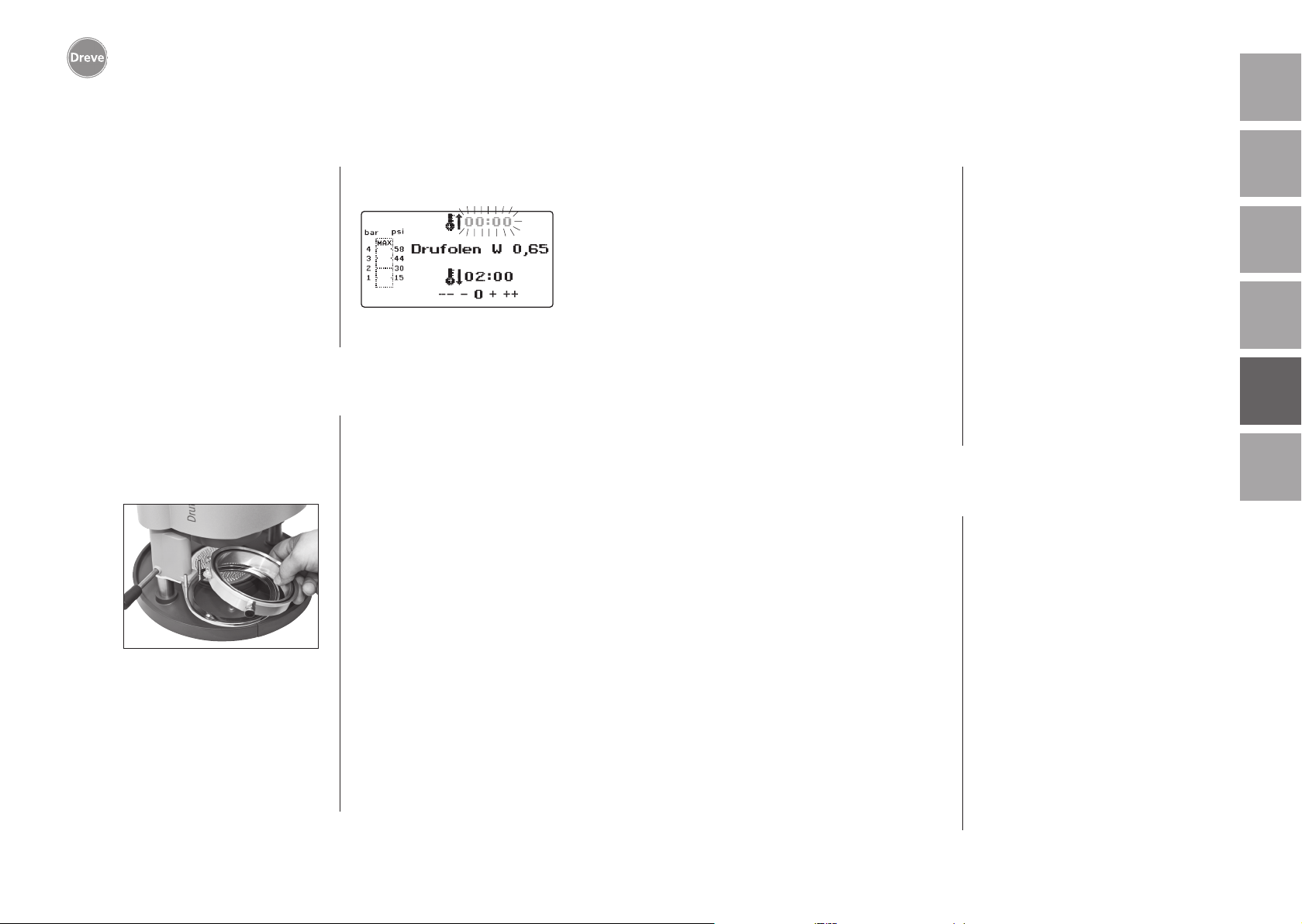
Drufosmart scan
8.2 Impostazione della pressione
deutschenglishfrançaisespañolitaliano
La pressione nel condotto dell’aria
compressa non deve superare i 10 bar!
Eventualmente montare una valvola di
riduzione nel condotto oppure abbassare la pressione del compressore.
La pressione di lavoro della Drufosmart
scan è di 4 bar (58 ps e viene continuamente comandato e controllato digitalmente. Il diagramma a barre (g) sul
display permette il controllo della pres-
8.3 Avvio del programma
Per avviare il programma selezionato,
porre sul piatto portaplacca (11) un
foglio in funzione del codice a barre o
del programma, quindi fissare il foglio
con l’anello di tensione (13).
Il modello è fissato, a scelta, o sul disco
nodoso (6) o, estraendo il disco nodoso,
direttamente nella vaschetta dell’inserto
(6a) per mezzo del granulato.
Info
Al fine di realizzare un adattamento ottimale del foglio al
modello, fissare i modelli con i
sione effettiva nella camera di pressione
durante il processo di termostampaggio.
denti frontali rivolti sempre verso
il centro del foglio. Quando si
usano fogli di termostampaggio
duri, si consiglia il collocamento in
granulato. L’altezza massima dei
modelli da fissare sul disco nodoso
non deve superare i 23 mm.
Girare il piatto portaplacca tramite l’impugnatura (10) fino all’arresto meccanico situato al centro sotto l’apparecchio. Girare anche il riscaldatore per
irraggiamento (4) tramite l’impugnatura (5) fino all’arresto situato al centro
sotto l’apparecchio. Chiudere le valvole
di sfiato dell’anello di tensione (12).
Premere il tasto OK (f). A conferma
dell’attivazione del riscaldamento un
segnale acustico è udibile, l’unità di
scansione si spegne e il display mostra il
countdown del tempo di riscaldamento
preimpostato.
Info
per ragioni di sicurezza, il radiatore al quarzo è dotato di finecorsa e funziona unicamente se
girato in dentro dopo avvio di un
programma.
Nel caso in cui il radiatore al
quarzo sia girato in fuori durante
la fase attiva di riscaldamento, il
processo di riscaldamento si interrompe automaticamente. L’indicatore sul display (a) si ferma allora
sul valore restante. Una volta il
radiatore al quarzo nuovamente
girato in dentro, il programma si
riattiva.
8.4 Termostampaggio
Un segnale acustico è udibile allo spirare del tempo di riscaldamento. L’indicatore del tempo di riscaldamento
indica sul display 00:00. Il riscaldamento si spenge automaticamente.
Svitate completamente il riscaldamento
(4) con la mano destra sull’asta del pulsante (5) dal centro dell’apparecchio.
Con la mano sinistra spingere quindi
verso il basso la leva di attivazione (34),
fino all’arresto. Tirando nuovamente l’asta del pulsante del riscaldamento (5)
fino all’arresto, la camera di pressione
si chiude completamente e forma automaticamente la pressione interna del
pistone. Un segnale acustico risuona a
conferma dell’immissione di pressione.
Attenzione! Il corpo girevole del
riscaldatore per irraggiamento
raggiunge temperature elevate
e per questa ragione evitare di
toccarlo, anche per un istante.
Allo spirare del tempo impostato,
l’indicatore (a) sul display lampeggia e conta il tempo dal momento
in cui è spirato il tempo di riscaldamento. Questo processo può
essere interrotto con l’avvio del
termostampaggio descritto qui
appresso.
nederlands
Info
Per motivi di sicurezza, la pressione nella camera di pressione
può essere attivata solo se questa
è già stata manualmente abbassata del tutto. Per proteggere
in modo affidabile il personale
dallo schiacciamento delle dita,
la formazione di pressione avviene
solo se l’apparecchio viene utilizzato contemporaneamente con
entrambe le mani (dispositivo
di controllo a due mani). Assicurarsi sempre che alla chiusura del
pistone non vi siano oggetti nello
spazio di contatto tra il pistone e
la vaschetta dell’inserto!
94
95
Page 49
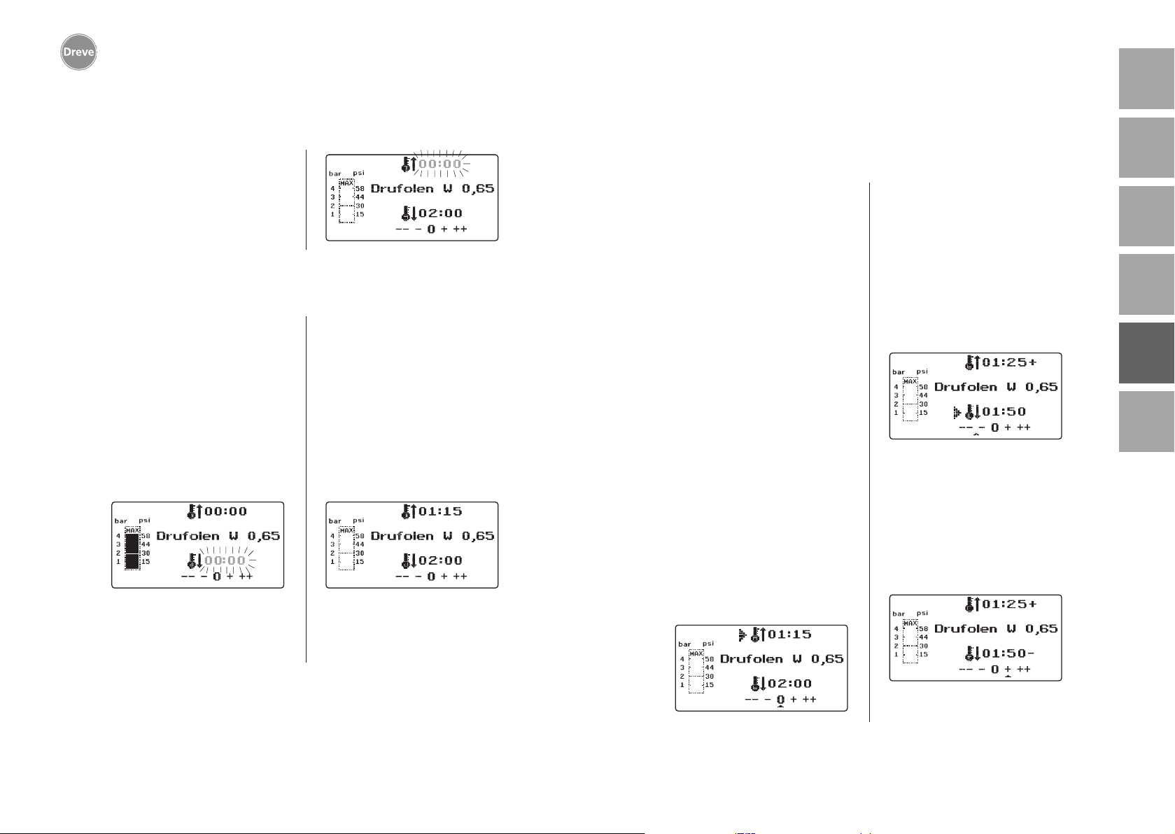
Drufosmart scan
deutschenglishfrançaisespañolitaliano
9. Eccezioni alla regola
La pressione raggiunge automaticamente 4 bar. L’elettronica controlla la
pressione impostata e, qualora necessario, la aggiusta. L’indicatore sul display
indica il tempo di raffreddamento (c)
previsto e conta alla rovescia fino al
raggiungimento di 00:00.
8.5 Apertura della camera di pressione
Per il raffreddamento completo del
foglio di termostampaggio, aprire leggermente la valvola agendo sull’anello
elastico (12) una volta trascorsi 2/3 del
tempo di raffreddamento definito. Ne
consegue l’espulsione dell’aria calda
dal pistone, e la sostituzione della
stessa con aria fredda grazie all’intervento pressostatico dell’elettronica. Un
segnale acustico è udibile allo spirare
del tempo di raffreddamento (l’indicatore sul display (c) lampeggia).
Tirare nuovamente la barra del riscaldamento (5) fino all’arresto e tenerla
in questa posizione finché la pressione
viene rilasciata (ca. 2-3 secondi).
Successivamente, spingendo indietro
la leva di attivazione (34) la camera di
pressione torna nuovamente in posizione iniziale. Spostare in avanti il piatto
portaplacca (11) agendo sulla manopola (10). Estrarre l’anello di tensione e
il risultato del termostampaggio.
Sul display (2) compare l’indicazione del
programma utilizzato per ultimo. L’unità
di scansione (1) è pronta per un nuovo
processo di termostampaggio.
9.1 Modifica dei tempi previsti
E’possibile, all’occorrenza, prolungare
o accorciare i tempi scansiti.
Info
Le prestazioni del riscaldamento
possono calare leggermente dopo
1000 ore di funzionamento. Prolungare i tempi di riscaldamento
(da 5 a 10 sec.) per ottenere nuovamente risultati di termostampaggio ottimali.
I tempi previsti contenuti nel
codice a barre sono valori medi,
adatti per un uso generico. In presenza di zone particolarmente
marginali (sottosquadri) o qualora
l’altezza dei modelli sia molto elevata, prolungare i tempi di riscaldamento può consentire di ottimizzare i risultati.
Dopo la scansione dei parametri previsti
relativi ai materiali (vedi paragrafo 8.1),
è possibile selezionare il tempo di riscaldamento (1 x) o raffreddamento (2 x)
premendo il tasto di menu (j). Sul
display appare una freccia davanti al
tempo impostato.
Il tempo di riscaldamento può essere
prolungato o accorciato a passi di
5 secondi agendo sul tasto di menu corrispondente (tasti e/i). Lo scarto massimo dal tempo di scansione è pari a
35 secondi.
Procedere analogamente per modificare il tempo di raffreddamento a passi
di 10 secondi. Il range massimo è di
70 secondi.
nederlands
Sul display il parametro modificato
è seguito da un segno + o – che ne
segnala l’avvenuta modifica. L’intensità di variazione è misurata su una
scala visualizzata sul bordo inferiore
del display.
Premere il tasto OK (f) per validare i
valori modificati.
96
Eseguire il resto della procedura come
descritto in 8.2 e sgg.)
97
Page 50
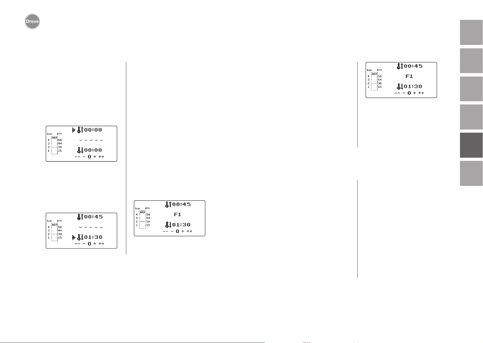
Drufosmart scan
9.2 Creazione e salvataggio manuale di programmi orari 9.3 Richiamo di programmi orari specifici
deutschenglishfrançaisespañolitaliano
E’possibile immettere e salvare massimo tre programmi orari specifici per
fogli di termostampaggio sprovvisti di
codice a barre.
Accendere l’apparecchio. Sul display
compare la schermata iniziale. Premendo una sola volta il tasto di menu
(j) compare sul display in posizione b –
– – – –.
Come descritto al punto 9.1, premere il
tasto di menu (j) e, agendo sui tasti di
menu +/- (e/i), immettere il valore desiderato per il tempo di riscaldamento.
Premere poi nuovamente il tasto di
menu (j) per impostare il tempo di raffreddamento.
Nel caso in cui i due valori immessi
siano destinati ad essere usati una
sola volta, premere il tasto OK (f) per
validarli entrambi. Continuare come
descritto ai punti 8.2 e sgg.
Qualora il programma orario creato sia
destinato ad essere usato più volte, salvarlo in una delle tre locazioni di memoria (F1–F3) disponibili.
Non validare il programma orario creato (vedi sopra) con il tasto OK, ma
premendo di nuovo il tasto di menu (j).
Sul display appare F1 in posizione b, i
tempi immessi sono salvati. Per attivare la locazione di memoria F2 o F3
premere, a seconda della locazione
desiderata, 2 o 3 volte il tasto di menu
(j). Premere poi il tasto OK (f) per salvare i tempi nella locazione di memoria attivata.
Accendere l’apparecchio. Sul display
compare la schermata iniziale. Premere
più volte consecutivamente il tasto di
menu (j) per selezionare:
a) la modalità di immissione
b) F1
c) F2
d) F3
I tasti di menu (d/j) consentono di navigare liberamente fra le opzioni disponibili di cui sopra.Validare l’opzione selezionata agendo sul tasto OK (f).
Continuare come descritto ai punti 8.2
e sgg.
9.4 Plastificazione di fogli con tempo di riscaldamento
non noto
Creare un programma orario specifico
con tempi elevati di riscaldamento e raffreddamento (vedi punto 9.2). Avviare
il programma (vedi punto 8.2). Determinare il grado di plastificazione del
foglio con uno strumento metallico non
aguzzo (ad es. un coltello per cera).
Una volta raggiunta la necessaria flessibilità avviare il processo di termostampaggio (vedi punto 8.4). Il tempo
restante di riscaldamento è cancellato
dal display (a), il tempo di raffreddamento impostato è contato alla rovescia (c).
nederlands
98
Continuare come descritto ai punti 8.2
e sgg.
Info
La malleabilità reale del foglio
può essere determinata unicamente sul bordo, inquanto è proprio sul bordo che il calore defluisce a seguito del contatto con il
metallo. La flessibilità richiesta si
ottiene solo alla fine!
La fase di raffreddamento può essere
interrotta in qualsiasi momento agendo
sul tasto (8).
99
Page 51
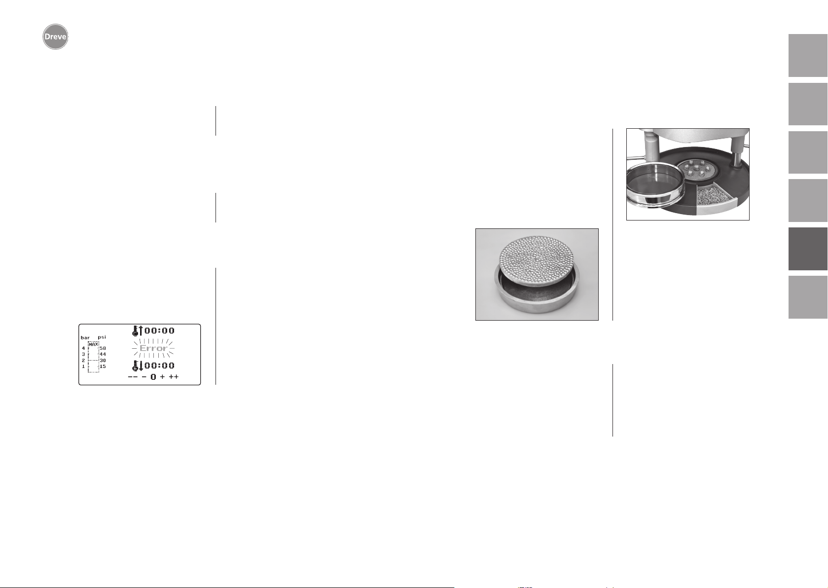
Drufosmart scan
deutschenglishfrançaisespañolitaliano
9.5 Interruzione/fine del programma
Durante lo svolgimento di un programma a tempo, la tastiera è disattivata. L’interruzione/la fine di tutte
le attività può avvenire sollevando la
leva del riscaldamento (5) fino all’arresto (ca. 3 secondi).
9.6 Superamento dei tempi impostati di riscaldamento
e raffreddamento
Un segnale acustico è udibile allo spirare dei tempi regolarmente impostati
(posizioni sul display a/c). Il meccani-
smo di controllo consiste nella visualizzazione lampeggiante sul display del
tempo superato.
9.7 Immissione di un codice a barre errato
In caso di scansione di un codice a barre
non noto a Drufomat scan, sono udibili
quattro brevi segnali d’allarme mentre sul display appare la parola ERROR
(errore) in posizione b.
E’possibile continuare come descritto
ai punti 8.0 e sgg. previa scansione del
codice a barre giusto.
10 Funzioni opzionali
10.1 Produzione di cappette per la tecnica di fusione
L’inserto K-7 permette il termostampaggio simultaneo di massimo 7 basi di
plastica per corone e ponti. Per mezzo
di un materiale sbloccante flessibile
(ad es. Fillin), fissare i singoli punzoni
negli incavi dell’inserto K-7 previsti a
questo scopo. Estrarre il disco nodoso
dalla vaschetta di inserto e sostituire
con inserto K-7.
Eseguire il resto della procedura come
descritto ai punti 7.1 e sgg.
11. Cura e manutenzione
Prima delle operazioni di cura e manutenzione staccare sempre la spina dalla
presa di corrente.
un detergente delicato. Acqua e detergenti non devono penetrare all’interno
dell’apparecchio.
nederlands
100
Pulire, preferibilmente senza bagnare,
con un panno morbido o, al limite, con
una spugna leggermente inumidita con
Periodicamente lubrificare leggermente
gli o-ring con grasso siliconico.
101
Page 52
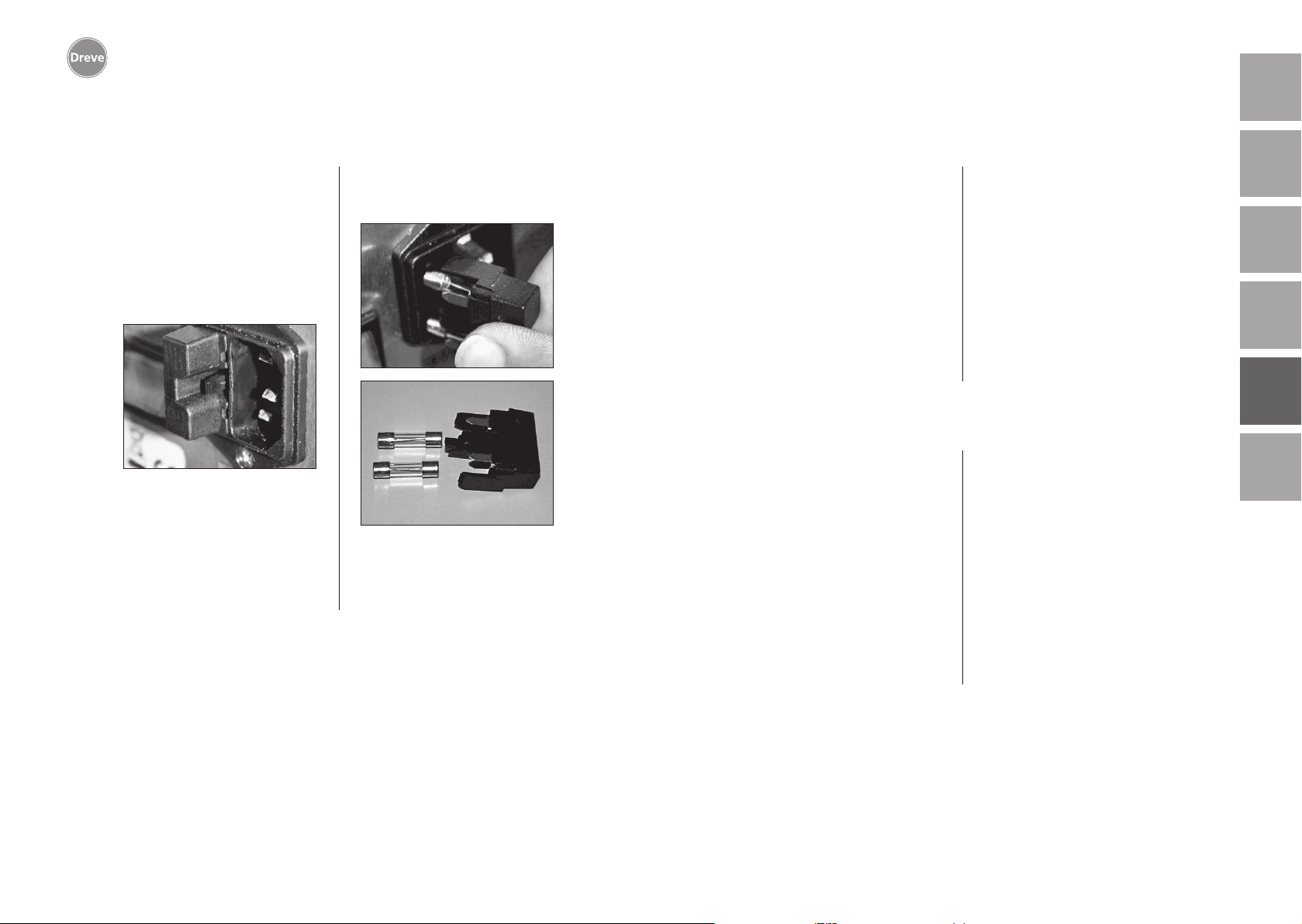
Drufosmart scan
deutschenglishfrançaisespañolitaliano
12. Sostituzione dei fusibili dell’apparecchio
Staccare il cavo di alimentazione elettrica. La sede del fusibile si trova sul
retro dell’apparecchio, integrata nella
presa di corrente.
Per il controllo o la sostituzione dei
fusibili, premere la griglia del portafusibile, tenere premuto ed estrarre il
portafusibile.
Togliere il fusibile dalla sede tirando
leggermente e sostituirlo con un nuovo
fusibile di equivalente amperaggio.
Attenzione: Utilizzare solo fusibili il cui amperaggio corrisponda
alle indicazioni sul retro dell’apparecchio.
Dopo la sostituzione, reinserire il por
tafusibile nel vano esterno, finché il fissaggio scatta in modo evidente.
13. Avvertenze generali
-
Solo specialisti sono abilitati a eseguire
interventi di riparazione su Drufosmart
scan. L’alimentazione di corrente verso
l’apparecchio va in ogni caso interrotta.
L’azienda Dreve è responsabile della
sicurezza, affidabilità e delle prestazioni
dell’apparecchio solo se:
· l’apparecchio viene impiegato solo
conformemente alla sua destinazione.
· l’apparecchio viene messo in funzione
solo da personale specializzato appositamente istruito.
· l’apparecchio viene impiegato con-
formemente alle istruzioni per l’uso.
· aggiunte, nuove impostazioni, modifiche o riparazioni vengono eseguite da
persone autorizzate da Dreve.
Ci riserviamo di apportare modifiche di
carattere tecnico, perché siamo costantemente impegnati nell’evoluzione dei
nostri prodotti.
14. Garanzia
La garanzia ha una durata di 2 anni
dalla data di consegna. La garanzia vale
solo per difetti del materiale o di fabbricazione. Il diritto alla garanzia non
copre l’usura naturale, né i danni causati da uso errato o non conforme a
destinazione, sforzo eccessivo, materiali inadeguati, né influssi di natura
chimica, elettrochimica o elettrica non
contemplati dal contratto. La garanzia
perde validità in caso di modifiche o
operazioni di manutenzione e riparazione eseguiti in modo non idoneo
dall’acquirente o da terzi.
Responsabilità per vizi
Il diritto alla garanzia per vizi cade in
prescrizione dopo 1 anno a partire dalla
consegna. Il diritto alla garanzia per vizi
non copre l’usura naturale, né i danni
causati da uso errato o non conforme
a destinazione, sforzo eccessivo, materiali inadeguati, né influssi di natura chimica, elettrochimica o elettrica non contemplati dal contratto. La garanzia per
vizi perde validità in caso di modifiche
o operazioni di manutenzione e riparazione eseguiti in modo non idoneo
dall’acquirente o da terzi.
nederlands
102
103
Page 53
Drufosmart scan
15. Eliminazione di guasti
deutschenglishfrançaisespañolitaliano
Guasto
L’apparecchio non
funziona
L’interruttore principale
è acceso, l’elettronica
non funziona
Il pistone non scende
Il pistone è sceso,
l’apparecchio non va in
arresto automatico
Il pistone non sale
Causa
Collegamento a rete
non corretto
Interruttore principale
spento
Fusibile per correnti
deboli guasto
Elettronica guasta
Riscaldamento non
è girato in fuori
Elettronica guasta
Tasto azionato in modo
sbagliato
La pressione non si
è consumata
Soluzione
Controllare il
collegamento a rete
Accendere l’interruttore
principale
Controllare ed eventualmente sostituire il fusibile per correnti deboli
L’elettronica va
controllata da un
tecnico specializzato
Girare il riscaldamento
in fuori
L’apparecchio va
controllato da un
tecnico specializzato
Mantenere premuto il
tasto per 3 sec.
Scaricare la pressione
(vedi manuale)
Guasto
Il tempo di riscaldamento è in corso,
ma l’apparecchio non
riscalda
Tempo di riscaldamento
trascorso; il foglio, però,
non è sufficientemente
plastificato
Lo scanner non
si accende
L’apparecchio non
raggiunge la pressione
preimpostata
Causa
Radiatore al
quarzo guasto
Termostato scattato
Durata di vita radiatore
al quarzo superata
Tempo di riscaldamento
troppo breve
Tempo di riscaldamento
errato
Scanner in fase
di riposo
Scanner o elettronica
guasti
Pressione nel condotto
troppo bassa
Soluzione
Sostituire il radiatore
al quarzo
Sostituire il termostato
Sostituire il radiatore
al quarzo
Prolungare il tempo
di riscaldamento di
5–10 sec.
Scansire il codice a
barre corretto
Premere il tasto “OK”
L’elettronica va controllata ed eventualmente
sostituita da un tecnico
specializzato
Aumentare la pressione
nel condotto
nederlands
104
E’possibile impostare
l’elettronica, il riscaldamento non si avvia
Tasto guasto
Elettrovalvola o
elettronica guaste
Riscaldatore per irraggiamento non girato
correttamente in dentro
Microinterruttore guasto
Il tasto va sostituito da
un tecnico specializzato
L’apparecchio va
controllato da un
tecnico specializzato
Girare il riscaldatore
per irraggiamento
correttamente in dentro
Il microinterruttore va
sostituito da un tecnico
specializzato
L’apparecchio emette
un rumore stridente
durante il processo di
termostampaggio
Valvole di sfiato
non chiuse
Anello di tensione
inserito male nella
sede della placca
Il tubetto di collegamento fra la valvola e
il cilindro non tiene
Chiudere le valvole
di sfiato
Posizionare
correttamente l’anello
di tensione
L’apparecchio va
controllato da un
tecnico specializzato,
eventualmente
sostituire il tubetto
105
Page 54
Drufosmart scan
16. Elenco delle parti di ricambio
deutschenglish
No. Nome
5 Manopola del riscaldamento D6505519
6 Vaschetta di inserto e disco nodoso 50591/50592
7 Cassetto granulato 5565
9 Presa d´ aria completa D6505536SM
10 Manopola del piatto portaplacca D6505519
11 Piatto portaplacca D6505512
12 Valvola di sfiato 50761
13 Anello di tensione D50038
14 Copertura in vetro scanner 1429
15 Scanner D6505541X1
17 Corpo rosso D65555RSCAN
Corpo argento D65555SSCAN
19 Microinterruttore 55790
20 Corpo del radiatore D6505513
21 Riscaldatore al quarzo a raggi infrarossi D6505542
22 Termofusibile 5542
23 Asta braccio del radiatore 55773
24 Alimentatore D6505571
25 Elettrovalvola 5202124
26 Cilindro 52019
27 Film adesivo di protezione del display 55810
28 Lamiera di arresto piatto portaplacca D6555344
29 Sostegno piatto portaplacca D6505514
30 Asta piatto portaplacca sostegno 55772
31 Disco di base D6505511
33 Presa di rete/interruttore 51208
34 Leva di comando D65885
35 Leva di abbinamento/asse D65017
36 Boccole di scorrimento 55708
37 Interruttore della leva di comando E5521
38 Interruttore del riscaldamento 55790
39 Molla di ritorno 55861/55862
40 Asse di leva D6555847
43 Interruttore principale 50841
senza codice
Cavo di alimentazione Europa 51021
Cavo di alimentazione Inghilterra 51284
Cavo di alimentazione America 51283
Elettronica includente display, tastiera, cavo di collegamento per scanner
Fusibile F3, 15 AT 51321
O-ring 112 x 3 mm 51077
Gruppo cavetti elettrici completo 55520
Lamiera di arresto riscaldamento D65016
Scheda a controllo (elettronico) D6505572X1
D6505530
italiano español français
nederlands
106
107
Page 55
Drufosmart scan
deutschenglishfrançaisespañolitaliano
1. Beschrijving van het apparaat
De Drufosmart Scan is een universeel te
gebruiken dieptrekapparaat met drukwerking voor het dagelijkse gebruik bij
een tandtechnisch laboratorium. Met de
in het apparaat geïntegreerde scaninrichting is het mogelijk om productnamen, de plaatdikte en de individuele
verwarmings- en afkoeltijden m.b.v. een
op elke verpakkingsunit aangebrachte
barcode rechtstreeks in te lezen.
Een vast ingestelde aanpersdruk van
4 bar zorgt in combinatie met de verticaal vormende folie voor bijzonder
nauwkeurige resultaten.
2. Technische gegevens
B x H x D: 320 x 420 x 290 mm
Gewicht: 15 kg
Netspanning: 100–240 V/50–60 Hz
Max. vermogen: 115 V–270 W, 230 V–315 W
Apparaatzekering: T 3,15 A
Werkdruk: 4 bar
Min. werkdruk: 2 bar
Max. leidingdruk: 10 bar
4. Veiligheidsinstructies
Let op! Deze instructies dienen door de gebruiker vóór het aansluiten en de inge-
bruikname van het apparaat zorgvuldig te worden gelezen. Het veilige gebruik en het
functioneren van het apparaat kunnen alleen worden gewaarborgd als zowel de algemene wettelijke voorschriften voor veiligheid en ongevallenpreventie worden nageleefd
als ook de veiligheidsinstructies uit deze bedieningshandleiding.
1. Het apparaat mag alleen volgens
deze meegeleverde bedieningshandleiding worden gebruikt. Wij aanvaarden geen enkele aansprakelijkheid voor
schade die door ondeskundig gebruik
resp. onjuiste bediening ontstaat.
2. Het apparaat moet op een vlakke
ondergrond worden geplaatst die voor
het bedrijfsgewicht (ca. 15 kg) een toereikende stabiliteit en belastbaarheid
vertoont.
3. Om te voorkomen dat water het
toestel binnendringt (bijv. spatwater),
wordt aangeraden om het toestel in een
drogere omgeving te plaatsen.
4. Bewaar geen licht ontvlambare dingen in de directe omgeving van het
apparaat.
5. De op het typeplaatje vermelde spanning moet overeenkomen met de toe
gevoerde spanning van de stroombron.
6. Het apparaat mag alleen worden
gebruikt bij een stopcontact dat voorzien is van een beschermingsgeleider.
De stroomstekker mag nooit met vochtige handen worden aangeraakt.
7. Gebruikstoestemming voor operators: De exploitant van de machine
-
moet de operator de bedieningshandleiding ter beschikking stellen en nagaan
dat hij/zij deze gelezen en begrepen
heeft. Pas dan mag de operator het
apparaat gaan gebruiken.
8. Het apparaat moet vóór elk gebruik
worden gecontroleerd met betrekking
tot de correcte toestand en de gebruiksveiligheid. Als de toestand van het
apparaat niet helemaal in orde is, mag
het niet worden gebruikt en moet dit
overeenkomstig op het apparaat worden vermeld.
9. De druk van de persluchtleiding mag
niet hoger zijn dan 10 bar.
10. In het apparaat mogen geen voorwerpen worden ingevoerd.
11.
De bedieningselementen van het
apparaat mogen niet worden vastgezet.
12. De neerwaartse beweging van de
zuiger mag niet worden gehinderd.
13. Grijp niet onder de zuiger als deze
naar beneden beweegt.
14. De zwaaibare behuizing van de
straalkachel bereikt tijdens gebruik hoge
temperaturen en mag daarom niet –
ook niet kort – worden aangeraakt.
nederlands
108
109
Page 56
Drufosmart scan
deutschenglishfrançaisespañolitaliano
5. Ingebruikname
15. Het apparaat moet van de stroom
worden afgesloten als het langere tijd
niet wordt gebruikt.
16. Platen en stickers moeten altijd
duidelijk leesbaar zijn en mogen niet
worden verwijderd.
17. Vóór de reiniging en het onderhoud
van het apparaat of het vervangen van
onderdelen moet altijd eerst de stroomstekker eruit worden getrokken.
18. Het apparaat mag uitsluitend door
erkende specialisten worden geopend;
alleen deze specialisten mogen herstelwerkzaamheden uitvoeren.
19. Er mogen alleen reserveonderde
len en accessoires worden gebruikt die
door de producent zijn toegestaan. Bij
schade die door het gebruik van andere
onderdelen ontstaat, vervalt onze aansprakelijkheid.
20. Uit veiligheidsoverwegingen is het
niet toegestaan om zelf wijzigingen of
aanpassingen uit te voeren.
21. De voorgeschreven gebruiks- en
onderhoudsvoorwaarden volgens deze
gebruikshandleiding moeten onder alle
omstandigheden in acht worden genomen. Tijdens de werkzaamheden met
de Drufosmart Scan moeten de algemene voorschriften voor de ongevallenpreventie in acht worden genomen.
-
Vóór de ingebruikname moet worden
gewaarborgd dat de op het typeplaatje
vermelde netspanning overeenkomt
met de toegevoerde spanning van de
stroombron.
Aansluiten van het apparaat op een
persluchtcompressor. Hiervoor de meegeleverde drukslang in de drukslangaansluiting (9) steken, waarbij een
lichte weerstand overwonnen wordt. De
slang zit dan automatisch vast. Om de
drukslang los te maken, de blauwe ring
van de koppeling naar boven drukken
en de slang naar onderen verwijderen.
De druk van de persluchtleiding
mag niet hoger zijn dan 10 bar.
De stroomkabel wordt op het stopcontact (33) aangesloten. Dan wordt
de stroomverbinding met de Euro-/VSstekker tot stand gebracht.
Belangrijk: Voor de eerste ingebruikname moeten alle betrokkenen de
gebruiksinformatie grondig hebben
gelezen. Bij vragen en onduidelijkheden moet – indien nodig – ruggespraak
met het betreffende magazijn of rechtstreeks met Dreve Dentamid GmbH
worden gehouden.
Leveringsomvang
1 Drufosmart Scan
1 schuiflade granulaat
1 inzetschaal en noppenplaat
1 spanring met aftapventiel
1 basisassortiment folies
1 stroomkabel
1 persluchtslang incl. slangklemmen en
snelkoppeling
1 gebruikshandleiding in 6 talen
nederlands
110
111
Page 57
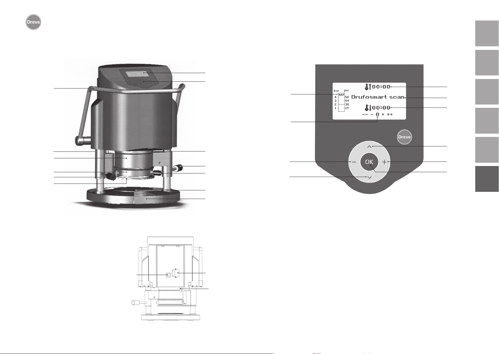
Drufosmart scan
deutschenglishfrançaisespañolitaliano
6. Functiespecifieke elementen
34
9
4
13
10
11
Nr. Benaming
1 Scanner
2 Display
3 Toetsenbord
4 Verwarmingselement
5 Handvat verwarming
6 Noppenplaat en inzetschaal
7 Schuiflade granulaat
9 Persluchtaansluiting
10 Handvat draaischijf
11 Draaischijf
12 Ontluchtingsventiel
13 Spanring
33
Stroomaansluiting/zekeringhouder
24 Activeringshendel
43 Hoofdschakelaar
43
2
3
1
5
12
6
7
33
7. Display
a
g
h
i
j
Nr. Benaming
a Vermelding van verwarmingstijd
b Vermelding productnaam en materiaaldikte
c Vermelding afkoelingstijd
d Menu-items veranderen (naar beneden)
e Wijziging tijdgegevens (naar boven)
f Bevestigings-/startknop verwarming
g Vermelding binnendruk zuiger
h Controledisplay voor individueel gewijzigde tijden
i Wijziging tijdgegevens (naar beneden)
9
j Menu-items veranderen (naar boven)
b
c
d
e
f
nederlands
112
113
Page 58
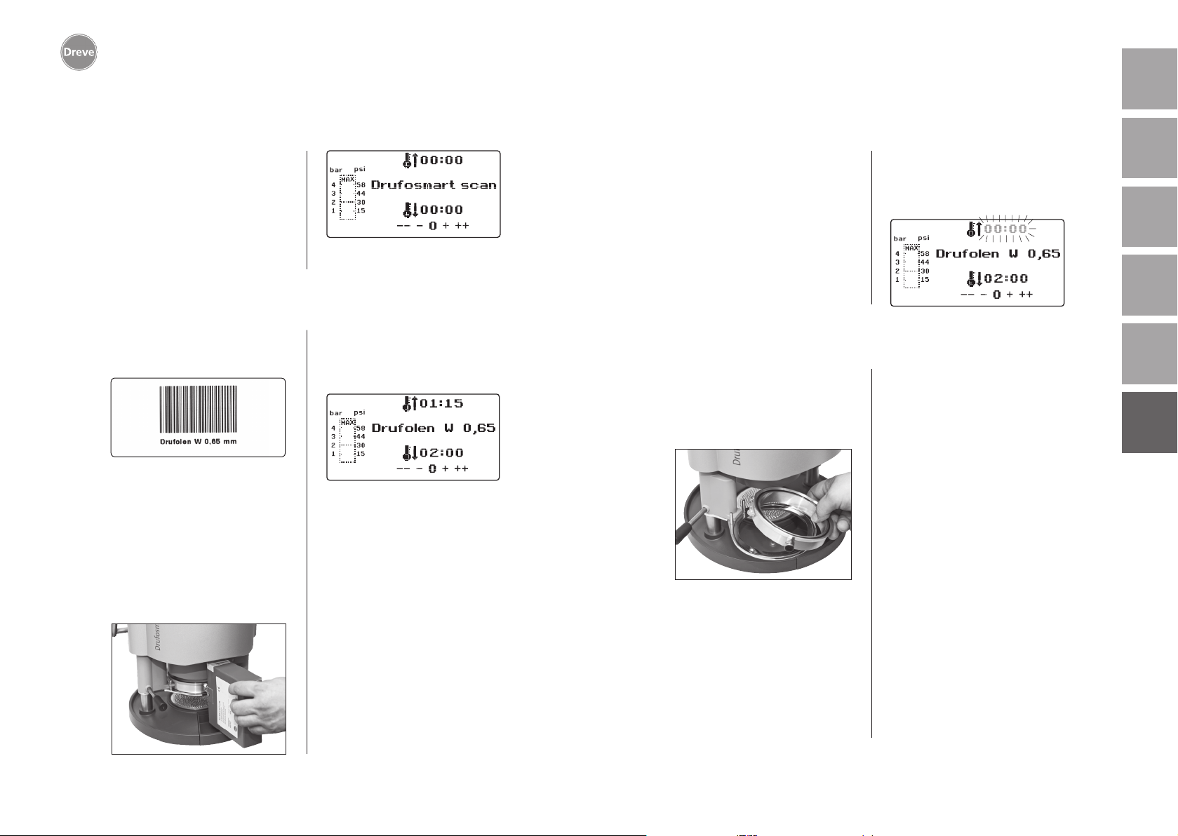
Drufosmart scan
deutschenglishfrançaisespañolitaliano
8. Bediening
Zet de hoofdschakelaar (43) aan de
achterzijde van het apparaat aan. Nu
worden de scanner (1) en de display
(2) aan de voorzijde geactiveerd. Een
akoestisch signaal geeft aan dat het
apparaat klaar is voor gebruik. Op de
display verschijnt het apparaatnaam
Drufosmart Scan.
8.1 Scanmodus
Op elke verpakking van Dreve-dieptrekfolies staat aan de buitenkant een
barcode.
Deze barcode bevat gecodeerd de
productnamen, de materiaaldikte en
de individuele verwarmings- en afkoeltijden.
Om de materiaalgegevens in te lezen bij
de Drufosmart Scan moet de barcode
zo centraal en recht mogelijk onder het
scanveld (1) worden gehouden.
Ter bevestiging voor het inlezen van de
gegevens wordt een signaal gegeven;
op de display verschijnen nu alle benodigde gegevens.
Informatie
Het door de scanner uitgezonden
licht is niet schadelijk en leidt
ook bij direct oogcontact niet tot
schadelijke gevolgen!
De scanner wordt na 15 min. automatisch uitgeschakeld, als deze
niet wordt gebruikt. Door het
indrukken van de Ok-knop wordt
de scanner weer geactiveerd.
Tijdens het actieve dieptrekken
is de scanner gedeactiveerd. Na
het beëindigen van de procedure
schakelt deze zich automatisch
weer in.
8.2 Afstellen van de druk
De binnengaande druk van de compressor mag niet hoger zijn dan 10
bar. Monteer indien nodig een reduceerventiel in de toevoerleiding of
verlaag anders de totale druk van de
compressor.
De werkdruk van de Drufosmart Scan
is 4 bar (58 psi). Deze wordt digitaal
gestuurd en voortdurend gecontroleerd.
8.3 Programmastart
Om het gekozen programma op te starten doet u het volgende: plaats de folie
die overeenkomt met de barcode resp.
de programmering op de draaischijf (11)
en zet deze met de spanring (13) vast.
Het model wordt of op de noppenplaat
(6) of door het verwijderen van de noppenplaat door middel van granulaat in
de inzetschaal (6a) vastgezet.
Informatie
Voor de optimale aanpassing
van de folie op het model zet u
de modellen altijd zo vast dat de
voorste tanden naar het midden
De daadwerkelijke druk in de drukkamer tijdens het dieptrekken wordt
getoond in het staafdiagram (g) op de
display.
van de folie wijzen. Als harde
dieptrekfolies worden gebruikt,
raden we aan om deze in granulaat in te bedden. Modellen die
op de noppenplaat worden vastgezet, mogen niet hoger zijn dan
max. 23 mm.
Beweeg de draaischijf bij het hendel
(10) tot de mechanische stoppositie in
het midden onder het toestel. Beweeg
de straalkachel (4) eveneens bij het
hendel (5) tot de stoppositie in het
midden van het toestel. Sluit het ontluchtingsventiel van de spanring (12).
Druk op de Ok-knop (f). Ter bevestiging
voor het activeren van de verwarming
wordt een akoestisch signaal gegeven,
de scanunit wordt gedoofd en op de
display verstrijkt de vooraf ingestelde
verwarmingstijd.
nederlands
114
115
Page 59
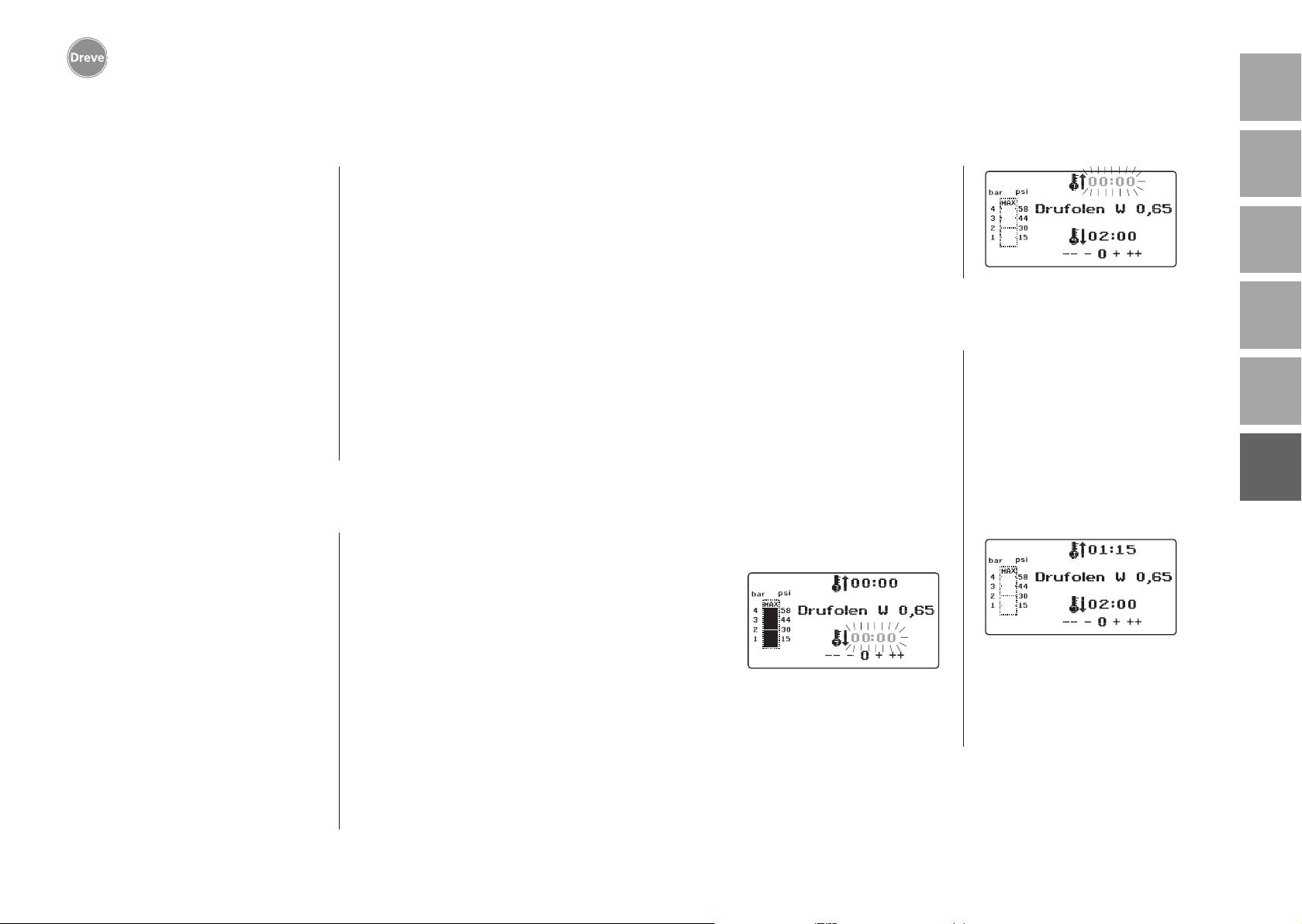
Drufosmart scan
deutschenglishfrançaisespañolitaliano
Informatie
Om veiligheidsredenen is de
kwartsstraler uitgerust met een
eindschakelaar. Deze werkt na het
opstarten van een programma uitsluitend als de schijf naar binnen
is gedraaid.
Als de kwartsstraler tijdens de
actieve verwarmingsfase naar
buiten wordt gedraaid, wordt het
verwarmen automatisch afgebroken. De weergave op de display (a)
stopt en geeft nu de restwaarde
aan. Door het opnieuw naar binnen
draaien van de kwartsstraler wordt
het programma weer geactiveerd.
8.4 Dieptrekken
Na het verstrijken van de opwarmtijd
wordt een akoestisch signaal geactiveerd en de verwarmingstijd op de
display is 0.00. De verwarming wordt
automatisch afgeschakeld. Draai de verwarming (4) met de rechter hand op de
knopstang (5) helemaal uit het midden
van het apparaat.
Druk dan met de linker hand het activeringshendel (34) tot de stoppositie naar
beneden. Als de verwarmings-knopstang (5) nogmaals wordt aangetrokken
tot aan de stoppositie, wordt de drukkamer helemaal gesloten. Dan wordt
binnen de zuiger druk opgebouwd. Ter
bevestiging van deze druktoevoer wordt
een akoestisch signaal geactiveerd.
Let op! De zwaaibare behuizing
van de straalkachel bereikt tijdens gebruik hoge temperaturen en mag daarom niet – ook
niet kort – worden aangeraakt.
Na het verstrijken van de ingestelde tijd knippert de weergave
(a) op de display en wordt de duur
na het verstrijken van de verwarmingstijd geteld. Dit proces kan
worden onderbroken door het
erop volgende dieptrekken.
Informatie
Om veiligheidsredenen kan de
druk in de drukkamer pas worden
geactiveerd als deze al compleet
manueel naar beneden is gebracht.
Om de operators betrouwbaar te
beschermen tegen het inklemmen
van vingers kan alleen dan druk
worden opgebouwd als het toestel gelijktijdig met twee handen
wordt bediend (tweehandenbeveiliging). Let hierbij altijd erop dat
zich bij het sluiten van de zuiger
geen voorwerpen in het contactgebied van zuiger en inzetschaal
mogen bevinden!
De druk wordt automatisch gegenereerd voor 4 bar. De binnendruk in de
kamer wordt door de elektronica continue gecontroleerd en indien nodig aangepast. Op de display wordt de ingestelde afkoelingstijd (c) vermeld en telt
dan terug naar 00:00.
8.5 Openen van de drukkamer
Om de dieptrekfolie helemaal terug af
te kunnen koelen, wordt geadviseerd
om na het verstrijken van twee derde
van de ingestelde afkoelingstijd het
ventiel bij de spanring (12) een beetje
te openen. Hierdoor wordt de opgewarmde lucht uit de drukkamer afgevoerd en dan vanwege de drukregeling van de elektronica door koude lucht
vervangen. Na het verstrijken van de
afkoelingstijd wordt een akoestisch signaal (weergave op de display (c) knippert) geactiveerd.
Trek de knopstang van de verwarming
(5) nog eens tot de stoppositie en houd
deze hier (ca. 2–3 sec.) totdat de druk
wordt gegenereerd.
Beweeg dan de drukkamer weer in de
uitgangspositie door het activeringshendel (34) terug te bewegen. Beweeg de
draaischijf (11) bij het handvat (10) naar
buiten en verwijder de spanring en het
resultaat van het dieptrekken.
Op de display (2) verschijnt het laatst
gebruikte programma. De scanunit (1)
is nu gereed voor het volgende dieptrekproces.
nederlands
116
117
Page 60
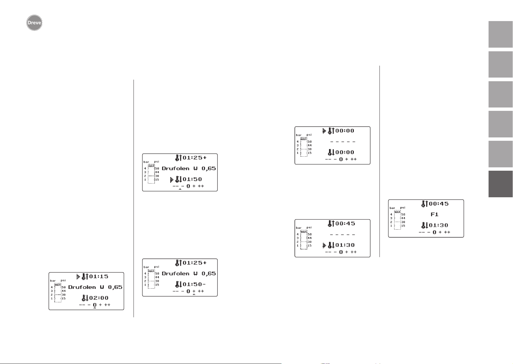
Drufosmart scan
deutschenglishfrançaisespañolitaliano
9. Afwijkingen van de normale situatie
9.1 Wijzigingen van de ingestelde tijden
De gescande tijden kunnen – indien
nodig – individueel korter of langer
worden afgesteld.
Informatie
Het vermogen van de verwarming
kan na 1000 bedrijfsuren lichtelijk achteruitgaan. Door het verlengen van de verwarmingstijden
met 5 tot 10 sec. kunnen dan weer
optimale resultaten bij het dieptrekken worden verkregen.
De d.m.v. de barcode ingestelde
tijden zijn gemiddelde waarden
die voor algemeen gebruik gekozen zijn. Bij bijzonder sterk onder
zich gaande gebieden of zeer hoge
modellen kunnen de resultaten
door het verlengen van de verwarmingstijd worden verbeterd.
Na het scannen van de ingestelde materiaalparameters (zie paragraaf 8.1) kan
door het indrukken van de menuknop
(j) de verwarmingstijd (1 x) of de afkoelingstijd (2 x) worden geselecteerd. Op
de display verschijnt voor de gekozen
tijd een pijl.
De opwarmtijd kan in stappen van
5 seconden in positieve en negatieve
richting worden gewijzigd. Druk hiervoor de menuknoppen (e/i) volgens
de toetsbeschrijving in. De maximale
afwijking bij de scantijd is 35 seconden.
De afkoelingsfase kan met dezelfde
procedure in stappen van 10 seconden met maximaal 70 seconden wor
den gewijzigd.
Ter indicatie van de gewijzigde parameters verschijnt op de display achter
de waarde een + of een -. Hoe sterk de
waarde afwijkt, wordt op een schaal
bij de onderste rand van de display
getoond.
Bevestig de gewijzigde waarden door
op de Ok-knop (f) te drukken.
9.2 Manueel tijdprogramma’s aanmaken en opslaan
Bij dieptrekfolies die niet voorzien zijn
van een betreffende barcode, kunnen
tot drie eigen tijdprogramma’s worden
aangemaakt en opgeslagen.
Schakel het apparaat in. Op de display
verschijnt de startweergave. Druk 1 x op
de menuknop (j). Nu verschijnt – – – – –
bij positie b.
-
Druk zoals bij punt 9.1 beschreven op
de menuknop (j) en voer de gewenste
waarde voor de verwarmingstijd in
m.b.v. de menuknoppen +/- (e/i). Druk
vervolgens nog eens op de menuknop
(j) en voer de betreffende afkoelingsfase in.
Bevestig de ingevoerde waarden voor
eenmalig gebruik met de Ok-knop (f).
Volg verder de uitleg vanaf punt 8.2.
Als het aangemaakte tijdprogramma
voor herhaald gebruik opgeslagen
wordt, heeft u 3 geheugenposities
(F1–F3) ter beschikking.
Bevestig het aangemaakte tijdprogramma (zie boven) niet door op de
Ok-knop te drukken maar druk opnieuw
op de menuknop (j). Op de displaypositie b verschijnt nu F1; de ingevoerde
tijden worden overgenomen. De geheugenposities F2 en F3 worden gebruikt
door 2 x resp. 3 x op de menuknop (j)
te drukken. De tijden bij de gewenste
geheugenpositie worden door het drukken van de Ok-knop (f) opgeslagen.
Volg verder de uitleg vanaf punt 8.2.
nederlands
118
Volg voor de andere acties verder de
uitleg vanaf punt 8.2.
119
Page 61
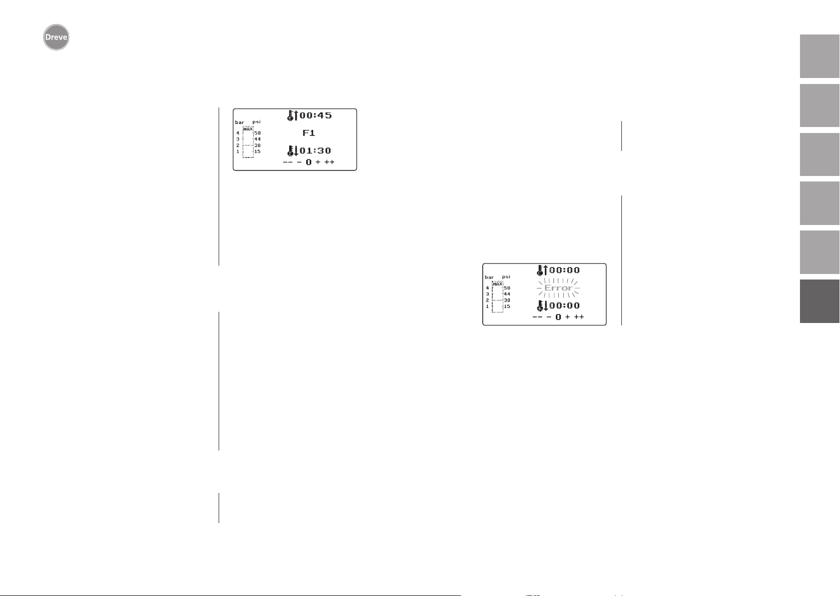
Drufosmart scan
deutschenglishfrançaisespañolitaliano
9.3 Opvragen van individuele tijdprogramma’s
Schakel het apparaat in. Op de display
verschijnt de startweergave. Door meermals te drukken op de menuknop (j)
kiest u achtereenvolgens:
a) de invoermodus
b) F1
c) F2
d) F3
Met de menuknoppen (d/j) kunt u vrij
tussen de bovenstaande programmaonderdelen bewegen. Bevestig het geselecteerde programmaonderdeel met de
Ok-knop (f).
Volg verder de uitleg vanaf punt 8.2.
9.4 Plastificeren van folie met onbekende opwarmtijd
Maak een individueel tijdprogramma
met hoge verwarmings- en afkoelingstijden (zie punt 9.2). Start het programma (zie punt 8.2). De mate van
plastificering bij de folie kunt u met een
stomp metalen voorwerp (bijv. wasmes)
voelen.
Informatie
De totale vervormbaarheid van de
folie kan alleen bij de rand worden
gevoeld omdat de warmte hier
door de metalen contacten weg-
stroomt en de benodigde flexibiliteit het laatst worden bereikt!
Schakel na het bereiken van de benodigde flexibiliteit het dieptrekken in (zie
punt 8.4). De resterende verwarmingstijd wordt op de display (a) verwijderd
en de ingestelde afkoelingsfase wordt
aftellend weergegeven (c).
Het afkoelen kan altijd door het uittrekken van de verwarmings-knopstang (5)
worden afgebroken.
9.6 Overschrijden van de ingestelde verwarmings-/
afkoeltijden
Na het verstrijken van de vast ingestelde tijden (displaypositie a/c) wordt
een akoestisch signaal geactiveerd. Ter
controle wordt de tijd van de overschrij
ding knipperend weergegeven op de
display.
9.7 Invoeren van een foute barcode
Als een barcode wordt gescand die niet
overeenkomt met de programmering
van de Drufosmart Scan, worden vier
korte waarschuwingssignalen geactiveerd. Op de display verschijnt bij positie b het woord ERROR (fout).
Door het opnieuw scannen van de juiste
barcode kunt u de procedure vervolgen
zoals vanaf punt 8.0 beschreven.
-
nederlands
120
9.5 Afbreken/beëindigen van het programma
Tijdens het lopende tijdprogramma
zijn de knoppen gedeactiveerd. Om
alle acties af te breken of te beëindi-
gen moet u de verwarmings-knopstang
(5) tot aan de stoppositie aantrekken
(ca. 3 sec.).
121
Page 62
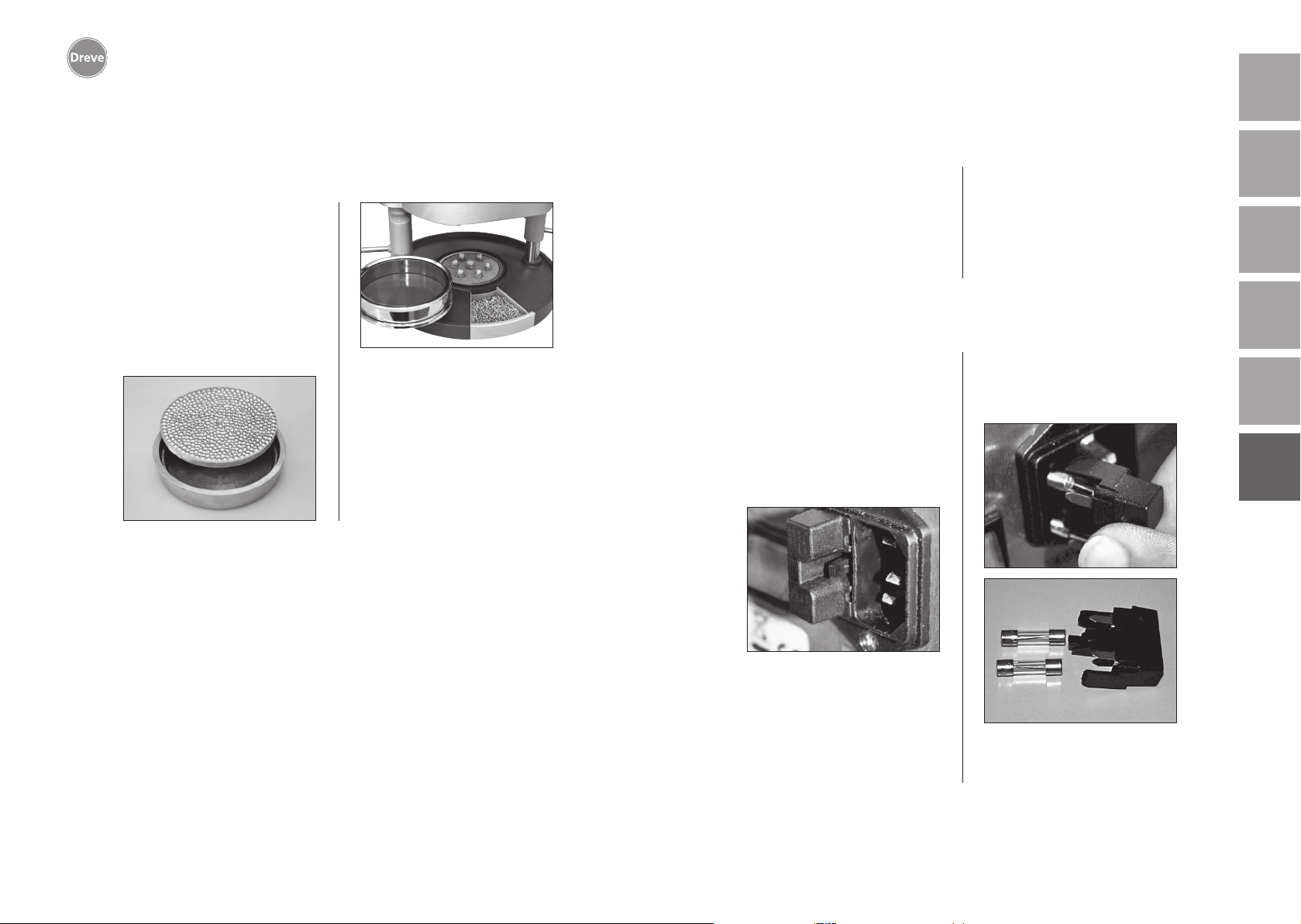
Drufosmart scan
deutschenglishfrançaisespañolitaliano
10 Optionele extra functies
10.1 Vervaardigen van gietvormdelen
Met het K-7 inzetstuk kunnen tot 7
kunststofkappen tegelijkertijd worden
diepgetrokken voor het gebruik bij kronen en bruggen. Bevestig hiervoor de
aparte stompen met een flexibel uitblokmateriaal (bijv. Fillin) in de hiervoor bestemde uitsparingen van het
K-7 inzetstuk. Neem de noppenplaat
uit de inzetschaal en vervang deze door
het K-7 inzetstuk.
Volg voor de andere acties verder de
uitleg vanaf punt 7.1.
11. Reiniging en onderhoud
Vóór reinigings- en onderhoudswerkzaamheden moet altijd de stekker uit
het stopcontact worden getrokken.
Gebruik voor het schoonmaken bij voorkeur een droge, zachte doek, eventueel ook een licht vochtige spons met
een mild reinigingsmiddel. Het water
en het reinigingsmiddel mogen niet in
het apparaat komen.
De O-ringen dienen regelmatig licht met
siliconenvet gesmeerd te worden.
12. Vervangen van de zekeringen bij het apparaat
Onderbreek de stroomtoevoer. De zekeringhouder bevindt zich aan de achterkant van het apparaat en is geïntegreerd bij de stroomaansluiting.
Druk voor het controleren of vervangen
van de zekeringen de drukklem van de
houder in, laat deze ingedrukt en trek
de houder uit het apparaat.
Plaats de zekeringhouder na het vervangen door lichte druk weer in de
behuizing totdat deze duidelijk hoorbaar vastklikt.
nederlands
122
Trek de defecte zekering met een lichte
ruk uit de houder en vervang deze door
een nieuwe gelijkwaardige zekering.
Belangrijk: Gebruik uitsluitend de
op de achterzijde vermelde zekeringsterkte.
123
Page 63
Drufosmart scan
deutschenglishfrançaisespañolitaliano
13. Algemene opmerkingen
Reparatie- en onderhoudswerkzaamheden aan de Drufosmart Scan mogen
uitsluitend door deskundig personeel
worden uitgevoerd. De stroomtoevoer
van het apparaat moet hiervoor in elk
geval worden onderbroken. Het bedrijf
Dreve is alleen in de volgende gevallen
voor de veiligheid, betrouwbaarheid en
de prestaties van het apparaat verantwoordelijk:
· als het apparaat alleen voor de betreffende toepassing wordt gebruikt;
· als de bediening alleen door desbetreffend opgeleid personeel plaatsvindt;
· als het apparaat volgens deze bedieningshandleiding wordt gebruikt;
· als uitbreidingen, wijzigingen, reparaties of een nieuwe afstelling worden
uitgevoerd door personen die door
Dreve bevoegd zijn.
Omdat we voortdurend werken aan de
verdere ontwikkeling van onze producten behouden we ons het recht op technische wijzigingen voor.
14. Garantie
De garantieperiode is 2 jaar vanaf leveringsdatum. De garantie geldt alleen
voor materiaal- en productiefouten.
Deze garantie heeft geen betrekking
tot natuurlijke slijtage, en geldt verder
niet bij schade die na het overgaan van
risico ontstaat ten gevolge van foutief
gebruik of ander gebruik dan dat volgens bestemming, door overmatige
belasting, niet geschikte productiemiddelen en andere chemische, elektrochemische of elektrische invloeden
die volgens het contract niet worden
vermeld. Verder vervalt het recht op
garantie indien door de besteller of derden wijzigingen of instandhoudings- en
onderhoudswerkzaamheden ondeskundig worden uitgevoerd evenals in het
geval van beschadiging van plombes.
Aansprakelijkheid bij gebreken
Alle aanspraken in het geval van gebreken vervallen na het verstrijken van een
jaar na levering. Deze aanspraken bij
gebreken hebben geen betrekking tot
natuurlijke slijtage, en gelden verder
niet bij schade die na het overgaan van
risico ontstaat ten gevolge van foutief
gebruik of ander gebruik dan dat volgens bestemming, door overmatige
belasting, niet geschikte productiemiddelen en andere chemische, elektrochemische of elektrische invloeden
die volgens het contract niet worden
vermeld. Verder vervalt het recht op
garantie indien door de besteller of derden wijzigingen of instandhoudings- en
onderhoudswerkzaamheden ondeskundig worden uitgevoerd evenals in het
geval van beschadiging van plombes.
nederlands
124
125
Page 64
Drufosmart scan
15. Hulp bij het verhelpen van storingen
deutschenglishfrançaisespañolitaliano
Storing
Apparaat geeft geen
functie aan
Hoofdschakelaar licht
op, elektronica geeft
geen functie aan
Zuiger kan niet
naar beneden
worden gebracht
Zuiger is beneden,
Apparaat gaat niet
naar zelfstandig
houdende positie
Zuiger kan niet naar
boven worden gebracht
Oorzaak
Stroomverbinding
niet correct
De hoofdschakelaar
staat uit
Fijnzekering is defect
Elektronica is defect
Verwarming is niet
naar buiten gedraaid
Elektronica is defect
Knop verkeerd bediend
Aanpersdruk is
niet verlaagd
Oplossing
Controleer de
stroomverbinding
Schakel de
hoofdschakelaar in
Controleer de
fijnzekering en vervang
deze indien nodig
De elektronica moet
door een specialist
worden gecontroleerd
Draai de verwarming
naar buiten
Het apparaat moet
door een specialist
worden gecontroleerd
Trek 3 sec. aan de knop
Verlaag de aanpersdruk
zie handleiding
Storing
Verwarmingstijd loopt
niet, Apparaat wordt
echter niet verwarmd
Verwarmingstijd
verstreken, folie
niet voldoende
geplastificeerd
Scanner wordt niet
ingeschakeld
Apparaat bereikt de
ingestelde druk niet
Oorzaak
Kwartsstraler is defect
Temperatuursensor
heeft gereageerd
Bedrijfsduur
kwartsstraler verstreken
Verwarmingstijd te kort
Foute verwarmingstijd
geselecteerd
Scanner in rustfase
Scanner of elektronica
is defect
Leidingdruk te laag
Oplossing
Vervang de
kwartsstraler
Vervang de
temperatuursensor
Vervang de
kwartsstraler
Verleng de
verwarmingstijd
met 5–10 sec.
Scan de juiste barcode
Druk kort op de
Ok-knop
De elektronica moet
door een deskundige
gecontroleerd en
indien nodig worden
vervangen
Verhoog de leidingdruk
nederlands
126
Elektronica kan niet
worden ingesteld,
Verwarming start niet
Eindschakelaar is defect
Magneetventiel of
elektronica is defect
Straalkachel niet goed
naar binnen gedraaid
Microschakelaar
is defect
Laat de eindschakelaar
door een specialist
vervangen
Het apparaat moet door
een specialist worden
gecontroleerd
Draai de straalkachel
goed naar binnen
Laat de microschakelaar
door een specialist
vervangen
Apparaat maakt
sissende geluiden
tijdens het dieptrekken
Ontluchtingsventiel niet
gesloten
Spanring verkeerd
geplaatst in de
plaatopname
Verbindingsslang tussen
ventiel en cilinder
vertoont lekkage
Sluit het
ontluchtingsventiel
Plaats de spanring goed
Laat het apparaat
door een specialist
controleren, vervang
evtl. het slangstuk
127
Page 65
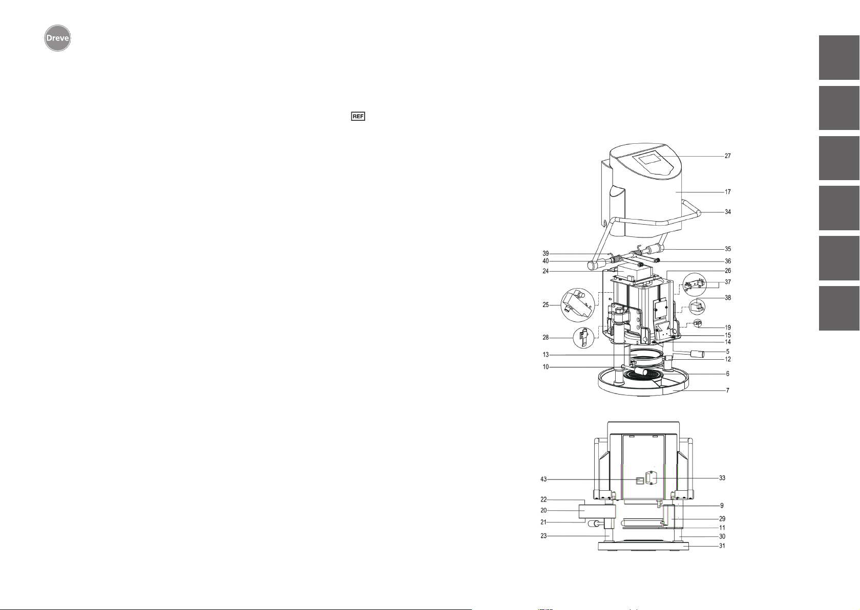
Drufosmart scan
16. Onderdelenlijst
Nr. Omschrijving
5 Handvat verwarming D6505519
6 Inzetschaal met noppenplaat 50591 / 50592
7 Schuiflade granulaat 5565
9 Drukluchtuitgang D6505536SM
10 Handvat draaischijf D6505519
11 Draaischijf D6505512
12 Ontluchtingsventiel 50761
13 Spanring D50038
14 Beschermglas scanner 1429
15 Scanner D6505541X1
17 Behuizing rood D65555RSCAN
Behuizing zilver D65555SSCAN
19 Microschakelaar 55790
20 Verwarmingsbehuizing D6505513
21 Kwarts-infrarood-straler D6505542
22 Temperatuursensor 5542
23 Zuil verwarmingselement 55773
24 Adapter D6505571
25 Magneetventiel 5202124
26 Cilinder 52019
27 Displayfolie kleefbaar 55810
28 Stoppositie draaischijf D6555344
29 Houder draaischijf D6505514
30 Zuil draaischijf 55772
31 Bodemplaat D6505511
33 Stroomaansluiting/zekeringhouder 51208
34 Activeringshendel D65885
35 Verbindingsstuk hendel/as D65017
36 Verloopbussen 55708
37 Eindschakelaar activeringshendel E5521
38 Eindschakelaar verwarming 55790
39 Terugpakveer 55861 / 55862
40 Heflus D6555847
43 Hoofdschakelaar 50841
zonder tekeningnummer
Stroomkabel Europa 51021
Stroomkabel Engeland 51284
Stroomkabel Amerika 51283
Elektronica incl. display, toetsenbord, verbindingskabel D6505530
Zekering F3,15 AT 51321
O-ringen 112 x 3 mm 51077
Kabelboom compleet 55520
Stoppositie Verwarming D65016
Besturingskaart D6505572X1
17. Explosionszeichung / Explosion sketch /
Dessin d’explosion / Despiece / Vista esplosa /
Afbeelding in vergroting
italiano español français english deutsch
nederlands
128
129
Page 66
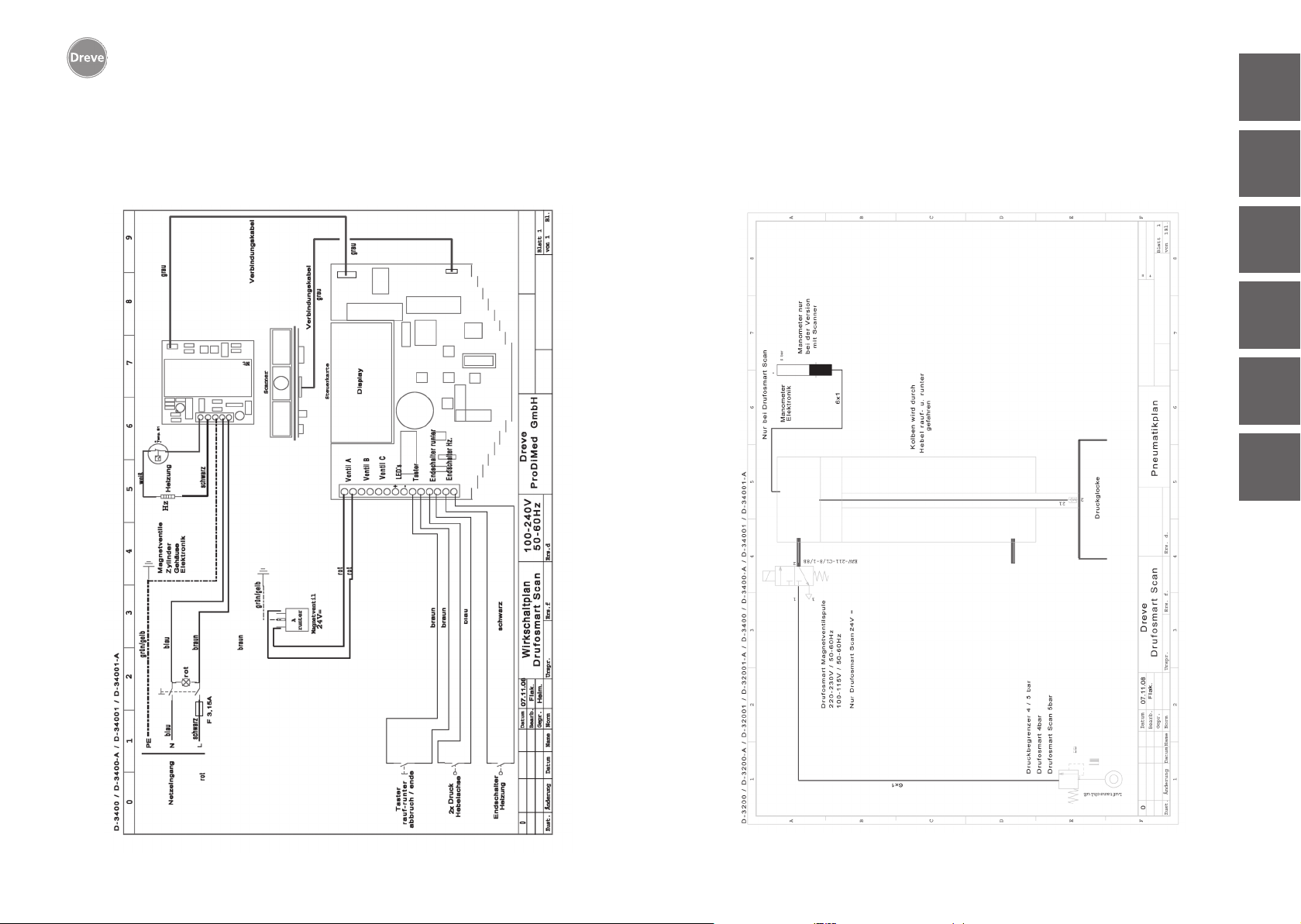
Drufosmart scan
18. Wirkschaltplan / Operating diagram / Diagramme /
Plano de circuitos detallado / Schema elettrico /
Schakelschema
19. Pneumatikplan / Pneumatic plan / Plan pneumatique
Plano neumático / Schema pneumatico /
Pneumatisch schema
italiano español français english deutsch
nederlands
130
131
Page 67
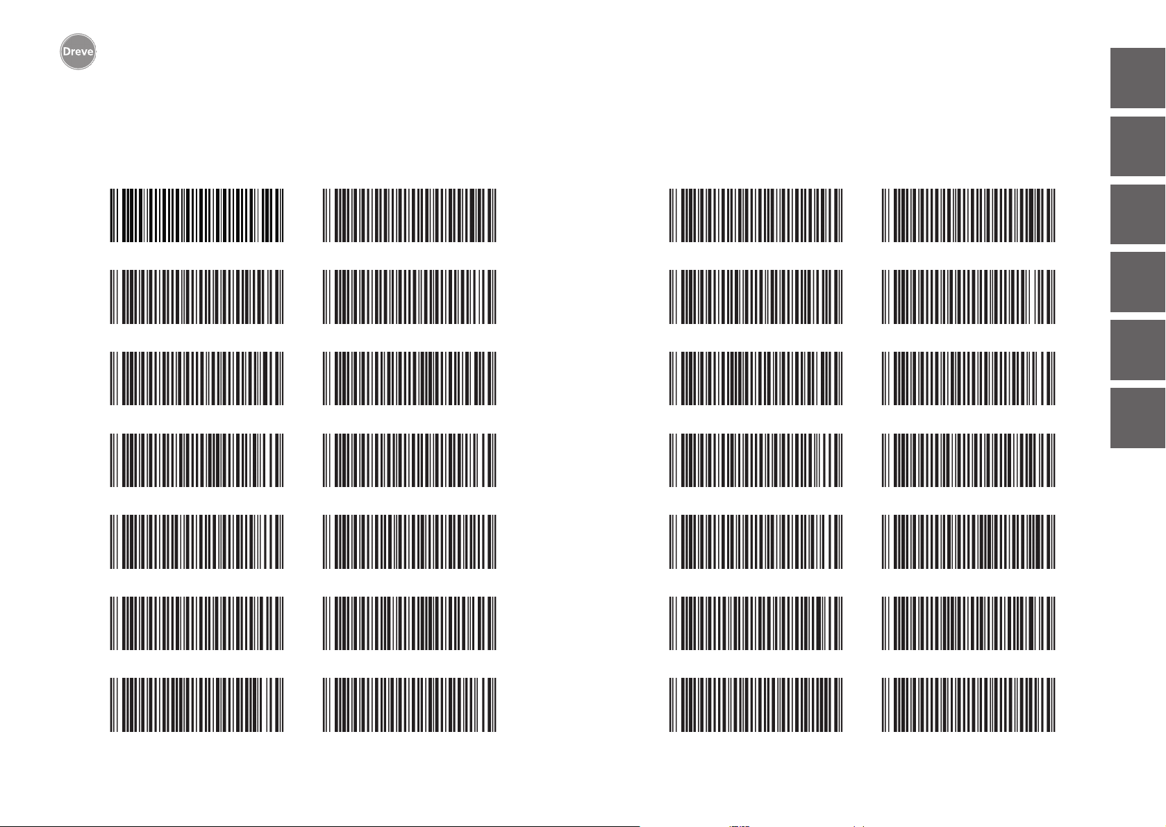
Drufosmart scan
20. Barcodes / Codes barrés / Código de barras /
Codici a barra
BioBleach hard 0,5
BioBleach soft 1,0
Biolit D 1,0
Biolit D 2,0
Biolon 0,5
Biolon 1,5
Biolon 2,0
Biolon 3,0
Drufolen H 0,6
Drufolen H 0,8
Drufolen W 0,65
Drufolen W 1,0
Drufoplast 2,0
Drufoplast rosa 3,0
Drufoplast transparent 3,0
Drufosoft 2,0
Drufosoft 3,0
italiano español français english deutsch
Drufosoft 4,0
nederlands
Drufosoft 5,0
Drufosoft pro 3,0
132
Biolon 0,75
Biolon 1,0
Drufolen W 0,8
Drufolen W 0,45
Drufosoft 1,0
Drufosoft 1,5
Kombiplast 1,8
Kombiplast 3,0
133
Page 68
Page 69
deutsch
Dreve Dentamid GmbH · Max-Planck-Straße 31 · 59423 Unna/Germany
Tel +49 2303 8807-0 · Fax: +49 2303 8807-55 · [email protected] · www.dentamid.dreve.com
 Loading...