

Drester Boxer Triple Combo DB33C, Boxer Triple Combo DI33C Operation Manual
1
16016 rev 2014-11-06
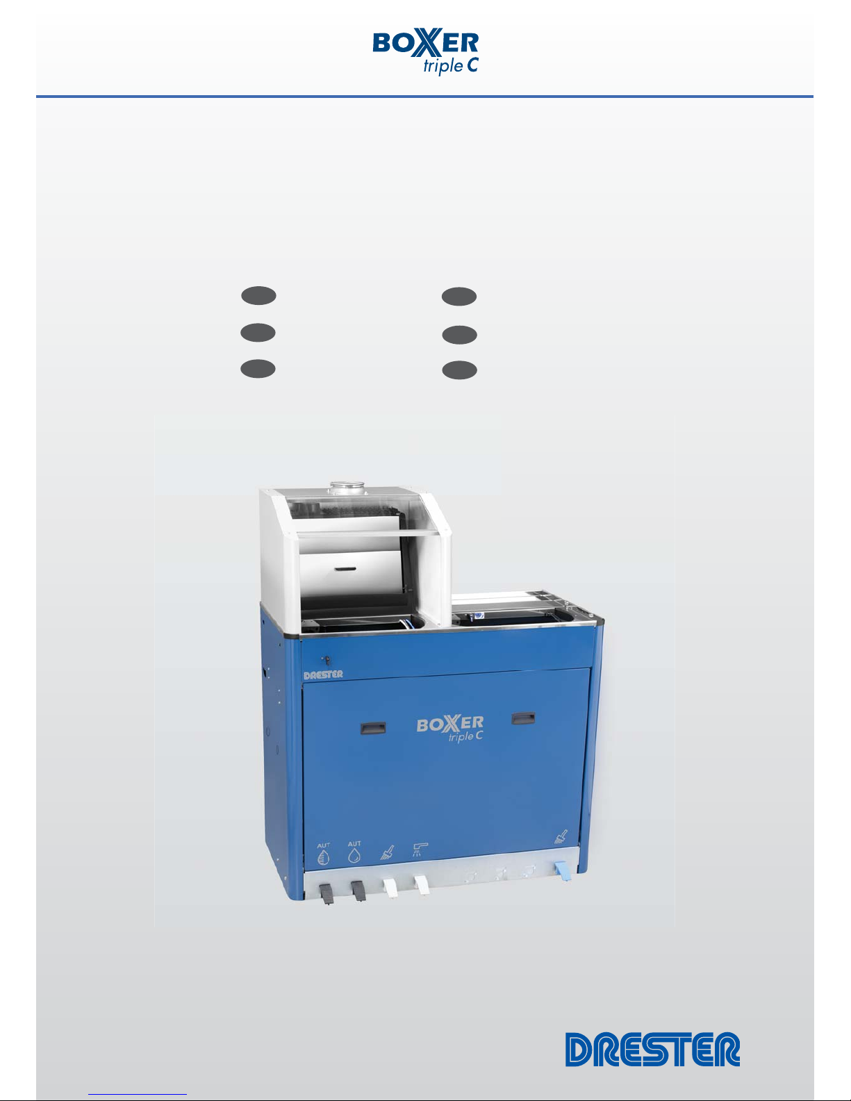
Drester Boxer Triple Combo
DB33C / DI33C
© Hedson Technologies AB 2012
16016 rev. 2014-11-06
Operation manual
Bedienungsanleitung
Mode d’emploi
ENG
DE
FR
SE
IT
ES
Bruksanvisning
Manuale d’uso
Manual de operación

2
16016 rev 2014-11-06
CONTENTS original language
GENERAL
Purpose of the machine ...........................................................3
Assembly .................................................................................3
Placing the Unit .......................................................................3
Installation ..............................................................................3
Permitted solvents ...................................................................4
Permitted solvent drums ..........................................................4
Collecting tray .........................................................................4
Preparation for use ..................................................................5
Service ....................................................................................5
Safety Information ...................................................................6
Technical data .........................................................................6
SPECIFIC FOR THE LEFT SIDE OF THE UNIT
Operating instructions ..............................................................7
SPECIFIC FOR THE RIGHT SIDE OF THE UNIT
Operation instructions ..............................................................7
The coagulation process ...........................................................8
Changing the fi lter ...................................................................8
INHALTSVERZEICHNIS
ALLGEMEINE INFORMATION
Verwendungszweck .................................................................9
Montage .................................................................................9
Aufstellung des Geräts .............................................................9
Installation ..............................................................................9
Zulässige Lösemittel ...............................................................10
Zulässige Lösemittelfässer ......................................................10
Auffangwanne .......................................................................11
Inbetriebnahme .....................................................................11
Wartung ................................................................................11
Sicherheitsinformationen........................................................12
Technische Daten ...................................................................12
LINKE SEITE DES GERÄTS
Betriebsanleitung ...................................................................13
RECHTE SEITE DES GERÄTS
Betriebsanleitung ...................................................................13
Der Koagulierungsprozess ......................................................14
Filtertausch ............................................................................14
SOMMAIRE
GÉNÉRALITÉS
Domaine
D’utilisation .............................................................15
Montage ...............................................................................15
Mise en place ........................................................................15
Installation ............................................................................16
Solvants autorisés ..................................................................16
Bidons de solvant autorisés ....................................................16
Bac récepteur ........................................................................17
Préparations pour l’utilisation ................................................17
Entretien ...............................................................................17
Informations de sécurité .........................................................18
Caractéristiques techniques ....................................................18
SPÉCIFIQUE POUR LE CÔTÉ GAUCHE DE L’UNITÉ
Instructions d’utilisation .........................................................19
SPÉCIFIQUE POUR LE CÔTÉ DROIT DE L’UNITÉ
Instructions d’utilisation .........................................................19
Le processus de coagulation ..................................................20
Changement de fi ltre .............................................................20
INNEHÅLLSFÖRTECKNING
ALLMÄN INFORMATION
Användningsområde ..............................................................21
Montering .............................................................................21
Placering ...............................................................................21
Installation ............................................................................22
Tillåtna lösningsmedel ...........................................................22
Tillåtna dunkar ......................................................................22
Uppsamlingskärl ....................................................................22
Idrifttagande .........................................................................23
Service ..................................................................................23
Säkerhetsinformation .............................................................24
Tekniska data ........................................................................24
SPECIFIKT FÖR DEN VÄNSTRA SIDAN AV MASKINEN
Bruksanvisning ......................................................................25
SPECIFIKT FÖR DEN HÖGRA SIDAN AV MASKINEN
Bruksanvisning ......................................................................25
Koaguleringsprocessen ..........................................................26
Byte av fi lter ..........................................................................26
INDICE
INFORMAZIONI GENERALI
Destinazione d’uso dell’apparecchio .......................................27
Montaggio ............................................................................27
Posizionamento .....................................................................27
Installazione ..........................................................................27
Solventi consentiti .................................................................28
Fusti di solvente consentiti .....................................................28
Vaschetta di raccolta ..............................................................29
Preparazioni per l’uso ............................................................29
Manutenzione .......................................................................29
Avvertenze di sicurezza ..........................................................30
Dati tecnici ............................................................................30
SPECIFICHE PER LA PAR TE SINISTRA DELLA MACCHINA
Istruzioni per l’uso .................................................................31
SPECIFICHE PER LA PAR TE DESTRA DELLA MACCHINA
Istruzioni per l’uso .................................................................31
Il processo di coagulazione ....................................................32
Sostituzione fi ltri ....................................................................32
CONTENIDO
GENERAL
Aplicaciones de la máquina ....................................................33
Montaje ................................................................................33
Ubicación de la unidad ..........................................................33
Instalación .............................................................................33
Disolventes permitidos ...........................................................34
Bidones para disolventes permitidos .......................................34
Bandeja de recolección ..........................................................34
Preparaciones para el uso ......................................................35
Mantenimineto ......................................................................35
Información de seguridad ......................................................36
Datos técnicos .......................................................................36
ESPECÍFICO PARA EL LADO IZQUIERDO DE LA UNIDAD
Instrucciones de operación .....................................................37
ESPECÍFICO PARA EL LADO DERECHO DE LA UNIDAD
Instrucciones de operación .....................................................37
El proceso de coagulación ......................................................38
Cambio del fi ltro ....................................................................38
ENG
DE
FR
SE
IT
ES

3
16016 rev 2014-11-06
GENERAL
PURPOSE OF THE MACHINE
The machine is intended for cleaning of air-driven spray-guns
that have been used for painting.
The left side of the unit has two separate areas for cleaning:
1. An automatic washer (items 1A illustration 1), intended for
cleaning of spray-guns with gravity fed paint-cups.
In this washer either
thinner-based solvents or water-
based solvents
can be used.
2. A sink (items 2A illustration 1), intended for manual
cleaning of other tools used in connection with vehicle
paint-jobs like: spray-guns with suction fed paint-cups, fi ller
scrapers, paint brushes and such.
In this sink either
thinner-based solvents or water-based
solvents
can be used.
The right side of the unit has one area for cleaning:
1 A sink (item 2B illustration 1), intended for manual cleaning
of air-driven spray-guns that have been used for painting
with water-based paints, as well as of other tools used in
connection with vehicle water-based paint-jobs like: fi ller
scrapers, paint brushes and such.
In this sink water only shall be used.
All other use of the unit are not allowed like:
– Cleaning of electric chargeable items
– Collecting of various waste
– Cleaning of textile materials
– Storing of items
– Cleaning of hands or other parts of the human body
– Cleaning of any items for food or drinks
The coagulation process described below (according to recommendations from the paint manufacturer) allows the cleaning
water to be re-used.
CHECK CAREFULLY WITH THE APPROPRIATE
AUTHORITY TO ENSURE THAT THE FILTERED WATER OBTAINED AFTER
THE COAGULATION PROCESS MAY BE EMPTIED INTO THE REGULAR
DRAIN-WATER SYSTEM. YOU MAY NEED INFORMATION FROM THE
PAINT MANUFACTURER WHEN DOING SO.
ASSEMBLY
– First of all, check if the machine has been damaged during
the transport. Remove the packaging and check again that
the machine has not been damaged during the transport. If
so, report this immediately to the transport company.
– Fit the fl ange for the extraction (item 3 illustration 1) with
the 4 screws included (see detail illustration 12)
– Fit the glass window into place (item 13 illustration 1) (see
detail illustration 13)
– The air-line on the left side of the unit (item 4 illustration 1)
is during transport placed inside the unit. Take it out, and
fasten it with the magnet in a convenient place on the left
side. The air-line can be routed either outside the side-wall,
or through the gap between the front lid and the side wall.
This air-line is intended to blow out the spray-gun after the
cleaning procedure.
– The air-gun on the right side of the unit (item 12 illustration
1) is during transport placed inside the unit. Take it out,
and fasten it with the magnet in a convenient place on the
right side. The air-line for the air-gun can be routed either
outside the side-wall, or through the gap between the front
lid and the side wall.
This air-gun is intended to blow the spray-gun dry after the
cleaning procedure.
PLACING THE UNIT
The DRESTER BOXER TRIPLE C is equipment Category 2 (ref.
ATEX-directive 94/9 EC) and may therefore be placed in locations classifi ed as Zone 1 (ref. ATEX-directive 1999/92 EC).
If the DRESTER BOXER TRIPLE C is installed in locations classifi ed as Zone 2 or in unclassifi ed locations, the following is
valid provided that the ventilation of the unit is installed as
described further down in this manual:
The space within 1 m of the DRESTER BOXER TRIPLE C is to be
classifi ed as Zone 2, and the inside of the ducting as Zone 1
(see illustration 17).
Within these areas, all equipment such as electrical items must
be approved for the Zones described. Equipment that generates
naked fl ames or sparks (e.g. welding or grinding equipment)
may not be used in this area. Smoking is not permitted. If in
any doubt, please contact the local fi re service authorities for
advice.
This manual is part of the unit and must be available at all
times.
INSTALLATION
Compressed air
The unit must be connected to compressed air of 7-12 bar
(110-180 psi). When in use, the unit consumes 150 litres/
min (6 cfm) of air (450 litres/min (16 cfm) if connected to a
DRESTER AIRVENT 11660).
The air is to be connected to the moisture trap inside the unit
(item 1 illustration 2). To access this point, remove the front
panel (item 5 illustration 1) by lifting it up-and-out.
The air-line can be led into this point via the slots on the side
of the unit, or through the open back of the unit. In either case,
make sure that the air-line do not bend the hoses or in any
other way harm the pneumatic system of the unit.
ENGLISH
Ref: Illustration attachment 17016

4
16016 rev 2014-11-06
To prevent pressure drops, the air line and couplings must be
adequately dimensioned. The regulator on the unit is pre-set to
6.5 bar (100 psi). This is the optimal setting and must not be
altered.
The compressed air supplied to the unit must be clean and dry.
If it is not fi rst led through a water trap and fi lter, it may cause
damage to the pneumatic components of the unit, which will
invalidate any warranty claims.
Fit a connector to the air-line on the left side of the unit (item 4
illustration 1). This air-line is intended to blow out the spraygun after the cleaning procedure.
Grounding the unit
Make sure that the unit is properly grounded by using the
grounding cable (item 6 illustration 2).
Ventilation
There are three different options for the unit’s ventilation.
For
all three options, it must be ensured that the speed of the
air fl ow at the opening of the hood is at least 0.5 m/s (this
corresponds to a ventilation volume of 400 m
3
/h (250 cfm)).
The ventilation must be connected in such a way as to ensure
the grounding of all parts.
Option 1: Connect the fl ange of the hood (item 3 illustration
1) directly to a metal ducting, which is in turn connected to a
ventilation system approved for Zone 1.
Option 2: Fit an air-driven AIRVENT 11660 to the hood and
connect this in turn to a metal ducting. This ducting can either
lead outdoors or be connected to a ventilation system approved
for Zone 1. The ducting must have a smooth inner surface, may
not be longer than 15 metres and shall be installed so that it is
as straight as possible.
Option 3: Connect the hood to an electric ventilator of a kind
like MINIVENT 2050 via a metal ducting. The exhaust from the
ventilator must be led outdoors.
PERMITTED SOLVENTS
The left side of the unit
This side can be used with solvents and solvent mixtures
intended for spray-gun cleaning, such as acetone, toluene,
isobutanol, xylene that are listed as Group IIA according to IEC
79-20 (EN 60079-20). Also water or water based solvents can
be used on this side.
Never use any solvent if it is not provided with an MSDS (Material Safety Data Sheet). Read the MSDS carefully, and follow all
the instructions and procedures provided in the MSDS. If unsure, or if more information is needed concerning the solvent,
please contact your solvent supplier.
Do not add other chemicals to the solvent including, but not
limited to, kerosene, gasoline, detergents, fuel oil or chlorinated
solvents.
The right side of the unit
In the Sink on this side (item 2B illustration 1) water only shall
be used.
General
All solvents must have a pH value between 4 and 10. Be sure
not to mix water-based solvents with thinner-based solvents. It
is important that all users are informed of what solvent is being
used, at all times.
PERMITTED SOLVENT DRUMS
The DRESTER BOXER TRIPLE C can be used with different types
of drums, but they must comply with the following:
– The drums must fi t into the unit
– The drums must be leak-free.
– The drums must be made of a conductive material.
– Check for local regulations concerning max allowed volume
for keeping solvent in the unit
Solvent drums are not provided by Hedson Technologies, thus
Hedson Technologies does not take any responsibility for the
drums. Follow the solvent supplier’s instructions carefully.
COLLECTING TRAY
The unit must be installed in such a way as to prevent accidental leakage of solvent or contaminated water from spreading
into a drain water system, thus representing a hazard to the
environment. This can be done by:
– installing the unit in a location where fl oor and walls can
hold any accidental drum leakage, or
– equipping the unit with a collecting tray beneath the sol-
vent drum and water container that is large enough to hold
the volume of at least one leaking item.

5
16016 rev 2014-11-06
PREPARATIONS FOR USE
Remove the front panel (item 5 illustration 1) by lifting it upand-out.
Remove the foot-pedal console (items 6 illustration 1) by lifting
it up and folding it out to the side (see illustration 2).
Solvent drums for the left side of the unit
Two drums are needed, one drum that is
empty, and one drum
full of solvent. Both drums must be of the same size, and they
must meet the requirements described under chapter PERMITTED SOLVENT DRUMS. Both drums must be clean on the inside
and they must not contain any solids or other objects that
could be sucked into the pumps when running.
Drum plugs
There are several types of solvent drums on the market, each
with different diameter of the opening. With the unit, a cardboard box with a selection of tapered plugs is supplied (see
illustration 3). Select the plug that fi t well into the opening of
the drums, and fi t them onto the drum adaptor of the hoses
(see illustration 4).
Solvent fi ll-up on the left side of the unit
Use one empty drum and another drum of the same size full of
clean solvent.
Place the empty drum to the left underneath the unit (item 2
illustration 2). Insert the group of hoses containing the drain
hose from the sink into this drum (item 4 illustration 2). Make
sure that the hoses are properly led well down into the drum,
and that the opening is well sealed by the tapered plug.
Take the second drum, the one full of solvent, and pour half of
its contents directly into the gun cleaner’s sink (item 2 illustration 1). The solvent that is poured in will drain into the drum
underneath the gun cleaner. Make sure to have the ventilation
running during this procedure.
Place the second drum, now half full, on the fl oor on the righthand side of the fi rst drum (item 3 illustration 2). Insert the
second group of hoses containing a white hose into this drum
(item 5 illustration 2). Make sure that the hoses are properly
led into the drum all the way down to the bottom, and that the
opening is well sealed by the tapered plug.
The solvent system is now fi lled-up. Both drums should be half
full. The left-hand drum, contains the solvent that will be recirculating for the automatic wash cycle, and the right-hand drum
contains clean solvent for rinsing. The contents of the right
drum will gradually be used up and transferred to the left drum.
Water
Fill the fi ltrate container (item 7 illustration 2) up to 100mm
(4”) under the upper edge with clean water.
Operating instructions
Operating instructions should be formulated on the basis of
this manual and translated into the language spoken by the
employees. It should always be available close to the machine.
To avoid confusion, the employees must be informed about the
solvent currently being used in the machine.
SERVICE
Weekly:
– Remove the strainers at the bottom of the automatic
washer (item 2 illustration 5) and clean it,
do not forget to
re-fi t it !
Monthly:
– Remove the fi ve nozzles in the automatic washer and clean
them with clean solvent. (see illustration 8).
When changing drums:
– Check and if necessary clean the strainers on the suction
hoses.
When changing fi lters:
– Check and if necessary clean the strainer on the suction
pipe(item 15 illustration 2) .
– Take out the fi ltrate container (item 7 illustration 2) and
empty it completely. Rinse it with water and wipe it off with
cloth or paper.
Every month:
– Change the water completely.

6
16016 rev 2014-11-06
SAFETY INFORMATION
Hazards may arise from improper use of the DRESTER BOXER
TRIPLE C. Hazards may also arise from improper choice/handling of drums or solvent. In order to maintain the high safety
standard of the unit, it is important that these instructions are
followed.
– Do not operate the unit until you have read and fully under-
stood this entire User’s Manual.
– The unit should be installed as described in the instructions.
– The unit should be used as described in the instructions.
– The unit should be maintained as described in the instruc-
tions.
– Only original spare parts may be used.
– This User’s Manual must be available and in legible condi-
tion in close proximity to the unit. Every user shall know
where to fi nd the User’s Manual.
– Operating instructions should be formulated on the basis of
this Users Manual, and translated into the language spoken
by the employees.
– Do not modify or in any way alter the unit.
– Do not operate the unit unless it is properly vented. Do not
operate the unit if the extraction of vapors is insuffi cient.
– Avoid contact with liquid and vapour. Refer to the solvents’
MSDS (Material Safety Data Sheet).
– Wear chemical goggles or similar, to protect your eyes.
Wear chemical-resistant gloves to prevent skin-contact.
Wear chemical-resistant clothing to protect against spills or
splash.
– Personnel suffering from respiratory problems or allergies to
solvents used, must not operate the machine.
– Clean up spills immediately.
– Do not smoke, eat or drink while close to the unit.
– The unit is equipped with a safety valve that will interrupt
the automatic wash cycle if the lid is opened before the
wash cycle is completed.
– Spray guns or any other paint equipment items cleaned
in the unit must be suitable for cleaning in a Zone 1 area
(ref. Category 2 according to EN 13463-1/2001). If unsure,
please contact the spray gun manufacturer.
– The unit must be properly grounded using the attached
grounding cable. If plastic drums are used, the openings
should be wiped off with a damp cloth, to avoid static
electricity, before inserting or removing any hoses or other
equipment.
TECHNICAL DATA
Manufacturer HEDSON TECHNOLOGIES AB
Hammarvägen 4
SE-232 37 Arlöv
Sweden
Tel.: +46-40- 53 42 00
Type of machine DRESTER BOXER TRIPLE C
Permitted solvents See section “Permitted Solvents”
Max solvent volume 30+ 30 litres
(Check for local regulations
concerning max allowed volume
for keeping solvent in the unit)
Maximum drum size 60 l
Compressed air needed 7-12 bar (110-180 psi)
90 l/min (3 cfm) pump only
370 l/min (14 cfm) including
AIRVENT 11660 in operation
Ventilation capacity required
400 m3/h (250 cfm)
Pump capacity 10 l/min
Solvent pressure 2 bar (30 psi)
Weight 90 kg (140 lb)
Overall dimensions Height: 1510 mm (59,5”)
Width: 1185 mm (46,7”)
Max depth: 650 mm (25,5”)
Depth at the fl oor: 610 mm (24”)
Extractor diameter 80 mm (7 3/16”)
Sound pressure level <70 dB(A)

7
16016 rev 2014-11-06
SPECIFIC FOR THE LEFT SIDE OF THE UNIT
OPERATING INSTRUCTIONS
Empty the spray-gun of any residual paint into a separate spillsdish.
Open the main valve for compressed air (item 7 illustration 1).
Open the lid for the automatic washer (make sure it `clicks` into
the full open position).
Place the spray-gun inside (see illustration 5).
Be sure to fi t the trigger clip following illustration 6, and to
push the spray-gun up against the nozzle for the paint-channel
(item 1 illustration 5) before you lock it into position with aid of
the magnets of the trigger clip.
If you prior to cleaning prefer to remove the Air-cap and the
needle of the spray-gun, then place those items as shown by
arrow 5 in illustration 5.
Close the lid, and start the automatic pre-wash cycle by pressing the foot pedal No.8A in illustration 1. The spray-gun will
now be automatically cleaned for approx. 1.5 minutes with
circulating solvent.
When the automatic pre-wash cycle is completed, the spraygun can be rinsed with clean solvent. The rinsing pump is
activated by pressing the foot pedal No. 9A in illustration 1,
and continues to work for as long as the pedal is depressed.
The pump will feed approx. 75 cc of solvent per pump stroke.
2-3 pump strokes are generally suffi cient for one rinse. Less if
the solvent has recently been changed.
When the cleaning procedure is completed, the lid can be
opened and the spray-gun taken out. It can now be manually
further washed or rinsed if required.
By pressing foot pedal No.10A in illustration 1 (NOTE: press it
all the way down !), recirculating solvent will be fed through
the brush placed in the sink (item 1 illustration 7A).
By pressing foot pedal No.11A in illustration 1, clean solvent
will be fed through the spray-nozzle placed in the sink (item 2
illustration 7A).
The brush and spray-nozzle in the sink can be used independently of the automatic washer at any time, provided that the
lid for the automatic washer is closed. The intensity of the spray
can be adjusted with the air-fl ow restrictor (item 1 illustration
14).
Connect the spray-gun to the air-line on the left side of the
machine (item 4 illustration 1), and blow out the spray-gun
through the funnel in the sink (item 3 illustration 7A). By using
this funnel, you prevent the fumes from spreading within the
premises.
Finally, the spray-gun can be blown dry by using the air-gun on
the right side of the unit (item 12 illustration 1).
Close the lid after cleaning.
SPECIFIC FOR THE RIGHT SIDE OF THE UNIT
OPERATING INSTRUCTIONS
Empty the spray-gun of any residual paint into a separate spillsdish.
Open the main valve for compressed air (item 7 illustration 1).
Open the lid for the manual sink.
By pressing foot pedal No.10B in illustration 1, recirculating
water will be fed through the cleaning brush placed in the sink
(item 1 illustration 7B). Note that the ball-valve on the brush
(item 6 illustration 7B) must be in an open position. Use the
cleaning brush to clean the spray-gun.
The spray-gun’s paint channel can now be rinsed with clean
water. Press the tapered nozzle of the rinse-gun (item 2 illustration 7B) against the paint channel of the spray-gun. Pull the
triggers on the spray- and rinse-guns simultaneously. Then rinse
the outside of the spray-gun with the rinse-gun.
When using the rinse-gun, the ball-valve on the wash-brush
should be in a closed position.
The brush and rinse-gun in the sink can be used independently
of the automatic washer at any time.
Connect the spray-gun to the air-line on the left side of the
machine (item 4 illustration 1), and blow out the spray-gun
through the funnel in the sink (item 3 illustration 7B). By using
this funnel, you prevent the fumes from spreading within the
premises.
Finally, the spray-gun can be blown dry by using the air-gun on
the right side of the unit (item 12 illustration 1).

8
16016 rev 2014-11-06
THE COAGULATION PROCESS
1. CHECKING THE FILTRATE CONTAINER
When the water level reaches the level of the working platform
(item 4 illustration 7B), it is time to perform the coagulation
process.
First check that the remaining content of the fi ltrate container
(item 7 illustration 2) is not higher than 25mm (1”).
2. COAGULATION
N.B.: IT IS ABSOLUTELY VITAL THAT THE COAGULATION PROCESS IS
CARRIED OUT WITH THE GREATEST CARE, SO THAT LARGE FLOCKS
OF COAGULATED PAINT ARE FORMED. OTHERWISE THE FILTERS WILL
IMMEDIATELY BECOME OBSTRUCTED, AND CANNOT BE RE-USED.
A: Remove the working platform (item 4 illustration 7B).
B: Open the valve for the water agitator (item 5 illustration
7B).
C: Add the coagulation powder as recommended by the paint
manufacturer.
D: Stir the powder with a stick for a moment to avoid that it
sinks down to the bottom in lumps.
D: Allow the agitator to run for a few minutes.
E: Stop the agitator occasionally for around 30 seconds since
this improves the coagulation process. The total coagula-
tion time is around 3-4 min, depending on the amount of
powder, the level of contamination, etc.
When this is done, close the valve for the agitator.
3. FILTRATION
Open the drain-valve (item 10 illustration 2) and drain the
wash-basin completely into the fi lter (item 11 illustration 2).
Clean the inside of the wash-basin thoroughly with the cleaning brush (i.e. with recycled water), so that any remains of
residual fl ocks are completely drained into the fi lter.
When this is done, close the drain-valve
CHANGING THE FILTER
N.B.: MAKE SURE THAT YOU USE ORIGINAL DRESTER FILTERS,
NR. 8701 (FINE FILTER), AND NR. 8702 (PRIMARY FILTER).
THESE FILTERS HAVE BEEN TESTED AND APPROVED BY THE
PAINT MANUFACTURERS.
The primary fi lter (item 2 illustration 11) collects most of the
coagulated sludge, while the fi ne fi lter (item 1 illustration 11)
collects the fi ner paint particles.
Remove the sludge from the primary fi lter after each coagulation process (once it is completely dry, the sludge is easy to
remove from the fi lter). By doing so the primary fi lter can be
re-used up to 10 times.
The fi ne fi lter will gradually become blocked after trapping the
fi ner paint particles. In general, the fi ne fi lter can be used for
up to 5 coagulation processes. The fi ne fi lter must however be
changed every 1-2 months, otherwise there is a risk that mould
will develop.
N.B.: THE COAGULATION SLUDGE MUST BE HANDLED IN ACCORDANCE WITH REGULATIONS FROM THE APPROPRIATE AUTHORITY.
INFORMATION FROM THE PAINT SUPPLIER MAY BE NECESSARY.

9
16016 rev 2014-11-06
ALLGEMEINE INFORMATION
VERWENDUNGSZWECK
Reinigung von druckluftbetriebenen Farbspritzpistolen, die zum
Lackieren benutzt wurden.
Die linke Seite des Geräts hat zwei getrennte Reinigungs-
bereiche:
1. Eine automatische Waschkammer (Teil 1 A Abbildung 1),
zur Reinigung von Fließbecherpistolen.
In dieser Waschkammer dürfen
Waschverdünnung oder
Lösemittel auf Wasserbasis
verwendet werden.
2. Ein Waschbecken (Teil 2A Abbildung 1), zur manuellen
Reinigung anderer Werkzeuge, die bei Lackierarbeiten
benutzt werden z.B.: Saugbecherpistolen, Spatel, Pinsel und
ähnliche.
In diesem Waschbecken dürfen
Lösemittel auf Verdünner-
basis oder Lösemittel auf Wasserbasis
verwendet werden.
Die
rechte Seite des Geräts hat einen Reinigungsbereich:
1 Ein Waschbecken (Teil 2 B Abbildung 1), zur manuellen
Reinigung von druckluftbetriebenen Farbspritzpistolen, die
zum Lackieren mit wasserbasierenden Lacken verwendet
wurden, ebenso wie andere Werkzeuge, die mit wasser-
basierenden Lacken für Fahrzeug-Lackierarbeiten benutzt
werden, wie z.B.: Spatel, Pinsel und Ähnliches.
In diesem Waschbecken darf
nur Wasser verwendet wer-
den.
Für folgende Anwendungen darf das Gerät nicht verwendet
werden:
– Leeren überschüssiger Farbe in das Gerät
– Reinigung von elektrisch betriebenen Geräten
– Sammeln von verschiedenen Abfallarten
– Reinigung von Textilien
– Aufbewahrung von Gegenständen
– Reinigung der Hände oder anderer Teile des menschlichen
Körpers
– Reinigung von Gegenständen die für Essen und Trinken
verwendet werden
Der Koagulationsprozess (laut Empfehlung des Lackherstellers) ermöglicht die Wiederverwendung des Waschwassers.
BEI DER ZUSTÄNDIGEN BEHÖRDE BESTÄTIGEN LASSEN, DASS DAS
FILTRATWASSER NACH DER KOAGULATION UND FILTRATION IN DAS
ABWASSERSYSTEM EINGELEITET WERDEN DARF. DAFÜR BENÖTIGEN
SIE INFORMATIONEN IHRES FARBHERSTELLERS.
MONTAGE
– Prüfen Sie als erstes, ob die Maschine während des
Transports beschädigt wurde. Entfernen Sie die Verpackung
und überprüfen Sie nochmals, ob die Maschine während
des Transports beschädigt wurde. Wenn ja, melden Sie dies
sofort dem Transportunternehmen.
– Montieren sie den Flansch für die Absaugung (Teil 3
Abbildung 1) mit den 4 mitgelieferten Schrauben (siehe
detaillierte Abbildung 12)
– Setzen Sie das Glasfenster in Position (Teil 13 Abbildung 1)
(siehe detaillierte Abbildung 13)
– Die Luftleitung auf der linken Seite des Geräts (Teil 4 Abbil-
dung 1) befi ndet sich während des Transports im Inneren
des Geräts. Nehmen Sie sie heraus und befestigen Sie sie
mit dem Magneten an einer geeigneten Stelle auf der
linken Seite. Die Luftleitung kann entweder außerhalb der
Seitenwand oder durch den Spalt zwischen Vorderdeckel
und Seitenwand geführt werden.
Diese Luftleitung ist zum Ausblasen der Spritzpistole nach
dem Reinigungsvorgang gedacht.
– Die Luftpistole auf der rechten Seite des Geräts (Teil 12
Abbildung 1) befi ndet sich während des Transports im Inneren des Geräts. Nehmen Sie sie heraus und befestigen Sie
sie mit dem Magneten an einer geeigneten Stelle auf der
rechten Seite. Die Luftleitung kann entweder außerhalb der
Seitenwand oder durch den Spalt zwischen Vorderdeckel
und Seitenwand geführt werden.
Diese Luftpistole ist zum Trockenblasen der Spritzpistole
nach dem Reinigungsvorgang gedacht.
AUFSTELLUNG DES GERÄTS
Der DRESTER BOXER TRIPLE C entspricht der Gerätekategorie „2“
(ATEX-Richtlinie 94/9 EG) und darf demnach in einem Arbeitsraum Zone 1 (ATEX-Richtlinie 1999/92 EG) aufgestellt werden.
Sollte der DRESTER BOXER TRIPLE C in einen Arbeitsraum Zone
2 oder in einem unklassifi zierten Bereich aufgestellt werden,
gelten die folgenden Defi nitionen , sofern die Absaugung des
Gerätes wie weiter unten in diesem Handbuch beschrieben
installiert ist:
Der Bereich 1 m ringsum der DRESTER XXXX, ist als Zone 2 zu
betrachten und die Innenseite der Absaugleitung als Zone 1
(siehe Abbildung 17).
In diesen Bereichen muss alle Ausstattung wie z.B. elektrische
Betriebsmittel für die entsprechende Zone zugelassen sein. Geräte, die offene Flammen oder Funken erzeugen (z. B. Schweißoder Schleifgeräte) dürfen in diesem Bereich nicht verwendet
werden. Rauchen ist nicht erlaubt. Im Zweifelsfall fragen Sie bei
Ihrer örtlichen Brandschutzbehörde nach.
Diese Bedienungsanleitung ist Bestandteil des Gerätes und
muss jederzeit verfügbar sein.
INSTALLATION
Druckluft
Das Gerät muss an Druckluft mit 7-12 bar (110-180 psi)
angeschlossen werden. Im Betrieb verbraucht das Gerät 150
Liter / min Luft (6 cfm) oder 450 Liter / min (16 cfm), wenn eine
DEUTSCH
Hinweiss: Bildbeilage 17016

10
16016 rev 2014-11-06
DRESTER AIRVENT 11660 angeschlossen ist.
Die Luft muss an den Wasserabscheider im Inneren des Geräts
angeschlossen werden (Teil 1 Abbildung 2). Um an diese Stelle
zu kommen, entfernen Sie die Frontblende (Teil 5 Abbildung 1)
indem Sie diese hoch und dann heraus heben.
Die Luftleitung kann in diesen Punkt durch die Schlitze an der
Seite des Geräts oder durch die offene Rückseite des Geräts
geführt werden. Stellen Sie in jedem Fall sicher, dass die Luftleitung nicht die Luftschläuche des Gerätes verbiegt oder in sonstiger Weise das pneumatische System des Gerätes beschädigt.
Um Druckverluste zu vermeiden müssen die Luftleitung und
Kupplungen ausreichend dimensioniert sein. Der Druckregler
am Gerät ist auf 6,5 bar (100 psi) voreingestellt. Dies ist die
optimale Einstellung und darf nicht verändert werden.
Es darf nur trockene und gereinigte Druckluft verwendet
werden. Wenn die Luft vorher nicht durch einen Wasserabscheider und einen Filter geleitet wird, können die pneumatischen
Komponenten beschädigt werden und die Herstellergarantie
erlischt.
Montieren Sie eine Kupplung auf die Luftleitung auf der linken
Seite des Geräts (Teil 4 Abbildung 1). Diese Luftleitung ist zum
Ausblasen der Spritzpistole nach dem Reinigungsvorgang
geeignet.
Erdung des Geräts
Stellen Sie sicher, dass das Gerät ordnungsgemäß mit dem
Erdungskabel (Teil 6 Abbildung 2) geerdet ist.
Belüftung
Es gibt drei verschiedene Optionen für die Belüftung des
Geräts.
Für alle drei Optionen muss sichergestellt werden,
dass die Geschwindigkeit des Luftstroms an der Öffnung der
Haube mindestens 0,5 m/s beträgt (dies entspricht einem
Belüftungsvolumen von 400 m
3
/h (250 cfm)). Die Absaugung
muss so angeschlossen sein, dass sie die Erdung aller Teile
gewährleistet.
Option 1: Verbinden Sie den Flansch der Haube (Teil 3 Abbildung 1) direkt mit einer Metall-Rohrleitung, die wiederum mit
einem für Zone 1 zugelassenen Ventilationssystem verbunden
ist.
Option 2: Bringen Sie einen druckluftbetriebenen AIRVENT
11660 an der Haube an, und verbinden Sie diesen wiederum
mit einer Metall-Leitung. Diese Metall-Leitung kann entweder
in den Außenbereich gelegt oder mit einem für Zone 1 genehmigten Ventilationssystem verbunden werden. Die MetallRohrleitung muss eine glatte Innenfl äche haben, darf nicht
länger als 15 m sein und sollte so gerade wie möglich installiert
werden.
Option 3: Schließen Sie die Haube an einen elektrischen Ventilator der Art des MINIVENT 2050 über eine Metall-Rohrleitung
an. Die Auslassöffnung des Ventilators muss ins Freie führen.
ZULÄSSIGE LÖSEMITTEL
Die linke Seite des Geräts
Diese Seite kann mit Lösemitteln und Mischungen von
Lösemitteln wie z.B. Aceton, Toluol, Isobutanol, Xylol, die laut
IEC 79-20 (EN 60079-20) der Gruppe IIA zugeordnet sind,
zur Reinigung von Spritzpistolen verwendet werden. Wasseroder Wasserbasierte Lösemittel können auch auf dieser Seite
verwendet werden.
Benutzen Sie kein Lösemittel, welches nicht im SDB (Sicherheitsdatenblatt) angegeben ist. Lesen Sie das SDB sorgfältig
durch und befolgen Sie die darin angegebenen Anweisungen
und Verfahren. Wenn Sie unsicher sind oder wenn mehr Informationen zu einem Lösemittel benötigt werden, wenden Sie
sich bitte an Ihren Lösemittel-Lieferanten.
Fügen Sie keine anderen Chemikalien zum Lösemittel hinzu,
einschließlich, aber nicht beschränkt auf, Kerosin, Benzin, Reinigungsmittel, Heizöl oder chlorhaltige Lösemittel.
Die rechte Seite des Geräts
Im Waschbecken auf dieser Seite (Teil 2 B Abbildung 1) darf nur
Wasser verwendet werden.
Allgemein
Alle Lösemittel müssen einen pH-Wert zwischen 4 und 10
haben. Achten Sie darauf keine wasserbasierten Lösemittel
mit verdünnten Lösemitteln zu mischen. Es ist wichtig, dass
alle Benutzer zu jeder Zeit über das verwendete Lösemittel
informiert sind.
ZULÄSSIGE LÖSEMITTELFÄSSER
Der DRESTER BOXER TRIPLE C kann mit verschiedenen Fässertypen betrieben werden, die aber folgende Voraussetzungen
erfüllen müssen:
– Die Fässer müssen in das Gerät passen
– Die Fässer müssen dicht sein.
– Die Fässer müssen aus einem leitfähigen Material bestehen.
– Erkundigen Sie sich nach den örtlichen Vorschriften bezüg-
lich des maximal erlaubten Volumens der Lösemittelmenge,
die das Gerät enthalten darf
Lösemittelfässer werden nicht von Hedson Technologies angeboten, somit übernimmt Hedson Technologies auch keinerlei
Verantwortung für die Fässer. Befolgen Sie sorgfältig die Anweisungen des Lösemittel-Lieferanten.

11
16016 rev 2014-11-06
AUFFANGWANNE
Das Gerät darf nur so aufgestellt und betrieben werden, dass
ein unkontrolliertes Auslaufen des Lösemittels und eine Wasserverschmutzung durch Verteilen im Abwassersystem verhindert
wird und keine Umweltgefährdung hervorgerufen wird. Dafür
kann folgendermaßen gesorgt werden:
– Bauen Sie das Gerät an einem Ort auf, wo Boden und Wän-
de versehentlich auslaufende Flüssigkeit auffangen können
– Statten Sie das Geräts unterhalb des Lösemittelfasses
mit einer Auffangwanne aus, die groß genug ist, um das
gesamte Volumen eines Fasses aufzufangen.
INBETRIEBNAHME
Entfernen Sie die Frontblende (Teil 5 Abbildung 1), indem Sie
sie hochschieben und herausnehmen.
Entfernen Sie die Fußpedalkonsole (Teil 6 Abbildung 1) indem
Sie sie hochschieben und zur Seite herausklappen (siehe Abbildung 2).
Lösemittelfässer für die linke Seite des Geräts
Zwei Fässer werden benötigt, ein Fass, das
leer ist und ein Fass
voll mit Lösemittel. Beide Fässer müssen die gleiche Größe
haben
und die Anforderungen aus Kapitel ZULÄSSIGE LÖSEMITTELFÄSSER erfüllen. Beide Fässer müssen auf der Innenseite
sauber sein und dürfen keine Feststoffe oder andere Dinge
enthalten, welche während des Betriebs in die Pumpen gesaugt
werden könnten.
Stopfen für die Fassöffnung
Es gibt mehrere Arten von Lösemittelfässern auf dem Markt,
jeweils mit unterschiedlich großem Öffnungsdurchmesser. Das
Gerät wird mit einer Auswahl konischer Stopfen geliefert (siehe
Abbildung 3). Wählen Sie den Stopfen, der am besten in die
Fassöffnung passt und stecken Sie ihn auf den Fass-Adapter der
Schläuche (siehe Abbildung 4).
Lösemittel nachfüllen auf der linken Seite des Geräts
Verwenden Sie ein leeres Fass und ein Fass der selben Größe
gefüllt mit sauberem Lösemittel.
Stellen Sie das linke, leere Fass unter das Gerät (Teil 2 Abbildung 2). Legen Sie die Gruppe von Schläuchen mit dem Ablaufschlauch vom Waschbecken in dieses Fass (Teil 4 Abbildung 2).
Stellen Sie sicher, dass die Schläuche richtig weit unten in das
Fass geführt werden und dass die Öffnung gut versiegelt ist mit
dem sich verjüngenden Stopfen.
Nehmen Sie das zweite Fass, welches mit Lösemittel gefüllt ist,
und füllen Sie die Hälfte des Inhalts direkt in das linke Waschbecken des Pistolenreinigers(Teil 2 Abbildung 1). Das Lösemittel, welches hinein fl ießt, wird weiter in das Fass unterhalb des
Pistolenreinigers abfl ießen. Stellen Sie sicher, dass die Ventilation währenddessen an ist.
Stellen Sie das zweite Fass, das nun halb voll ist, auf den Boden
rechts vom ersten Fass (Teil 3 Abbildung 2). Legen Sie die zweite Gruppe von Schläuchen, die einen weißen Schlauch enthält,
in dieses Fass (Teil 5 Abbildung 2). Stellen Sie sicher, dass die
Schläuche richtig weit unten in das Fass geführt werden und
dass die Öffnung gut versiegelt ist mit dem sich verjüngenden
Stopfen.
Das Lösemittelsystem ist nun aufgefüllt. Beide Fässer sollten
zur Hälfte gefüllt sein. Das linke Fass enthält das Lösemittel,
das im automatischen Waschgang rezirkuliert, und das rechte
Fass enthält sauberes Lösemittel zum Spülen. Der Inhalt dieses
Fasses wird nach und nach aufgebraucht werden und fl ießt in
das linke Fass ab.
Wasser
Den Filtratbehälter (Teil 7 Abbildung 2) bis zu 100 mm (4”)
unterhalb des oberen Rands mit sauberem Wasser auffüllen.
Betriebsanleitung
Betriebsanweisungen sollten auf der Basis dieser Betriebsanleitung formuliert und in die Sprache, die die Angestellten
sprechen, übersetzt werden. Es sollte stets in der Nähe des
Geräts verfügbar sein. Um Verwirrung zu vermeiden, müssen
die Mitarbeiter über das derzeit in der Maschine verwendete
Lösemittel informiert werden.
WARTUNG
Wöchentlich
– Entfernen Sie das Sieb am Boden der automatischen
Waschkammer (Teil 2 Abbildung 5) und reinigen Sie es,
vergessen Sie nicht, es wieder einzusetzen!
Monatlich
– Demontieren Sie die fünf Düsen in der automatischen
Waschkammer, und reinigen Sie sie mit sauberem Lösemittel. (siehe Abbildung 8).
Beim Wechsel der Fässer
– Überprüfen und wenn nötig reinigen Sie die Siebe auf den
Saugschläuchen.
Beim Wechsel der Filter
– Überprüfen und wenn nötig reinigen Sie das Sieb auf dem
Saugrohr (Teil 15 Abbildung 2).
– Nehmen Sie den Filterbehälter (Teil 7 Abbildung 2) heraus
und leeren Sie ihn vollständig aus. Spülen Sie ihn mit Wasser aus und wischen Sie ihn mit einem Tuch oder Papier ab.
Jeden Monat
– Wechseln Sie das Wasser vollständig aus.

12
16016 rev 2014-11-06
SICHERHEITSINFORMATIONEN
Es können Risiken durch unsachgemäße Handhabung des
DRESTER BOXER TRIPLE C entstehen. Risiken können auch bei
ungeeigneter Wahl / Handhabung von Fässern oder Lösemittel
entstehen. Um den hohen Sicherheitsstandard des Geräts zu erhalten, ist es wichtig, dass diese Anweisungen befolgt werden.
– Benutzen Sie dieses Gerät nicht, wenn Sie die Betriebsanlei-
tung nicht vollständig gelesen und verstanden haben.
– Das Gerät sollte wie in der Anleitung beschrieben installiert
werden.
– Das Gerät sollte verwendet werden, wie in der Anleitung
beschrieben.
– Das Gerät sollte wie in der Anleitung beschrieben gewartet
werden.
– Es dürfen nur Original-Ersatzteile verwendet werden.
– Diese Betriebsanleitung muss verfügbar und in lesbarem
Zustand in der Nähe des Geräts sein. Jeder Benutzer muss
wissen, wo die Bedienungsanleitung zu fi nden ist.
– Betriebsanweisungen sollten auf der Basis dieser Betriebs-
anleitung formuliert und in die Sprache, die die Angestellten
sprechen, übersetzt werden.
– Ändern Sie das Gerät auf keinen Fall ab oder um.
– Betreiben Sie das Gerät nicht ohne es angemessen zu be-
lüften. Betreiben Sie das Gerät nicht, wenn die Ventilation
unzureichend ist.
– Vermeiden Sie den Kontakt mit Reinigungsfl üssigkeit und
Dämpfen. Sehen Sie im SDB (Sicherheitsdatenblatt) der
Lösemittel nach.
– Tragen Sie chemische Schutzbrillen oder Ähnliches, um
Ihre Augen zu schützen. Tragen Sie chemisch-resistente
Handschuhe, um Hautkontakt zu vermeiden. Tragen Sie
chemisch-resistente Kleidung, um sich vor Flecken oder
Spritzern zu schützen.
– Mitarbeiter mit Atemwegs-Problemen oder Lösemittel-
Allergien dürfen die Maschine nicht bedienen.
– Beseitigen Sie Verschüttetes sofort.
– Rauchen, essen oder trinken Sie nicht, wenn Sie in der
Nähe des Geräts sind.
– Das Gerät ist mit einem Sicherheitsventil versehen, welches
den automatischen Waschzyklus unterbricht, wenn der
Deckel vor dem Ende des Waschzyklus geöffnet wird.
– Spritzpistolen oder jede andere Lackier-Ausrüstung, welche
im Gerät gereinigt werden, müssen für die Reinigung in
Zone 1 zugelassen sein (Ref. Kategorie 2 gemäß EN 13463-
1/2001). Wenn Sie unsicher sind, kontaktieren Sie bitte den
Spritzpistolen-Hersteller.
– Das Gerät muss ordnungsgemäß mit dem beiliegenden
Kabel geerdet sein. Wenn Kunststoff-Fässer verwendet
werden, sollten die Öffnungen mit einem feuchten Tuch
abgewischt werden, um statische Aufl adung zu vermeiden,
vor dem Einsetzen oder Entfernen von Schläuchen oder
anderen Geräten.
TECHNISCHE DATEN
Hersteller HEDSON TECHNOLOGIES AB
Hammarvägen 4
SE-232 37 Arlöv
Schweden
Tel.: +46-40- 53 42 00
Geräte-Typ DRESTER BOXER TRIPLE C
Zulässige Lösemittel Siehe Sektion “Genehmigte Lösemittel”
Maximales
Lösemittelvolumen 30+ 30 Liter
(Erkundigen Sie sich nach den örtlichen
Vorschriften bezüglich des maximal
erlaubten Lösemittel-Volumens, das im
Gerät enthalten sein darf)
Maximale Fassgröße 60 l
Benötigte Druckluft 7-12 bar (110-180 psi)
90 l/min (3 cfm) nur Pumpe
370 l/min (14 cfm) mit AIRVENT 11660
in Betrieb
Erforderliche
Ventilationskapazität 400 m
3
/h (250 cfm)
Pumpenkapazität: 10 l/min
Lösemittel-Druck 2 bar (30 psi)
Gewicht 90 kg (140 lb)
Gesamtmaße Höhe: 1510 mm (59,5”)
Breite: 1185 mm (46,7”)
Maximale Tiefe: 650 mm (25,5”)
Tiefe am Boden: 610 mm (24”)
Extraktor-Durchmesser 80 mm (7 3/16”)
Schalldruckpegel <70 dB(A)
 Loading...