

Dressler CESAR 1312 User Manual
User Manua
l
CESAR™
Generator
Model 1312
service@dressler.com


User Manual
CESAR™ Generator
Model 1312
CESAR 1312 (E)
Dressler®HF-Technik GmbH
COPYRIGHT
This manual and the information contained herein is the proprietary property
®
of Dressler
HF-Technik GmbH.
No part of this manual may be reproduced or copied without the express
®
written permission of Dressler
HF-Technik GmbH. Any unauthorized use of
this manual or its contents is strictly prohibited. Copyright
®
Dressler
HF-Technik GmbH. All Rights Reserved.
DISCLAIMER AND LIMITATION OF LIABILITY
The information contained in this manual is subject to change by
Dressler
Technik GmbH makes no warranty of any kind whatsoever, either expressed
or implied, with respect to the information contained herein. Dressler
Technik GmbH shall not be liable in damages, of whatever kind, as a result of
the reliance on or use of the information contained herein.
®
HF-Technik GmbH without prior notice. Dressler®HF-
PRODUCT USAGE STATEMENT
©
2003
®
HF-
Read this entire manual and all other publications pertaining to the work to be
performed before you install, operate, or maintain this equipment. Practice all plant
and product safety instructions and precautions. Failure to follow instructions can
cause personal injury and/or property damage. If the equipment is used in a manner
not specified by the manufacturer, the prot ec tion provid ed by t he equipment may be
impaired. All personnel who work with or who are exposed to this equipment must
take precautions to pr otect themselves a gainst serious or possibly f at al bodily inju ry.
Dressler
hazards, but it assumes no responsibility for the after-sale operation of the
equipment or the safety practices of the owner or user. This equipment produces or
uses potentially lethal high-voltage, high-current, radio frequency (RF) energy.
NEVER DEFEAT INTERLOCKS OR GROUNDS.
®
HF-Technik GmbH provides information on its products and associated
ii CESAR 1312 (E)

TRADEMARKS
CESAR™ is a trademark of Dressler
Internet Explorer
Corporation.
Microsoft
Modbus
Smith
license from Analog Instruments Company, New Providence, New
Jersey 07974.
Windows NT
Windows
CESAR™ 1312 Generator
®
is a registered trademark of Dressler®HF-
Technik G mbH.
®
HF-Technik GmbH.
®
is a registered trademark of the Microsoft
®
is a registered trademark of the Microsoft Corporation.
®
is a registered trademark of Gould, Inc.
®
The Smith® chart shown is produced under a copyright
®
is a registered trademark of the Microsoft Corporation.
®
is a registered trademark of the Microsoft Corporation.
CUSTOMER FEEDBACK
Dressler®HF-Technik GmbH’s technical writing staff has carefully developed
this manual using research-based document design principles. However,
improvement is ongoing, and the writing staff welcomes and appreciates
customer feedback. Please send any comments on the content, organization,
or format of this user manual to:
• tech.writing@aei.com
To order a manual, please contact the Dressler Customer Service
Department:
• service@dressler.com
CESAR 1312 (E) iii

Dressler®HF-Technik GmbH
iv CESAR 13 12 (E)

CESAR™ 1312 Generator
Table of Contents
Chapter 1. Safety and Product Compliance Guidelines
Important Safety Information . . . . . . . . . . . . . . . . . . . . . . . . . . . . . . . . . . . . . . . . .1-1
Interpreting the Manual . . . . . . . . . . . . . . . . . . . . . . . . . . . . . . . . . . . . . . . . . . . . .1-1
This Revision of the Manual . . . . . . . . . . . . . . . . . . . . . . . . . . . . . . . . . . . . . .1-1
Understanding Model 1312 Options . . . . . . . . . . . . . . . . . . . . . . . . . . . . . . . .1-2
Type Conventions . . . . . . . . . . . . . . . . . . . . . . . . . . . . . . . . . . . . . . . . . . . . . .1-2
Danger, Warning, and Caution Boxes . . . . . . . . . . . . . . . . . . . . . . . . . . . . . .1-3
Safety Guidelines . . . . . . . . . . . . . . . . . . . . . . . . . . . . . . . . . . . . . . . . . . . . . . . . . .1-3
Rules for Safe Installation and Operation . . . . . . . . . . . . . . . . . . . . . . . . . . . .1-3
Interpreting Product Labels . . . . . . . . . . . . . . . . . . . . . . . . . . . . . . . . . . . . . . .1-4
Product Compliance . . . . . . . . . . . . . . . . . . . . . . . . . . . . . . . . . . . . . . . . . . . . . . . .1-5
Product Certification . . . . . . . . . . . . . . . . . . . . . . . . . . . . . . . . . . . . . . . . . . . .1-5
Safety and Compliance Directives and Standards . . . . . . . . . . . . . . . . . . . . .1-5
Electromagnetic Compatibility (EMC) Directives and Standards . . . . . . .1-5
Safety Directives and Standards . . . . . . . . . . . . . . . . . . . . . . . . . . . . . . .1-6
Conditions of Use . . . . . . . . . . . . . . . . . . . . . . . . . . . . . . . . . . . . . . . . . . . . . .1-6
Interlocks and Limits . . . . . . . . . . . . . . . . . . . . . . . . . . . . . . . . . . . . . . . . . . . . . . .1-7
Chapter 2. Product Overview and Theory
Description . . . . . . . . . . . . . . . . . . . . . . . . . . . . . . . . . . . . . . . . . . . . . . . . . . . . . . .2-1
Theory of Operation . . . . . . . . . . . . . . . . . . . . . . . . . . . . . . . . . . . . . . . . . . . . . . . .2-2
Chapter 3. Specifications
Physical Specifications . . . . . . . . . . . . . . . . . . . . . . . . . . . . . . . . . . . . . . . . . . . . .3-1
Unit Dimensions . . . . . . . . . . . . . . . . . . . . . . . . . . . . . . . . . . . . . . . . . . . . . . .3-2
Physical Specifications Table . . . . . . . . . . . . . . . . . . . . . . . . . . . . . . . . . . . . .3-3
Electrical Specifications . . . . . . . . . . . . . . . . . . . . . . . . . . . . . . . . . . . . . . . . . . . . .3-4
Cooling Specifications . . . . . . . . . . . . . . . . . . . . . . . . . . . . . . . . . . . . . . . . . . . . . .3-6
Environmental Specifications . . . . . . . . . . . . . . . . . . . . . . . . . . . . . . . . . . . . . . . . .3-6
Chapter 4. Communication Interfaces
Rear View Drawings . . . . . . . . . . . . . . . . . . . . . . . . . . . . . . . . . . . . . . . . . . . . . . .4-2
Diagnostic Interface . . . . . . . . . . . . . . . . . . . . . . . . . . . . . . . . . . . . . . . . . . . . . . . .4-8
Matching Interface . . . . . . . . . . . . . . . . . . . . . . . . . . . . . . . . . . . . . . . . . . . . . . . . .4-8
CESAR Generator User Port Options . . . . . . . . . . . . . . . . . . . . . . . . . . . . . . . . .4-10
User Port—25-Pin User Port . . . . . . . . . . . . . . . . . . . . . . . . . . . . . . . . . . . . .4-10
CESAR 1312 (E) Table of Contents v

Dressler®HF-Technik GmbH
User Port Connector . . . . . . . . . . . . . . . . . . . . . . . . . . . . . . . . . . . . . . . 4-11
Satisfying Minimal 25-Pin User Port Requirements . . . . . . . . . . . . . . . . 4-11
25-Pin User Port Cabling Requirements . . . . . . . . . . . . . . . . . . . . . . . .4-11
Activating the 25-pin User Port . . . . . . . . . . . . . . . . . . . . . . . . . . . . . . . 4-12
25-Pin User Port Pin Descriptions . . . . . . . . . . . . . . . . . . . . . . . . . . . . . 4-13
25-Pin User Port Electrical Characteristics . . . . . . . . . . . . . . . . . . . . . . 4-20
25-Pin User Port Wiring Diagrams . . . . . . . . . . . . . . . . . . . . . . . . . . . . .4-22
User Port—15-Pin User Port . . . . . . . . . . . . . . . . . . . . . . . . . . . . . . . . . . . . 4-28
Satisfying the Interlock . . . . . . . . . . . . . . . . . . . . . . . . . . . . . . . . . . . . . .4-29
15-Pin User Port Cabling Requirements . . . . . . . . . . . . . . . . . . . . . . . .4-31
15-Pin User Port Pin Descriptions . . . . . . . . . . . . . . . . . . . . . . . . . . . . . 4-31
15-Pin User Port Wiring Diagrams . . . . . . . . . . . . . . . . . . . . . . . . . . . . .4-36
CESAR Generator Host Port Options . . . . . . . . . . . . . . . . . . . . . . . . . . . . . . . . . 4-42
Host Port—RS-232 With AE Bus . . . . . . . . . . . . . . . . . . . . . . . . . . . . . . . . .4-43
RS-232 Connector and Pin Descriptions . . . . . . . . . . . . . . . . . . . . . . . . 4-44
RS-232 Transmission Parameters . . . . . . . . . . . . . . . . . . . . . . . . . . . . .4-44
AE Bus Protocol . . . . . . . . . . . . . . . . . . . . . . . . . . . . . . . . . . . . . . . . . . .4-45
Creating an Ideal Communications Transaction . . . . . . . . . . . . . . . . . . 4-48
Host Port—PROFIBUS . . . . . . . . . . . . . . . . . . . . . . . . . . . . . . . . . . . . . . . . .4-50
PROFIBUS Connector and Pin Descriptions . . . . . . . . . . . . . . . . . . . . . 4-51
PROFIBUS Protocol . . . . . . . . . . . . . . . . . . . . . . . . . . . . . . . . . . . . . . . 4-51
Host Port—Ethernet (Modbus/TCP) . . . . . . . . . . . . . . . . . . . . . . . . . . . . . . . 4-56
Understanding Modbus/TCP Commands and Register Types . . . . . . . 4-57
Host Port Commands . . . . . . . . . . . . . . . . . . . . . . . . . . . . . . . . . . . . . . . . . . 4-61
Activating Host Port Control . . . . . . . . . . . . . . . . . . . . . . . . . . . . . . . . . .4-62
Host Port Command Status Response (CSR) Codes . . . . . . . . . . . . . .4-62
Host Port Command Set . . . . . . . . . . . . . . . . . . . . . . . . . . . . . . . . . . . . 4-62
Chapter 5. Installation, Setup, and Operation
Preparing to Install the CESAR Generator . . . . . . . . . . . . . . . . . . . . . . . . . . . . . . 5-1
Spacing Requirements . . . . . . . . . . . . . . . . . . . . . . . . . . . . . . . . . . . . . . . . . .5-1
Installation Requirements . . . . . . . . . . . . . . . . . . . . . . . . . . . . . . . . . . . . . . . . 5-2
Tools Required for Installation . . . . . . . . . . . . . . . . . . . . . . . . . . . . . . . . . . . . 5-2
Unpacking . . . . . . . . . . . . . . . . . . . . . . . . . . . . . . . . . . . . . . . . . . . . . . . . . . . .5-3
Installing the CESAR Generator . . . . . . . . . . . . . . . . . . . . . . . . . . . . . . . . . . . . . . 5-3
Mounting the CESAR Generator . . . . . . . . . . . . . . . . . . . . . . . . . . . . . . . . . . 5-3
Grounding . . . . . . . . . . . . . . . . . . . . . . . . . . . . . . . . . . . . . . . . . . . . . . . . . . . . 5-4
Connecting RF Output Power . . . . . . . . . . . . . . . . . . . . . . . . . . . . . . . . . . . . .5-4
Connecting Communication Interfaces . . . . . . . . . . . . . . . . . . . . . . . . . . . . . .5-5
Connecting the CESAR Generator to a System Interlock Loop . . . . . . . . . . . 5-5
Satisfying the Interlock with a 25-pin User Port . . . . . . . . . . . . . . . . . . . . 5-5
Satisfying the Interlock with a 15-pin User Port . . . . . . . . . . . . . . . . . . . . 5-6
Connecting a Matchbox (Optional) . . . . . . . . . . . . . . . . . . . . . . . . . . . . . . . . . 5-6
Connecting Common Exciter (CEX) Circuitry (Optional) . . . . . . . . . . . . . . . . 5-7
Connecting AC Input (Mains) Power . . . . . . . . . . . . . . . . . . . . . . . . . . . . . . . 5-8
Connecting and Setting Ethernet (Modbus/TCP) Communication . . . . . . . . . 5-9
vi Table of Contents CESAR 1312 (E)

CESAR™ 1312 Generator
Connecting for Ethernet Communication . . . . . . . . . . . . . . . . . . . . . . . . .5-9
Setting the IP Configuration for Ethernet Communication . . . . . . . . . . . .5-9
First-Time Operation . . . . . . . . . . . . . . . . . . . . . . . . . . . . . . . . . . . . . . . . . . . . . .5-10
Operating the CESAR Generator for the First Time With the User Port . . . . 5-11
Operating the CESAR Generator for the First Time With Host Port . . . . . . .5-13
Operating the CESAR Generator for the First Time Using the Front Panel .5-14
Normal Operation . . . . . . . . . . . . . . . . . . . . . . . . . . . . . . . . . . . . . . . . . . . . . . . . .5-15
Setting Regulation Mode . . . . . . . . . . . . . . . . . . . . . . . . . . . . . . . . . . . . . . . .5-15
Determining the Regulation Mode Setting . . . . . . . . . . . . . . . . . . . . . . .5-15
Setting Forward Power Regulation Mode (P
Setting Load Power Regulation Mode (P
real
Forward
) . . . . . . . . . . . . . . . . . . . . .5-17
) . . . . . . . . . . . . . . .5-16
Setting External Power Regulation Mode (DC Bias) . . . . . . . . . . . . . . .5-18
Controlling the Matchbox . . . . . . . . . . . . . . . . . . . . . . . . . . . . . . . . . . . . . . .5-20
Determining the Current matchbox Tune Setting . . . . . . . . . . . . . . . . . .5-20
Setting Manual Tune Control . . . . . . . . . . . . . . . . . . . . . . . . . . . . . . . . .5-21
Setting Automatic Tune Control . . . . . . . . . . . . . . . . . . . . . . . . . . . . . . .5-22
Operating the CESAR Generator Using the Front Panel . . . . . . . . . . . . . . . . . . .5-24
Understanding Basic Front Panel Control Elements . . . . . . . . . . . . . . . . . . .5-25
Using the Front Panel Program Menu . . . . . . . . . . . . . . . . . . . . . . . . . . . . .5-26
Accessing the Program Menu . . . . . . . . . . . . . . . . . . . . . . . . . . . . . . . .5-27
Entering Values in the Program Menu . . . . . . . . . . . . . . . . . . . . . . . . . .5-28
Front Panel Program Menu Tree . . . . . . . . . . . . . . . . . . . . . . . . . . . . . .5-29
Regulation Mode Settings . . . . . . . . . . . . . . . . . . . . . . . . . . . . . . . . . . .5-30
Match Settings . . . . . . . . . . . . . . . . . . . . . . . . . . . . . . . . . . . . . . . . . . . .5-31
Setting the Pulse Function . . . . . . . . . . . . . . . . . . . . . . . . . . . . . . . . . . .5-33
Recipe Settings . . . . . . . . . . . . . . . . . . . . . . . . . . . . . . . . . . . . . . . . . . .5-34
Setting Remote Control Override . . . . . . . . . . . . . . . . . . . . . . . . . . . . . .5-37
Setting Target Lifetime PARAMETERS . . . . . . . . . . . . . . . . . . . . . . . . .5-38
Reflected Power Settings . . . . . . . . . . . . . . . . . . . . . . . . . . . . . . . . . . . .5-39
Changing the Pulse Input Configuration Settings . . . . . . . . . . . . . . . . .5-39
Changing the Device Configuration Settings . . . . . . . . . . . . . . . . . . . . .5-40
Setting and Using Preset Generator Settings for Different Applications . . . .5-42
Controlling a Variomatch Unit Attached to the Generator . . . . . . . . . . . . . . .5-43
Understanding Additional Operating Functions . . . . . . . . . . . . . . . . . . . . . . . . . .5-44
Using the Pulsing Function . . . . . . . . . . . . . . . . . . . . . . . . . . . . . . . . . . . . . .5-44
Creating Recipes . . . . . . . . . . . . . . . . . . . . . . . . . . . . . . . . . . . . . . . . . . . . .5-45
Using the Remote Control Override . . . . . . . . . . . . . . . . . . . . . . . . . . . . . . .5-47
Setting a Target Lifetime . . . . . . . . . . . . . . . . . . . . . . . . . . . . . . . . . . . . . . . .5-47
Changing Reflected Power Settings . . . . . . . . . . . . . . . . . . . . . . . . . . . . . . .5-48
Connecting to an Ethernet-Enabled Unit With a Web Browser . . . . . . . . . . . . . .5-49
Chapter 6. Troubleshooting and Customer Support
Before Contacting Customer Support . . . . . . . . . . . . . . . . . . . . . . . . . . . . . . . . . .6-1
Checks With the Power Off . . . . . . . . . . . . . . . . . . . . . . . . . . . . . . . . . . . . . . .6-1
Checks With the Power On . . . . . . . . . . . . . . . . . . . . . . . . . . . . . . . . . . . . . . .6-1
Troubleshooting Guide . . . . . . . . . . . . . . . . . . . . . . . . . . . . . . . . . . . . . . . . . .6-2
CESAR 1312 (E) Table of Contents vii

Dressler®HF-Technik GmbH
General Troubleshooting . . . . . . . . . . . . . . . . . . . . . . . . . . . . . . . . . . . . . 6-2
Matching Network Troubleshooting . . . . . . . . . . . . . . . . . . . . . . . . . . . . . 6-2
Interlock Not Satisfied . . . . . . . . . . . . . . . . . . . . . . . . . . . . . . . . . . . . . . . . . . .6-3
Front Panel Display (LCD) Not Lit . . . . . . . . . . . . . . . . . . . . . . . . . . . . . . . . .6-4
Communication Problems . . . . . . . . . . . . . . . . . . . . . . . . . . . . . . . . . . . . . . . .6-4
Capacitor Failure . . . . . . . . . . . . . . . . . . . . . . . . . . . . . . . . . . . . . . . . . . . . . .6-4
Incorrect Input Voltage . . . . . . . . . . . . . . . . . . . . . . . . . . . . . . . . . . . . . . . . . .6 -5
Improper Impedance Range . . . . . . . . . . . . . . . . . . . . . . . . . . . . . . . . . . . . . . 6-5
Improper RF Connection or Cabling . . . . . . . . . . . . . . . . . . . . . . . . . . . . . . . . 6-5
Improper Grounding . . . . . . . . . . . . . . . . . . . . . . . . . . . . . . . . . . . . . . . . . . . .6-6
Improper Interface Connection . . . . . . . . . . . . . . . . . . . . . . . . . . . . . . . . . . . . 6-6
Improper Tuning Adjustment . . . . . . . . . . . . . . . . . . . . . . . . . . . . . . . . . . . . .6-7
Checking for and Resolving Errors and Warnings . . . . . . . . . . . . . . . . . . . . .6-7
World Wide Web Site . . . . . . . . . . . . . . . . . . . . . . . . . . . . . . . . . . . . . . . . . . . . . . 6-12
Customer Support . . . . . . . . . . . . . . . . . . . . . . . . . . . . . . . . . . . . . . . . . . . . . . . . 6-14
Returning Units for Repair . . . . . . . . . . . . . . . . . . . . . . . . . . . . . . . . . . . . . . . . . .6-16
Warranty . . . . . . . . . . . . . . . . . . . . . . . . . . . . . . . . . . . . . . . . . . . . . . . . . . . . . . . 6-16
Authorized Returns . . . . . . . . . . . . . . . . . . . . . . . . . . . . . . . . . . . . . . . . . . . . 6-17
Warranty Statement . . . . . . . . . . . . . . . . . . . . . . . . . . . . . . . . . . . . . . . . . . . 6-17
viii Table of Contents CESAR 1312 (E)

CESAR™ 1312 Generator
List of Figures
Fig 2-1 CESAR generator block diagram . . . . . . . . . . . . . . . . . . . . . . . . . . . . . . . . . . .2-2
Fig 3-1 CESAR Generator unit dimensions . . . . . . . . . . . . . . . . . . . . . . . . . . . . . . . . .3-2
Fig 4-1 Rear view with 15-pin User port and RS-232 port (pn 61300056) . . . . . . . . . .4-2
Fig 4-2 Rear view with 15-pin User port and Ethernet port (pn 61300057) . . . . . . . . . .4-3
Fig 4-3 Rear view with 15-pin User port and PROFIBUS port (pn 61300058) . . . . . . .4-4
Fig 4-4 Rear view with 25-pin User port and RS-232 port (pn 61300059) . . . . . . . . . .4-5
Fig 4-5 Rear view with 25-pin User port and Ethernet port (pn 61300060) . . . . . . . . . .4-6
Fig 4-6 Rear view with 25-pin User port and PROFIBUS port (pn 61300061) . . . . . . .4-7
Fig 4-7 Matching Interface connector . . . . . . . . . . . . . . . . . . . . . . . . . . . . . . . . . . . . . .4-8
Fig 4-8 25-pin User Port connector . . . . . . . . . . . . . . . . . . . . . . . . . . . . . . . . . . . . . . .4-11
Fig 4-9 REFLECTED POWER MONITOR signal wiring (pins 2 and 15) . . . . . . . . . .4-22
Fig 4-10 RF FORWARD/LOAD POWER MONITOR signal wiring (pins 3 and 16) . .4-22
Fig 4-11 RF POWER ON signal wiring (pins 4 and 17) . . . . . . . . . . . . . . . . . . . . . . .4-23
Fig 4-12 SET POINT signal wiring (pins 5 and 18) . . . . . . . . . . . . . . . . . . . . . . . . . . .4-23
Fig 4-13 RF FORWARD POWER/DC BIAS REGULATION wiring (pins 6 and 19) . . 4-24
Fig 4-14 DC BIAS MONITOR signal wiring (pins 7 and 20) . . . . . . . . . . . . . . . . . . . .4-24
Fig 4-15 RF FORWARD/LOAD REGULATION signal wiring (pins 8 and 21) . . . . . . .4-25
Fig 4-16 INTERLOCK LOOP signal wiring (pins 10 and 23) . . . . . . . . . . . . . . . . . . . .4-25
Fig 4-17 +15 VOLT DC signal wiring (pins 13 and 21) . . . . . . . . . . . . . . . . . . . . . . . .4-26
Fig 4-18 SET POINT STATUS signal wiring (pins 14 and 1) . . . . . . . . . . . . . . . . . . .4-26
Fig 4-19 OVERTEMPERATURE signal wiring (pins 22 and 9) . . . . . . . . . . . . . . . . . .4-27
Fig 4-20 INTERLOCK SATISFIED signal wiring (pins 24 and 11) . . . . . . . . . . . . . . .4-27
Fig 4-21 BLANKING/PULSING signal wiring (pins 25 and 19) . . . . . . . . . . . . . . . . . .4-28
Fig 4-22 15-pin User Port connector . . . . . . . . . . . . . . . . . . . . . . . . . . . . . . . . . . . . . .4-28
Fig 4-23 Interlock interface connector . . . . . . . . . . . . . . . . . . . . . . . . . . . . . . . . . . . . .4-30
Fig 4-24 OPERATING MODE A wiring diagram (pins 1 and 8) . . . . . . . . . . . . . . . . .4-36
Fig 4-25 OPEATING MODE B wiring diagram (pins 2 and 8) . . . . . . . . . . . . . . . . . . .4-36
Fig 4-26 READY STATUS wiring diagram (pins 3 and 8) . . . . . . . . . . . . . . . . . . . . . .4-37
Fig 4-27 ERROR wiring diagram (pins 4 and 8) . . . . . . . . . . . . . . . . . . . . . . . . . . . . .4-37
Fig 4-28 MAXIMUM POWER LEVEL REACHED wiring diagram (pins 5 and 8) . . . .4-38
Fig 4-29 RF ON wiring diagram (pins 6 and 8) . . . . . . . . . . . . . . . . . . . . . . . . . . . . . .4-38
Fig 4-30 INTERFACE VOLTAGE wiring diagram (pins 7 and 8) . . . . . . . . . . . . . . . .4-39
Fig 4-31 BLANKING/PULSING MODE wiring diagram (pins 9 and 8) . . . . . . . . . . . .4-39
Fig 4-32 RF POWER ON wiring diagram (pins 10 and 8) . . . . . . . . . . . . . . . . . . . . . .4-40
Fig 4-33 DC BIAS SET POINT wiring diagram (pins 11 and 8) . . . . . . . . . . . . . . . . .4-40
Fig 4-34 RF POWER SET POINT wiring diagram (pins 12 and 8) . . . . . . . . . . . . . . .4-41
Fig 4-35 TEST VOLTAGE FOWARD POWER wiring diagram (pins 13 and 8) . . . . .4-41
Fig 4-36 TEST VOLTAGE REFLECTED POWER wiring diagram (pins 14 and 8) . . 4-42
Fig 4-37 TEST VOLTAGE FOR DC BIAS wiring diagram (pins 15 and 8) . . . . . . . . .4-42
Fig 4-38 RS-232 host connector . . . . . . . . . . . . . . . . . . . . . . . . . . . . . . . . . . . . . . . . .4-44
Fig 4-39 Graphic representation of a message packet . . . . . . . . . . . . . . . . . . . . . . . .4-46
Fig 4-40 AE Bus communications transaction . . . . . . . . . . . . . . . . . . . . . . . . . . . . . .4-48
CESAR 1312 (E) List of Figures ix

Dressler®HF-Technik GmbH
Fig 4-41 Communications transaction example . . . . . . . . . . . . . . . . . . . . . . . . . . . . . 4-50
Fig 4-42 PROFIBUS port connector . . . . . . . . . . . . . . . . . . . . . . . . . . . . . . . . . . . . . .4-50
Fig 4-43 Ethernet connector . . . . . . . . . . . . . . . . . . . . . . . . . . . . . . . . . . . . . . . . . . . .4-57
Fig 5-1 Output (RF Out) connector . . . . . . . . . . . . . . . . . . . . . . . . . . . . . . . . . . . . . . . .5-4
Fig 5-2 CEX/Interconnect . . . . . . . . . . . . . . . . . . . . . . . . . . . . . . . . . . . . . . . . . . . . . . .5-7
Fig 5-3 Input (Mains) connector . . . . . . . . . . . . . . . . . . . . . . . . . . . . . . . . . . . . . . . . . . 5-8
Fig 5-4 Front panel . . . . . . . . . . . . . . . . . . . . . . . . . . . . . . . . . . . . . . . . . . . . . . . . . . .5-24
Fig 5-5 Front panel program menu tree . . . . . . . . . . . . . . . . . . . . . . . . . . . . . . . . . . . 5-29
Fig 5-6 Front panel program menu tree (continued) . . . . . . . . . . . . . . . . . . . . . . . . . . 5-30
x List of Figures CESAR 1312 (E)

CESAR™ 1312 Generator
List of Tables
Table 1-1 CESAR 1312 (E) options . . . . . . . . . . . . . . . . . . . . . . . . . . . . . . . . . . . . . . .1-2
Table 1-2 Electromagnetic compatibility (EMC) directives and standards . . . . . . . . . .1-5
Table 1-3 Safety directives and standards . . . . . . . . . . . . . . . . . . . . . . . . . . . . . . . . . .1-6
Table 1-4 CESAR generator limits . . . . . . . . . . . . . . . . . . . . . . . . . . . . . . . . . . . . . . . .1-8
Table 2-1 CESAR generator theory of operation . . . . . . . . . . . . . . . . . . . . . . . . . . . . .2-2
Table 3-1 Physical specifications . . . . . . . . . . . . . . . . . . . . . . . . . . . . . . . . . . . . . . . . .3-3
Table 3-2 Electrical specifications . . . . . . . . . . . . . . . . . . . . . . . . . . . . . . . . . . . . . . . . .3-4
Table 3-3 Cooling specifications . . . . . . . . . . . . . . . . . . . . . . . . . . . . . . . . . . . . . . . . . .3-6
Table 3-4 Climatic specifications . . . . . . . . . . . . . . . . . . . . . . . . . . . . . . . . . . . . . . . . . .3-6
Table 3-5 Environmental specifications . . . . . . . . . . . . . . . . . . . . . . . . . . . . . . . . . . . .3-7
Table 4-1 Matching Interface pin descriptions . . . . . . . . . . . . . . . . . . . . . . . . . . . . . . .4-8
Table 4-2 25-pin User Port pin descriptions . . . . . . . . . . . . . . . . . . . . . . . . . . . . . . . .4-13
Table 4-3 Interlock interface pin descriptions . . . . . . . . . . . . . . . . . . . . . . . . . . . . . . .4-30
Table 4-4 15-pin User Port pin descriptions . . . . . . . . . . . . . . . . . . . . . . . . . . . . . . . .4-31
Table 4-5 Setting regulation mode with 15-pin User Port pins 1 and 2 . . . . . . . . . . . .4-35
Table 4-6 RS-232 host pin descriptions . . . . . . . . . . . . . . . . . . . . . . . . . . . . . . . . . . .4-44
Table 4-7 PROFIBUS Host port pins . . . . . . . . . . . . . . . . . . . . . . . . . . . . . . . . . . . . .4-51
Table 4-8 PROFIBUS status LEDs . . . . . . . . . . . . . . . . . . . . . . . . . . . . . . . . . . . . . . .4-52
Table 4-9 Configuration of download bytes (outbytes) . . . . . . . . . . . . . . . . . . . . . . . .4-54
Table 4-10 Configuration of upload packet (inbytes) . . . . . . . . . . . . . . . . . . . . . . . . .4-55
Table 4-11 Upload status bytes . . . . . . . . . . . . . . . . . . . . . . . . . . . . . . . . . . . . . . . . .4-56
Table 4-12 Packet format for FC23 send . . . . . . . . . . . . . . . . . . . . . . . . . . . . . . . . . .4-58
Table 4-13 Packet format for FC23 response . . . . . . . . . . . . . . . . . . . . . . . . . . . . . . .4-60
Table 4-14 Packet format for FC23 exception error . . . . . . . . . . . . . . . . . . . . . . . . . .4-61
Table 4-15 Host port CSR codes . . . . . . . . . . . . . . . . . . . . . . . . . . . . . . . . . . . . . . . .4-62
Table 4-16 Host port commands . . . . . . . . . . . . . . . . . . . . . . . . . . . . . . . . . . . . . . . . .4-63
Table 5-1 Output connector pin descriptions . . . . . . . . . . . . . . . . . . . . . . . . . . . . . . . .5-4
Table 5-2 Input connector pin description . . . . . . . . . . . . . . . . . . . . . . . . . . . . . . . . . . .5-8
Table 5-3 Overview of CESAR front panel control elements . . . . . . . . . . . . . . . . . . .5 -25
Table 5-4 Adjusting Variomatch capacitors . . . . . . . . . . . . . . . . . . . . . . . . . . . . . . . . .5-44
Table 6-1 Error description and resolution . . . . . . . . . . . . . . . . . . . . . . . . . . . . . . . . . .6-8
Table 6-2 Warning description and resolution . . . . . . . . . . . . . . . . . . . . . . . . . . . . . . .6-11
Table 6-3 Customer Service contact information . . . . . . . . . . . . . . . . . . . . . . . . . . . .6-14
CESAR 1312 (E) List of Tables xi

Dressler®HF-Technik GmbH
xii List of Tables CESAR 1312 (E)

CESAR™ 1312 Generator
Chapter
Chapter
1
Safety and Product Compliance Guidelines
IMPORTANT SAFETY INFORMATION
To ensure safe installation and operation of the Dressler®HF-Technik GmbH
CESAR generator, read and understand this manual before attempting to
install and operate this unit. At a minimum, read and follow the safety
instructions and practices documented under “Safety Guidelines” on page 1-3.
INTERPRETING THE MANUAL
The following sections provide information to help you interpret this user
manual.
This Revision of the Manual
This revision of the manual provides information associated with software
release 1.16. This version of the software included changes to the error and
warning messages. Please use an appropriate revision of this manual for
earlier versions of the software. If you do not have the appropriate manual,
contact Customer Support (see “Customer Support” on page 6-14).
Note: The unit reports the software revision level with host port command 198
(see Table 4-16 on page 4-63).
CESAR 1312 (E) Safety and Product Compliance Guidelines 1-1
Dressler®HF-Technik GmbH
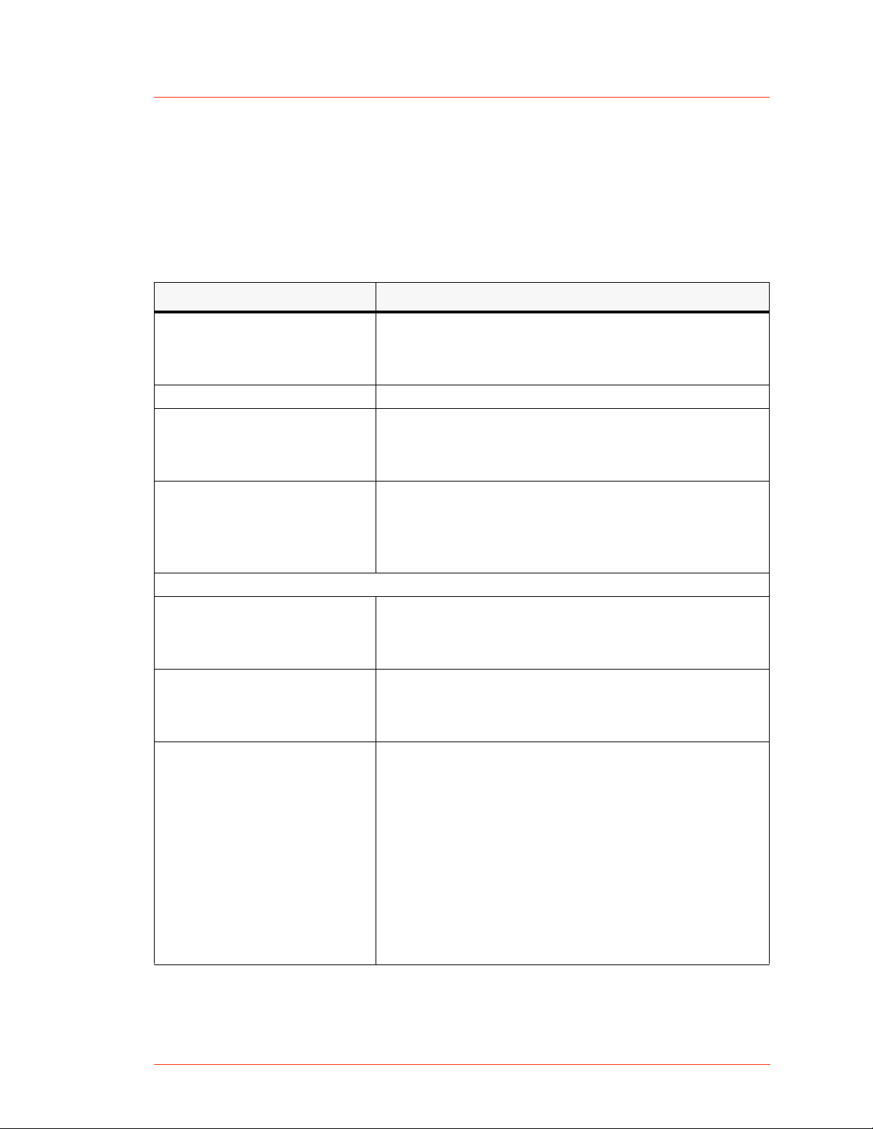
Understanding Model 1312 Options
The Model 1312 has several different unit options, each with a unique part
number and unique combination of communication interfaces. The following
table lists the option part numbers and corresponding interfaces. See also
“Rear View Drawings” on page 4-2. For specific interface information, see
“Communication Interfaces” on page 4-1.
Note: To determine which option you have, find the serial tag affixed to the
unit; the part number is on the serial tag.
Table 1-1. CESAR 1312 (E) options
Model Part
Number
61300056 X X
61300057 X X
61300058 X X
61300059 X X
61300060 X X
61300061 X X
User Port Options Host Port Options
25-pin
User Port
15-pin
User Port
RS-232 Ethernet PROFIBUS
Type Conventions
Please note the following type conventions:
• Pin and signal names appear in capitalized italics (RF POWER ON).
• New terms appear in italicized text.
• Unit labels (switches, indicators, and so on) appear in boldface text
(Mains).
• Commands (1) and command names (regulation select) appear in
boldface, lowercase text.
1-2 Safety and Product Compliance Guidelines CESAR 1312 (E)
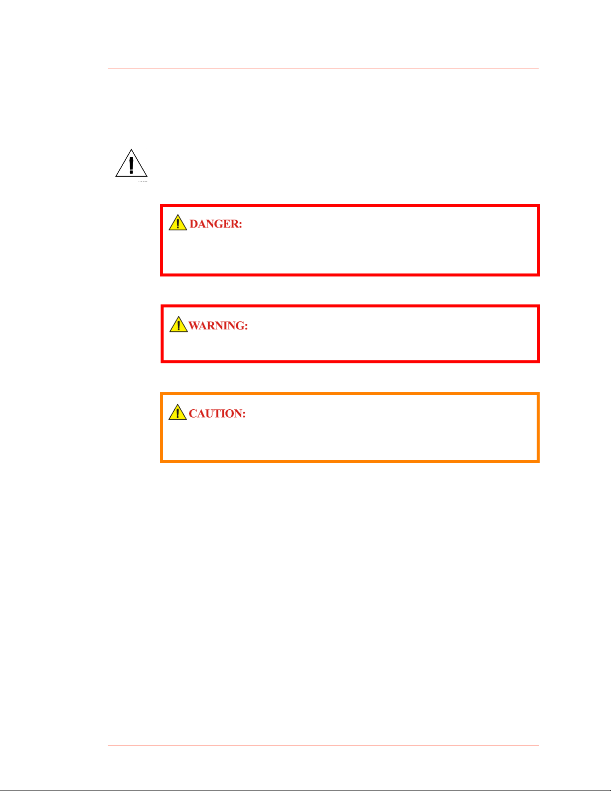
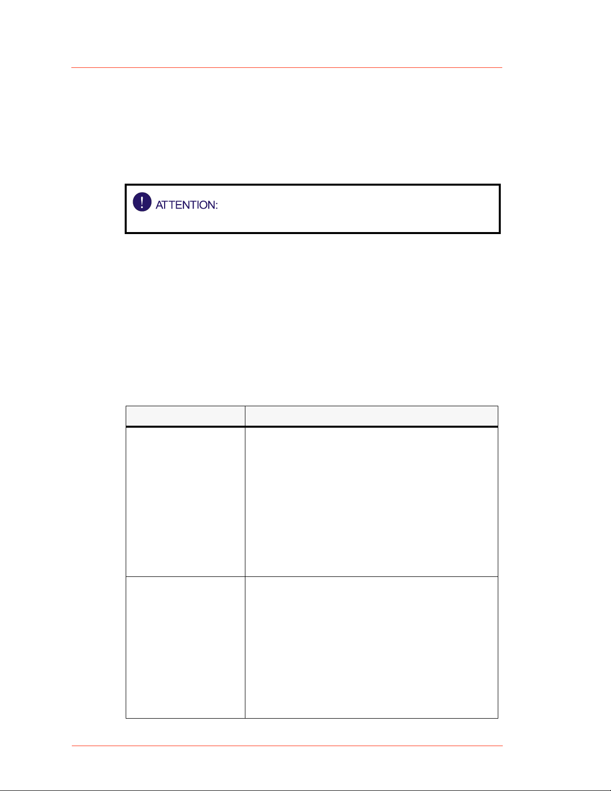
Danger, Warning, and Caution Boxes
CESAR™ 1312 Generator
This symbol represents important notes concerning potential harm to people,
this unit, or associated equipment. Dressler
symbol in Danger, Warning, and Caution boxes to identify specific levels of
hazard seriousness.
DANGER indicates an imminently hazardous situation that, if not
avoided, will result in death or serious injury. DANGER is limited to the
most extreme situations.
WARNING indicates a potentially hazardous situation that, if not avoided,
could result in death or serious injury, and/or property damage.
CAUTION indicates a potentially hazardous situation that, if not avoided,
could result in minor or moderate injury, and/or damage to property.
CAUTION is also used for property-damage-only accidents.
®
HF-Technik GmbH includes this
SAFETY GUIDELINES
Review the following information before attempting to install and operate this
unit.
Rules for Safe Installation and Operation
Please note the following:
• Do not attempt to install or operate this equipment without proper training.
• There are no user-serviceable parts inside the CESAR generator. Refer
servicing to trained service personnel (see “Customer Support” on
page 6-14).
• Ensure that this unit is properly grounded (see also “Grounding” on
page 5-4).
CESAR 1312 (E) Safety and Product Compliance Guidelines 1-3
Dressler®HF-Technik GmbH
• Ensure that all cables are properly connected (see also “CESAR
Generator User Port Options” on page 4-10 and “CESAR Generator Host
Port Options” on page 4-42).
• Verify that input line voltage and current capacity are within specifications
before turning on the power supplies (see “Electrical Specifications” on
page 3-4).
• Use proper electrostatic discharge (ESD) precautions.
• Always be careful around this equipment.
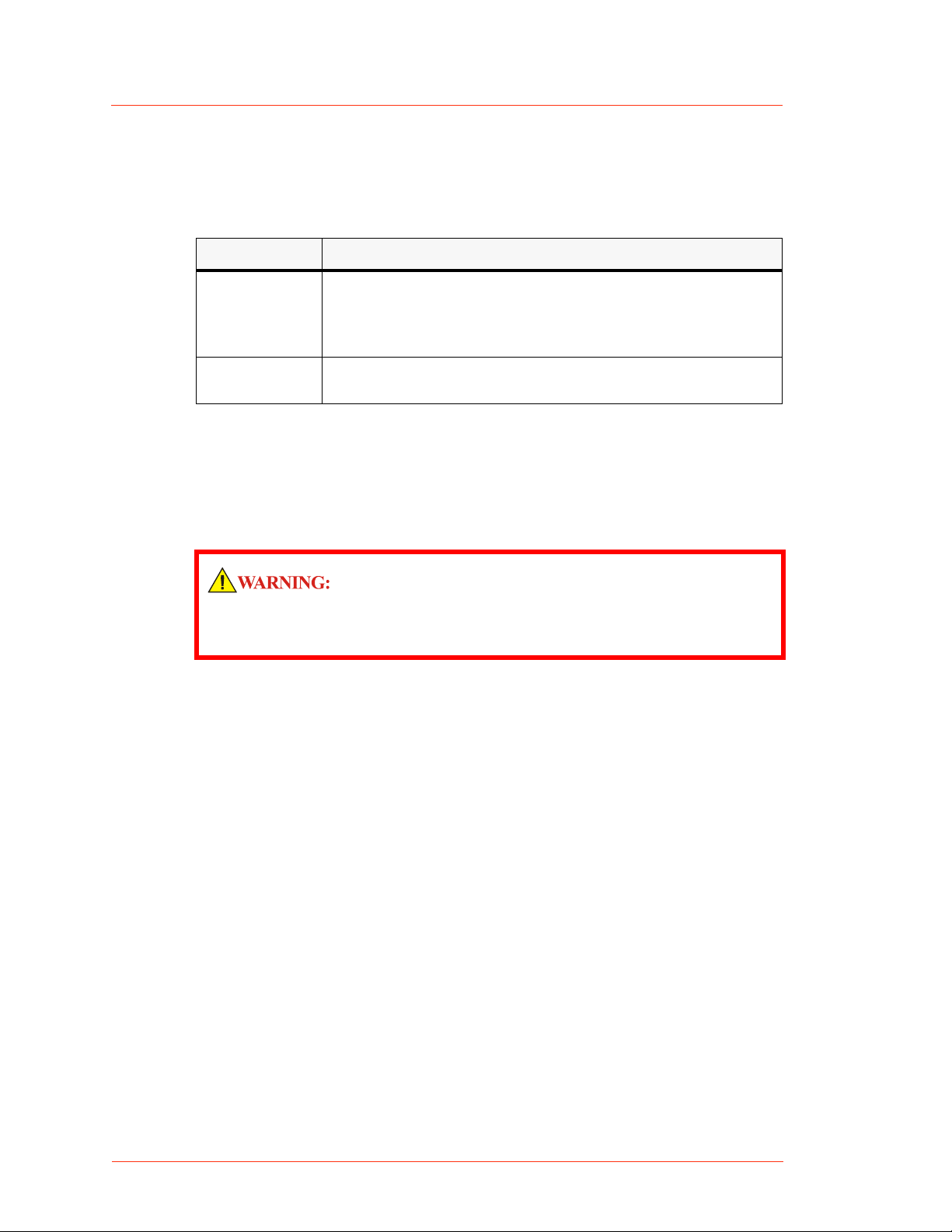
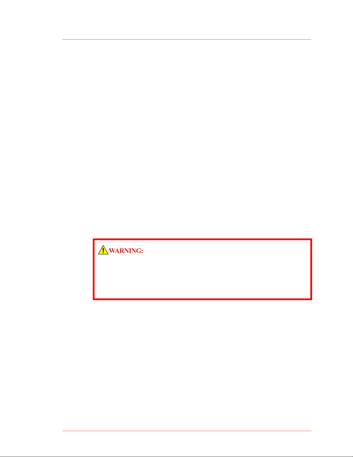
Interpreting Product Labels
The following labels may appear on the unit:
Capacitor discharge
warning
CE label
Hazardous voltage
No user-serviceable parts
inside unit
1-4 Safety and Product Compliance Guidelines CESAR 1312 (E)
CESAR™ 1312 Generator
PRODUCT COMPLIANCE
The following sections include information about unit compliance and
certification, including the conditions of use required to be in compliance with
the standards and directives.
Product Certification
Certain options of this product are certified by:
• CE marking, self addressed by Dressler Compliance Engineering
• EMC measurements, verified by Competent Body Product Services
For more information, refer to the letter of conformance (US) or declaration of
conformity (EU) accompanying the product.
Safety and Compliance Directives and Standards
Certain options of this unit have been tested for and comply with the following
electromagnetic compatibility (EMC) and safety directives and standards.
Note: This device must be installed and used only in compliance with the
directives and standards listed in addition to VDE 0113, EN 60204 (IEC
60204), and applicable requirements.
ELECTROMAGNETIC COMPATIBILITY (EMC) DIRECTIVES AND STANDARDS
Table 1-2. Electromagnetic compatibility (EMC) directives and standards
Directive Description
89/336/EEC EC Council directive on the approximation of the laws of
the Member States relating to electromagnetic
compatibility (EMC Directive)
47 CFR
Part 18
EN 55011 Limits and methods of measurement of radio disturbance
EN 61000-6-2 Electromagnetic Compatibility (generic immunity
Code of Federal Regulations—Limits and methods of
measurement of radio interference characteristics of
industrial, scientific, and medical equipment
characteristics of industrial, scientific, medical (ISM) radio
frequency equipment (Class A, Group 2) (CISPR 11)
standard— industrial)
CESAR 1312 (E) Safety and Product Compliance Guidelines 1-5
Dressler®HF-Technik GmbH
SAFETY DIRECTIVES AND STANDARDS
Table 1-3. Safety directives and standards
Directive Description
73/23/EEC EC Council directive on the harmonization of the laws of
EN 61010-1 Safety requirements for electrical equipment for
Conditions of Use
To comply with the stated directives and standards, you must meet the
following conditions of use:
the Member States relating to electrical equipment
designed for use within certain voltage limits (LVD - Low
Voltage Directive)
measurement, control, and laboratory use
RISK OF DEATH OR BODILY INJURY. Disconnect and lockout/tagout all
sources of input power before working on this unit or anything
connected to it.
• Before making any other connection to this device, connect the auxiliary
Protective Earth ground terminal to a local earth ground with a copper wire
that is sized according to the applicable requirements (see “Specifications”
on page 3-1).
• Install and operate this device in an overvoltage category II installation
only.
• Install and operate this device only in a pollution degree 2 or better
environment, which means an indoor location such as a computer room,
office, or factory floor where only nonconductive pollution occurs during
operation. Occasionally, condensation causes temporary conductivity
when the device is not operating.
• Install this device so that it is fully enclosed by a rack or other enclosure.
The rack or enclosure must be metal and either reinforced or of sufficient
thickness to resist the following tests:
A steady force of 445 N, applied through a steel hemisphere 12.7 mm
4
in diameter
An impact of 7 J applied by dropping or swinging a 0.53 kg, 50 mm
4
diameter steel sphere
1-6 Safety and Product Compliance Guidelines CESAR 1312 (E)
CESAR™ 1312 Generator
• Following the tests, there must still be a minimum clearance of 12.7 mm
between the rack or enclosure and the power supply. There shall be no
deformation of the power supply.
• You must install and operate this device with a disconnect switch that
conforms to the applicable requirements. The switch must be easily
accessible and near the device.
• The ON/OFF power switch does not completely disconnect the Mains.
You must install an external switch to completely disconnect Mains.
• Use only shielded cables on the Host (RS-232, PROFIBUS, or Ethernet)
and User Port connectors.
• Install this device so that the input power (Mains) connection is
inaccessible to the user.
• Install this device so that the output power (RF Out) connection is
inaccessible to the user.
• The AC cord must be terminated according to the applicable requirements
(see “Specifications” on page 3-1).
INTERLOCKS AND LIMITS
Dressler
limits when required by product specification. Interlocks and limits in
Dressler
safety requirements. Where interlocks or limits e xist , you mu st still mee t
and satisfy safety requirements. The presence of interlocks or limits
does not imply operator protection.
All CESAR generators have an Interlock interface. This interface allows you
to integrate any CESAR generator into a system interlock loop that can
interrupt the delivered RF power. Even if you do not connect this CESAR
generator into a larger system interlock loop, you must make the proper
interlock loop connections for the unit to enable RF power.
®
HF-Technik GmbH’s products only include interlocks and
®
HF-Technik GmbH products are not meant to meet or satisfy
CESAR 1312 (E) Safety and Product Compliance Guidelines 1-7
Dressler®HF-Technik GmbH
The CESAR Generator may be shipped with an interlock jumper plug that
provides a connection between the interlock pins. You can use this jumper
plug to satisfy the interlock and enable operation in situations where you do
not intend to connect the remaining pins on this port.
Using the interlock jumper plug disables the interlock function.
For more information on satisfying the interlock signal, see:
If you have a 25-pin User Port, see “User Port—25-Pin User Port” on
4
page 4-10.
If you have a 15-pin User Port and 9-pin Interlock connector, see “User
4
Port—15-Pin User Port” on page 4-28.
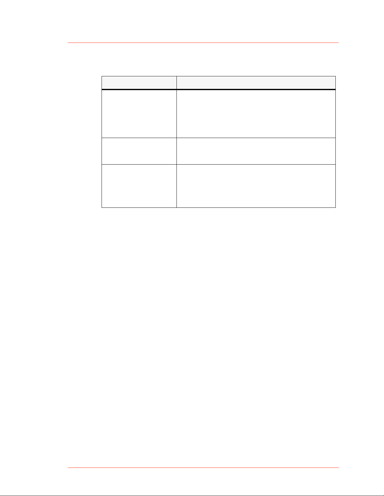
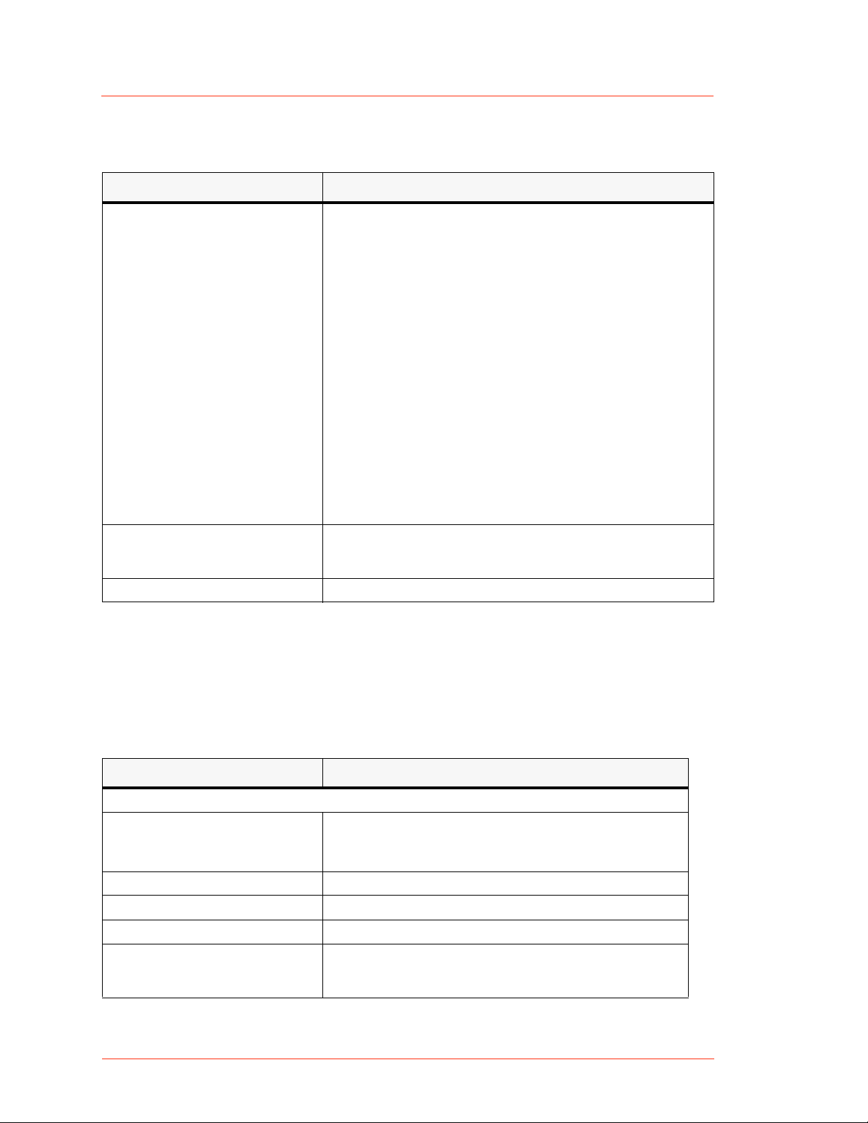
In addition, the CESAR generator includes specific limits that are described in
Table 1-4. To recover from a limiting condition, see “Troubleshooting Guide”
on page 6-2 or the specific cross-references listed in the table.
Table 1-4. CESAR generator limits
Limit Unit Response and User Resolution
RF power limit When the unit reaches the forward or reflected
power limit, the unit reduces forward power to
remain within the limits. Output is not at set point.
For more information see W11, W12, and W13 in
Table 6-2 on page 6-11.
See also pin 14 in Table 4-2 on page 4-13 or pin 5
in Table 4-4 on page 4-31, depending on which
option you have. To determine which option you
have, see “Understanding Model 1312 Options”
on page 1-2.
Overtemperature When the unit exceeds the specified maximum
temperature, RF power shuts off, and the unit
displays an error code. For information on
resolving an overtemperature condition, see E10
and E11 in Table 6-1 on page 6-8.
See also pin 22 in Table 4-2 on page 4-13 or pin 4
in Table 4-4 on page 4-31, depending on which
option you have. To determine which option you
have, see “Understanding Model 1312 Options”
on page 1-2.
1-8 Safety and Product Compliance Guidelines CESAR 1312 (E)
CESAR™ 1312 Generator
Table 1-4. CESAR generator limits
Limit Unit Response and User Resolution
Current limit When the voltage or the current exceeds the limit
of the internal SMPS, the unit reduces output to
remain within the limits. Output is not at set point.
For more information, see W10 in Table 6-2 on
page 6-11.
External pulse
frequency limit
When the external pulse frequency exceeds the
limit, the unit turns RF power off. For more
information, see W40 in Table 6-2 on page 6-11.
Target lifetime limit The target lifetime warning occurs when the
target lifetime reaches the user-set limit. This
warning does not affect the operation of the unit.
For more information, see W50 in Table 6-2 on
page 6-11.
CESAR 1312 (E) Safety and Product Compliance Guidelines 1-9

Dressler®HF-Technik GmbH
1-10 Safety and Product Compliance Guidelines CESAR 1312 (E)

CESAR™ 1312 Generator
Product Overview and Theory
DESCRIPTION
CESAR™ 1312 Generators are Class E Switched Mode Amplifiers for Radio
Frequency (CESAR), a new generation of versatile RF power supplies for
semiconductor production, and general plasma processing. This 13.56 MHz
generator employs parallel excited circuitry in a compact, 19" rack-mountable
designs. Typical applications include sputtering, reactive ion etching, RF bias,
plasma polymerization, plasma surface treatment, and CO
The CESAR generator incorporates advanced switch mode technology. This
highly efficient, resonant switching concept results in reduced energy costs,
reduced downtimes, and a longer lifetime for the unit.
laser systems.
2
Chapter
Chapter
2
Designed to regulate power into a broad range of output impedances, the
CESAR generator can operate in forward, load, or external power regulation
mode (see “Setting Regulation Mode” on page 5-15).
Both manual and automatic tuning control support operation into a fixed
impedance matching network, which simplifies system complexity, increases
reliability, and improves process-to-process repeatability (see “Controlling the
Matchbox” on page 5-20).
You can control the CESAR generator remotely through an analog User Port
(see “CESAR Generator User Port Options” on page 4-10) or a serial Host
port (see “CESAR Generator Host Port Options” on page 4-42). The front
panel features a liquid crystal display (LCD) with an easy-to-use menu that
includes widely programmable pulse functions, a target lifetime counter, and
submenus to customize your own recipes, reflected power settings, and
Variomatch settings (when the generator is connected to a Variomatch unit).
In addition, you may control RF power and match settings using the front
panel controls. For operation instructions, see “First-Time Operation” on
page 5-10 and “Normal Operation” on page 5-15.
The CESAR generator operates from a 230 VAC, 50/60 Hz power source. The
CESAR generator is air-cooled and has all power and interface-port
connections at the rear of the generator (see “Rear View Drawings” on
page 4-2).
CESAR 1312 (E) Product Overview and Theory 2-1
Dressler®HF-Technik GmbH
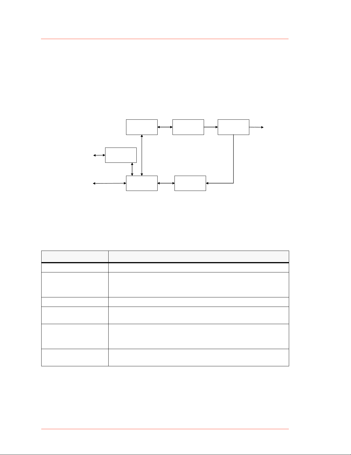
THEORY OF OPERATION
Figure 2-1 represents high-level modules of CESAR generator operation;
Table 2-1 explains each module.
User Port
Host Port
(1)
Analog I/O
(2)
Driver/Exciter
(5)
Digital
Controller
(3)
RF Amplifiers
(6)
Sensor
Electronics
(4)
RF Measure
Figure 2-1. CESAR generator block diagram
Table 2-1. CESAR generator theory of operation
Module Description
(1) Analog I/O This module provides the User interface.
(2) Driver/Exciter This module generates power at the designated output
frequency to drive the main RF sections and contains the CEX
functions.
(3) RF Amplifiers This module generates RF power.
(4) RF Measure This module samples the output signal and sends it to the
sensor electronics.
(5) Digital Controller This module is the main processor and data acquisition
section. It also provides Host communications through a Host
port.
(6) Sensor
Electronics
This module detects RF samples and sends them to the
microprocessor.
RF Output
2-2 Product Overview and Theory CESAR 1312 (E)

CESAR™ 1312 Generator
Specifications
PHYSICAL SPECIFICATIONS
The following sections describe the dimensions and physical specifications of
the CESAR generator. All generator specifications are also available online;
please visit http://www.dressler.com/products/generators.
• “Unit Dimensions” on page 3-2
• “Physical Specifications Table” on page 3-3
Chapter
Chapter
3
CESAR 1312 (E) Specifications 3-1
Dressler®HF-Technik GmbH
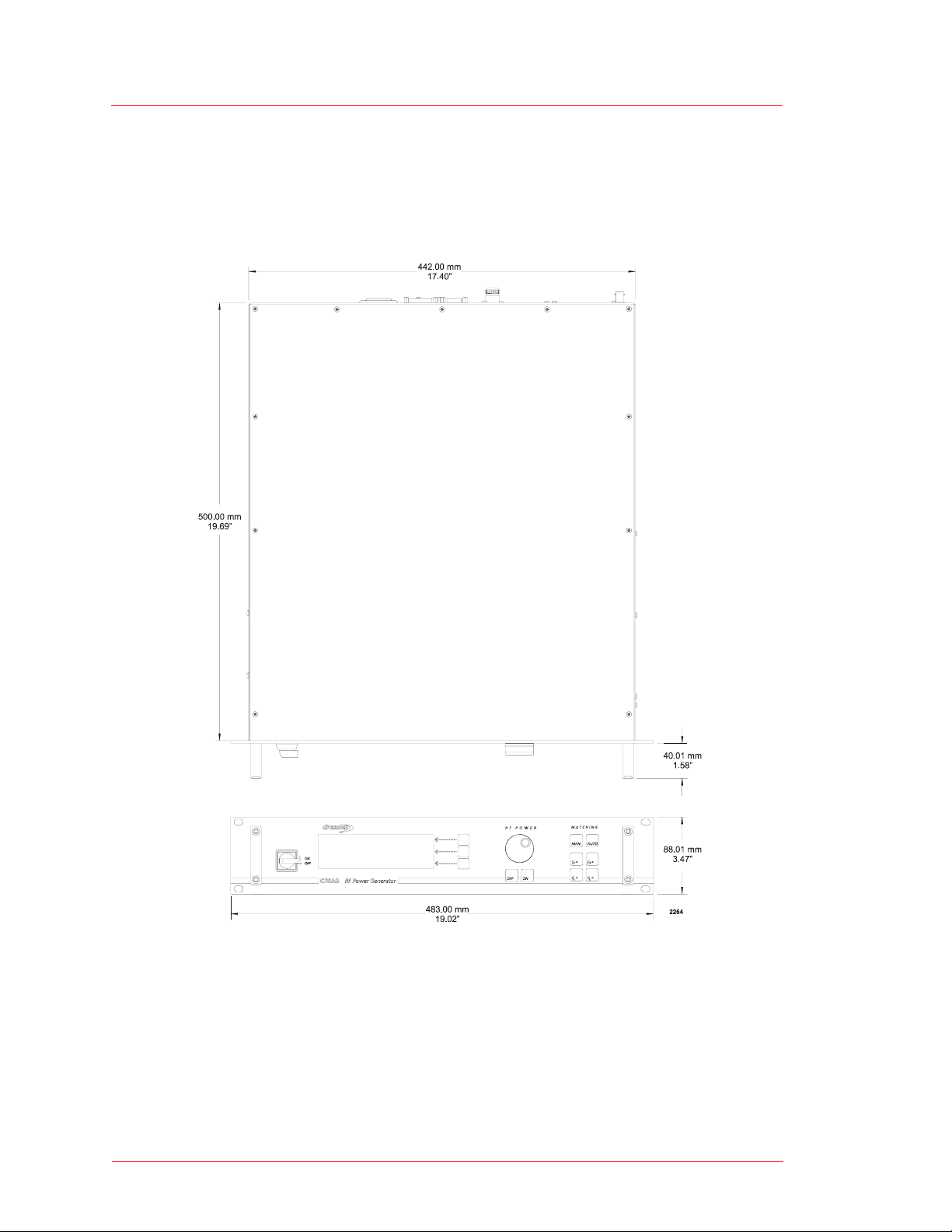
Unit Dimensions
The following illustration shows the dimensions of the CESAR generator.
Figure 3-1. CESAR Generator unit dimensions
3-2 Specifications CESAR 1312 (E)
CESAR™ 1312 Generator
Physical Specifications Table
The following table describes the physical specifications of the CESAR
generator.
Table 3-1. Physical specifications
Description Specification
Size 8.8 cm (H) x 48.26 cm (W) x 50 cm (D)
3.46" (H) x 19" (W) x 19.69" (D)
(See “Unit Dimensions” on page 3-2.)
Weight 19.2 kg 42 (lb)
Clearance 6 cm (2.36") required on each side for airflow;
10.16 cm (4
Mounting 19" rack-mounting holes are provided on the generator
front panel.
″ ) required at rear for cable connections
For more information, see “Mounting the CESAR
Generator” on page 5-3
Connector/Cable specifications
AC input power IEC 320 connector
For more information, see “Connecting AC Input
(Mains) Power” on page 5-8.
RF output N-Type, female connector
For more information, see “Connecting RF Output
Power” on page 5-4.
User Port (Analog I/O) There are two analog interface options available for
the CESAR generator:
•A 25-pin User Port (see “User Port—25-Pin User
Port” on page 4-10)
•A 15-pin User Port (see “User Port—15-Pin User
Port” on page 4-28).
To determine which analog interface you have, see
“Understanding Model 1312 Options” on page 1-2. For
more information on the analog interfaces, see
“CESAR Generator User Port Options” on page 4-10.
CESAR 1312 (E) Specifications 3-3
Dressler®HF-Technik GmbH
Table 3-1. Physical specifications (Continued)
Description Specification
Host Port The CESAR generator has three host port
communication interface options:
•An RS-232, 9-pin, female, shielded, subminiature-
D connector (see also “Host Port—RS-232 With
AE Bus” on page 4-43)
•A PROFIBUS 9-pin, female, subminiature-D
connector (see also“Host Port—PROFIBUS” on
page 4-50)
•An Ethernet Modbus/TCP connection (see also
“Host Port—Ethernet (Modbus/TCP)” on
page 4-56)
To determine which host port you have, see
“Understanding Model 1312 Options” on page 1-2. For
more information on the Host port options, see
“CESAR Generator Host Port Options” on page 4-42.
CEX CEX BNC, female
Front panel display LCD graphic display
ELECTRICAL SPECIFICATIONS
Table 3-2 describes the electrical specifications of the CESAR generator.
Table 3-2. Electrical specifications
Description Specification
Input power specifications
Line voltage 230 VAC (187 VAC to 253 VAC), 1 φ with ground
(PE)
Line Frequency 50/60 Hz
Line current 8 A nominal line, full power
Input power 1780 VA
Power factor 97% to 99%
3-4 Specifications CESAR 1312 (E)
 Loading...