

Dresser RCS Instructions Manual
r
ROOTS
$2.00
INSTRUCTIONS
CONTENTS
INFORMATION SUMMARY
...
Receiving
OPERATING CHARACTERiSTiCS
Description
OPERATING LIMITATIONS
Pressure
INSTALLATION. . . . . . . . . . . . . . . . . . . . . . . . . .
Mounting
LUBRICATION
Oil System
DO
THESE
Installing
...
Control
...
Temperature
...
Aligning
.............................
...
Sealing
THINGS
NUMBERS
...........
...
Operating
.............
...
Protection
..................
...
Speed
...
Piping
...
Servicing
....
IN
( )
This page
To
ARE
2
2
..
3
6
Get
ROTARY
METRIC
The
EQUIVALENTS
OPERATION
Starting
TROUBLE
Capacity
SAFETY PREACUTIONS. . . . . . . . . . . . . . . . . . .
Physical
MAINTENANCE/REPLACEMENTS
Servicing
PARTS
DISTRIBUTORS
Most
...............................
...
Checking
SHOOTING
...
Power
...
Operating
...
Repairs
DRAWiNGS
............................
From
LOBE
...
.......................
...
...
.........................
Your
BLOWERS
Running
Heating
...
General
Clearances
Roots
............
Blower
..
6
7
8
8
13
20
IICheck
claim with carrier, notify nearest
ElUnpack
against
shortage appears.
BlStore
tion, if possible. Lift
sTALLATION
ment. Keep covers on all openings. Protect against
weather
tions in
supervision
nearest Dresser
weeks in advance
Standard
IDProvide
persons working on or near equipment during
stallation
shipment for damage in transit. After filing
Sales Office or factory.
shipment carefully
Packing List. Notify Sales Office or factory if a
in a clean,
and
corrosion
LIMITATIONS
this
manual and plan
by
charges
for adequate safeguards against accidents
and
NOTE - Information In this manual is correct as
without
dry
location until ready for
by
methods discussed under IN-
to
avoid straining or distorting
if
outdoor storage is necessary.
a Service Engineer is needed, contact
Parts
and
and
confirm
will
be made.
operation. See PRECAUTIONS.
obligation to make similar changes on equipment
and
check contents
and
INSTALLATION sec-
the
complete installation.
Service Center
by
your purchase order.
of
the date
the
at
least two
of
publication. The Manufacturer reserves the right to make design or material changes without notice,
installa~
equip-
the
both
in-
of
prior manufacture.
If
to
iii
Install all equipment correctly. Foundation design
must
be adequate
mended accessories for operating protection.
IiIMake
rectly lubricated before start-up. See LUBRICATION.
'::1 Read
equipment briefly to check for obvious faults, and make
corrections. Follow with a trial
operating conditions.
mIn
tion of a new unit, do not
Sales Office or factory, giving all nameplate information
plus
of
the
EUnits
the
the
Parts. Good inspection
reduce
page for
sure
starting
the event of trouble during installation or opera-
an
outline of operating conditions
trouble.
out
owner.
It
operations described in this manual, using Factory
the
parts
and
piping carefully done. Use recom-
both
driving and driven equipment is cor-
check points under OPERATION. Run
run
under normal
attempt
of warranty may be repaired or adjusted
is recommended
and
maintenance practices should
need for repairs. See Distributor List on
and
service after warranty period.
repairs. Notify nearest
and
a description
that
such work be limited
Bulletin IRB-115-387
by
to
last
and
OPERATING
Roots RCS blowers,
available
Within
produce reasonable
units
handling
are
not
displacement
mined
employs
shafts
cylinder closed
rotate,
out
The
resistance
Effective sealing of
discharge
operating
tacts
Clearance
tained
mounted
casing.
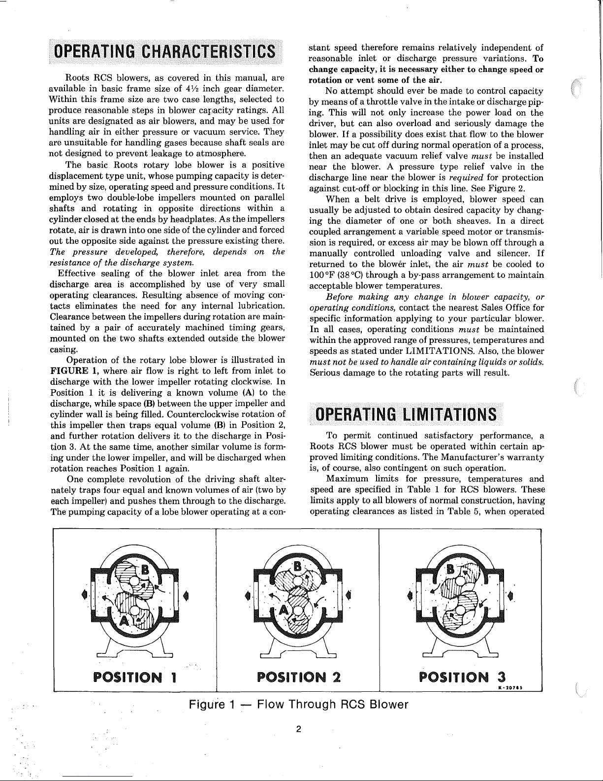
FIGURE
discharge
Position 1
discharge, while
cylinder wall is
this
and
tion
ing
rotation
nately
each impeller)
The
in
basic frame
this
frame
are
designated
air
in
unsuitable
designed
The
by
air
the
pressure
eliminates
by a pair
Operation
impeller
further
3.
At
under
One complete revolution of
traps
pumping
for
to
basic
type
size,
operating
two
double-lobe impellers
and
rotating
at
is
drawn
opposite side
of
the
area
clearances.
between
on
the
of
1,
where
with
it
is delivering a known volume
then
rotation
the
same
the
lower impeller,
reaches
four
and
capacity
CHARACTERISTICS
size are two case lengths, selected
steps
as
either
handling
prevent
Roots
unit,
the
ends
into
against
developed, therefore, depends on
discharge
is accomplished
Resulting
the
need for
the
of
accurately
two
shafts
the
rotary
air
the
lower impeller
space
being
filled. Counterclockwise
traps
delivers
time,
Position
equal
pushes
as
covered
size of
in
blower carJacity
air
blowers,
pressure
gases
leakage
rotary
whose
speed
in
opposite directions within a
by
headplates.
one side of
the
system.
the
blower inlet
impellers
extended
lobe blower is
flow is
(B)
between
equal volume
another
and
1 again.
and
known volumes of air (two
them
of a lobe blower
in
this
manual,
4Y2
inch
gear
diameter.
ratings.
and
may
be
or
vacuum
because
to
atmosphere.
lobe blower is a positive
pumping
and
pressure
the
pressure
by
absence of moving con-
any
during
machined
right
rotating
the
it
to
the
similar volume is form-
will
the
through
service.
shaft
capacity
conditions.
mounted
cylinder
use of
internal
outside
to
upper
be
driving
operating
on parallel
As
the
impellers
and
existing
area
from
very
lubrication.
rotation
left from
(B)
discharge in Posi-
discharged
timing
the
illustrated
clockwise.
(A)
impeller
rotation
in Position
shaft
to
the
discharge.
are main-
are
to
All
used
for
They
seals are
is deter-
It
forced
there.
the
the
small
gears,
blower
in
inlet
to
In
to
the
and
of
2,
when
alter-
by
at
a con-
stant
speed
therefore remains relatively
reasonable inlet or discharge
change
rotation
by
ing.
driver,
blower.
inlet
then
near
discharge line
against
usually
ing
coupled
sion is required, or excess air
manually
returned
100
acceptable blower
operating conditions,
specific information
In
within
speeds
must
Serious
Roots
proved
is, of course, also
speed
limits
operating
capacity,
or
attempt
No
means
of a
This
but
If
may
be
an
adequate
the
cut-off
When
be
the
diameter
arrangement
to
OF
(38°C)
Before
all cases,
the
as
not
be
damage
OPERATING
To
permit
RCS blower
limiting conditions.
Maximum
are
apply
it
is
necessary
vent
some
of
should ever be
throttle
will
can
a possibility does
cut
blower. A
a belt drive is employed, blower speed can
adjusted
controlled unloading valve
the
through
making
operating
approved
stated
used
valve in
not
only increase
also overload
off
during
vacuum
pressure
near
the
blower is required for protection
or
blocking
to
obtain
of one
a variable speed
blower inlet,
a by-pass
temperatures.
any
contact
applying
conditions
range
under
LIMITATIONS.
to handle air
to
the
rotating
LIMITATIONS
continued
must
contingent
limits for pressure,
specified
to
clearances
in
Table 1 for RCS blowers. These
all blowers of
as
listed
the
air.
exist
normal operation of a process,
relief valve
in
or
may
change in blower capacity, or
of
pressures,
satisfactory
be
operated
The
on
normal
pressure
either
to
change
made
to
control
the
intake
or
the
power load on
and
seriously
that
flow
must
type
relief valve
this
line. See
desired
both
the
the
to
containing
in
capacity
sheaves.
motor
be blown off
and
air
must
arrangement
nearest
your
particular
must
temperatures
Also,
liquids or solids.
parts
will result.
performance, a
within certain ap-
Manufacturer's
such
operation.
temperatures
construction,
Table
5,
independent
variations.
discharge pip-
damage
to
the
be
Figure
by
In
or transmis-
through
silencer.
be cooled
to
Sales Office for
be
maintained
the
when operated
of
To
speed or
capacity
the
the
blower
installed
in
the
2.
dhang-
a direct
If
to
maintain
blower.
and
blower
warranty
and
having
a
POSITION 1 POSITION 2 POSITION 3
Figure 1 :-Flow Through ReS Blower
•
K
~207'J
2
l,
under
standard
one
of
these
Example:
rise (increase
discharge) for
its
maximum
can
easily occur
Temperature rise then is the
words,
the
imum
rating
pressure,
Be sure to
and
mercury
the
inlet
along
with
operating
of
PRESSURE-On
(between blower
figure
listed
in
Also,
pressure
never
exceed 25
size.
On
vacuum
mospheric
be
greater
TEMPERATURE-RCS
proved only for
ture
limitations
A.
Measured
when
considered as
around
unless
B.
If
inlet
allowable
% of
the
temperature
C.
An average
to
250°F.
SPEED
speeds
be direct coupled to
pressure/temperature
low speeds, excessive
factor as
up
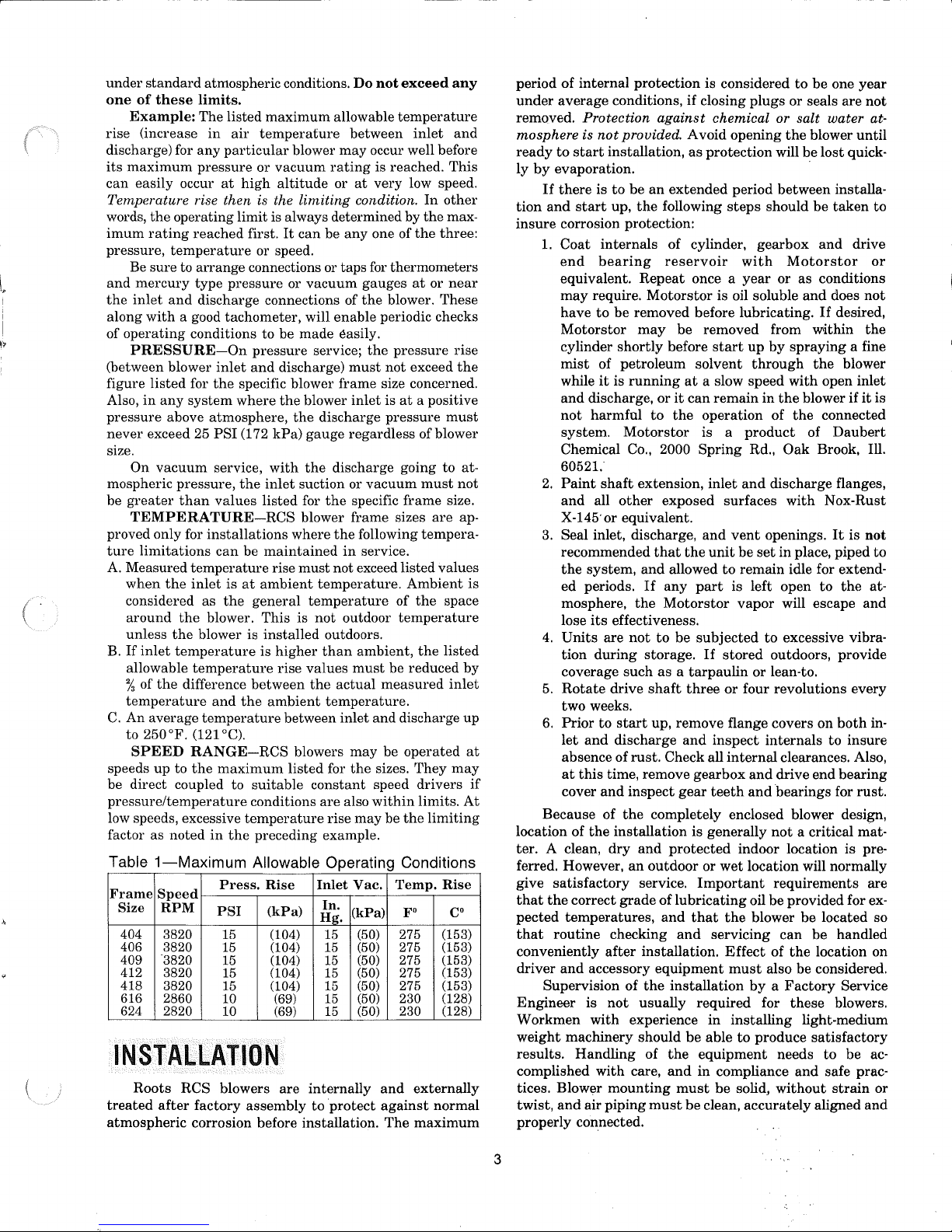
Table
1-Maximum
Frame
Speed
Size
404
406
409
412 3820
418 3820
616
624
atmospheric conditions.
limits.
The listed
in
any
pressure
operating limit is always determined by
reached
temperature
arrange
type
and
discharge connections of
a good tachometer, will enable periodic checks
conditions to be made easily.
inlet
for
the
any
system
above atmosphere,
PSI
service,
pressure,
than
values
installations
can
temperature
the
inlet
the
blower.
the
blower is
temperature
temperature
difference
and
temperature
(121°C).
RANGE-RCS
to
the
maximum
noted
in
maximum
ail'
temperature
particular
or
vacuum
at
high
altitude
first.
or speed.
connections or taps for thermometers
pressure
pressure
and
discharge)
specific blower frame size concerned.
where
the
(172
kPa)
with
the
inlet
listed
be
maintained
rise
is
at
ambient
the
general
This
installed
is
higher
rise
between
the
ambient
suitable
conditions
temperature
the
preceding example.
Allowable Operating Conditions
Press.
Rise
RPM
3820
3820
'3820
2860 10
2820
PSI
15
15
15
15
15
10
(kPa)
(104)
(104)
(104)
(104)
(104)
(69)
(69)
INSTALLATION
Roots
treated
atmospheric
RCS blowers are
after
factory
corrosion before installation. The
assembly
Do
not
allowable
between
blower
may
occur well before
rating
is reached.
or
at
very low speed.
limiting
It
can
or
vacuum
blower
the
gauge
the
suction or
for
blower frame sizes
where
must
temperature
is
values
the
between
blowers
listed for
internally
condition.
be
anyone
gauges
the
service;
discharge
temperature.
not
constant
are
Inlet
Hg.
to
the
must
inlet
regardless of blower
discharge going to at-
vacuum
the
specific
the
following tempera-
in
service.
not
exceed listed values
outdoor
outdoors.
than
ambient,
must
actual
measured
temperature.
inlet
and discharge
may
the
sizes. They
speed drivers
also
within
rise
may
Vac.
In.
(kPa)
(50)
15
(50)
15
(50)
15
(50)
15
(50)
15
(50)
15
(50)
15
and
protect
against
exceed
temperature
of
blower. These
pressure
not
is
at
pressure
frame
of
temperature
be reduced
be
operated
be
the
Temp.
FO
275
275
275
275
275
230
230
any
inlet
and
This
In
other
the
max-
the
three:
at
or neal'
rise
exceed
Ambient
the
a positive
must
must
not
size.
are
the
space
the
listed
inlet
may
limits.
limiting
Rise
Co
(153)
(153)
(153)
(153)
(153)
(128)
(128)
externally
normal
maximum
ap-
is
by
up
at
if
At
period
of
internal
under
average
removed. Protection
mosphere is
ready
to
start
ly
by
evaporation. .
If
there
tion
and
start
insure
corrosion protection:
1.
Coat
end
equivalent.
may
have
Motorstor
cylinder
mist
while
and
not
system.
Chemical Co., 2000
60521.
2.
Paint
and
X-145'or equivalent.
3.
Seal inlet, discharge,
recommended
the
system,
ed periods.
mosphere,
lose
4.
Units
tion
coverage
5.
Rotate
two weeks.
6.
Prior
let
and
absence
at
this
cover
Because of
location of
ter. A clean,
ferred. However,
give
satisfactory
that
the
correct
pected
that
conveniently
driver
Engineer
Workmen
weight
results.
complished
tices. Blower
twist,
properly
temperatures,
routine
and
Supervision of
is
machinery should
Handling
and
air piping
connected.
protection
conditions, if closing
against
not
provided. Avoid opening
installation,
is
to
be
an
up,
the
internals
bearing
Repeat
require.
to
of
it
discharge,
harmful
all
its
during
to
the
accessory
with
with
Motorstor
be
removed before lubricating.
may
shortly
petroleum
is
running
or
to
Motorstor
shaft
extension,
other
that
and
If
the
effectiveness.
are
not
to
storage.
such
as a tarpaulin
drive
shaft
start
up, remove flange covers on
discharge
of
rust.
time, remove
and
inspect
the
completely enclosed blower design,
installation
dry
and
an
outdoor
service.
grade
checking
after
installation.
equipment
the
not
usually
experience
of
care,
mounting
must
is considered
chemical or salt water at-
as
protection
extended
following
of cylinder,
reservoir
once a
be removed from within
before
start
solvent
at
a slow
it
can
remain
the
operation of
is a
Spring
inlet
exposed surfaces
and
the
unit
allowed
any
part
Motorstor
be
subjected
If
three
and
inspect
Check all
gearbox
gear
teeth
is generally
protected
or
Important
of
lubricating
and
that
and
servicing
installation
required for
in
be
able
the
equipment
and
in
must
be
clean,
is oil soluble
to
stored
wet
compliance
be
to
be
one
year
plugs
or seals are
the
blower
until
will be
lost
quick-
period between installa-
steps
should
gearbox
with
year
up
through
speed
in
product
Rd.,
and
vent
openings.
be
set
remain idle for extend-
is left open
vapor
to
or
or
four revolutions every
internals
internal
and
and
indoor location is pre-
location will normally
oil be provided for ex-
the
blower
Effect
must
also be considered.
by a Factory
installing
to
produce
solid,
accurately
be
taken
and
drive
Motorstor
or
as
conditions
and
does
If
desired,
by
spraying
with
the
blower if
the
Oak
discharge flanges,
with
in
place, piped
will escape
excessive vibraoutdoors, provide
lean-to.
clearances. Also,
drive end
bearings
not
a critical mat-
requirements
be
can
of
the
these
light-medium
needs
and
without
a fine
the
blower
open inlet
connected
of
Daubert
Brook, Ill.
Nox-Rust
It
is
to
the
both
to
insure
bearing
for
rust.
located so
be
handled
location on
Service
blowers.
satisfactory
to
be
safe prac-
strain
aligned
not
to
or
not
the
it
is
not
to
at-
and
in-
are
ac-
or
and
3
Two
methods
base. One is
headplates.
tapping
cable pull
eyebolts
under
method
drive
with
on
are
the
prevents
shaft.
When
with
or
without
under
the
base
that
no
strains
ing
feet,
or
use
NOT
the
Before
may
be
to
use
eyebolts screwed
Test
them
first
a hammer.
these
bolts
not
available, lifting slings
cylinder
adjacent
strain
blower is furnished
a driver, use of lifting slings
flanges is required.
are placed on
on
any
mounted
eyebolts
starting
in
the
installation, remove plugs, covers
or seals from blower inlet
inspect
If
headplates
vent
shaft
at
flanges
this
again
ing.
be
disappear
pay
is especially
nished
may
concrete
tory
leveling
the
interior completely for
cleaning is required, finish
and
impeller
such
as
DuPont
by
hand
all points.
and
drive
time
with
to
keep
Washing
clean.
out
The
during
Care,
plus
dividends when
true
without
be
to
mount
pad,
results.
Direct
and
alignment.
use
of
It
Triclene D.
to
make
sure
Anti-rust
shaft
extension
the
same
out
dirt
until
is
not
required if
corrosion inhibitor
operation.
consideration of all possible problems, will
arranging
when
a baseplate.
such a unit
but
this
generally produces
definitely causes
structural
recommended mounting.
must
be
rigidly reinforced when
spring
transmission
sulating
should
structure,
to
well anchored
mounting
plate
surface machined flat,
ing
mounted.
holes located
alternative, smaller
be used.
more difficult,
blower.
carry
For
should
areas
type
mountings
can
usually
pad 1 to
be
supported
with
the
a blower
plate
2 inches
by
a rigid concrete slab laid on
blower
and
without
and
carefully leveled steel or
be
provided
be
about
1 inch
and
at
one side
It
should
to
and
have
match
plates
This
is more complicated usually
and
can
Use
of a
high
quality
tant.
With
the
mounting
blower on
it
without
bolting
used
to
handle a blower
into
the
for
tightness
In
lifting, keep
as
nearly vertical
and
fractures
the
direction of
as
may
to
the
headplates.
being
placed on
mounted
Arrange
the
blower
the
on a baseplate,
these
casing
accessory equipment. DO
the
top
of
the
headplates.
and
discharge connections
dirt
or foreign material.
by
thoroughly
After
that
the
compound
may
solvent.
ready
the
the
blower is a
The
washing
with a petroleum
impellers
Then
to
the
used
blower mounting.
convenient procedure
the
this,
turn
on
the
also be removed
cover
connect
interior is found
will vaporize
"bare"
directly on a floor
least
the
most
problems in
framing members is also
If
unavoidable,
part
should
be
reduced
(25
to 50 mm) thick.
a full steel
not
plate
the
of a building,
be used. Noise
by
use of a cork in-
attached
top
driver.
base,
it
is recommended
at
the
installation point. The
(25
mm) thick,
large enough
one
end
properly sized
the
blower foot drilling.
at
each
end
to
after
of
studs
the
provide level-
the
makes
produce
plate
twist
or
machinist's
in
place
and
and
check for rocking.
strains
level is impor-
leveled,
without
top
of
the
by
possible.
be
passed
Either
extended
passing
slings so
or mount-
and
cylinder,
sol-
the
drive
turn
freely
connection
the
flanges
the
air pip-
and
This
unit, fur-
or
small
satisfac-
not
members
and
The
pad
to
the
of
the
cork
that
cast
iron
with
its
top
blower is
or
tapped
As
blower
may
leveling
in
the
set
the
If
it
If
at
to
an
is
not
solid,
determine
under
one foot
each of
mounting
sure
direct
the
accurately
the
while
thickness.
final
the
diagonally-opposite
studs
the
impellers still
coupled
motor
shaft
with
blower
the
driver is on
This
shaft
alignment
When
blower
to
on a common baseplate,
perly
aligned
poses.
the
baseplate
vibration,
directions so
vided
under
ly
leveled
It
twisted
alignment.
after
the
nect
the
should
and
Satisfactory
and
that
with
suitable anchor bolts.
and
partly
by
shimming, is recommended.
is
possible
during
For
base
drive
turn
freely
hold-down screws
ly
in
and
contact
again
with
check for free impeller rotation. Finally, if
blower is direct coupled to
coupling
alignment
the
total
thickness of
to
stop
the
rocking. Place half of
short
or
screws.
to
a driving motor, consider
and
the
be
bolted
allows
and
is to
installation
on a concrete slab
leveling
it
inside
for a
shipment,
this
has
been leveled
and
at
and
the
Rotate
turn
the
necessity
blower shaft.
directly
shims
freely.
of
at
the
for
Best
to
adjustment
by
varying
driver
the
be
treated
the
have
been factory
assembly
as a unit
can
be
that
the
top
of
the
is free of twist. The slab
the
base,
after
base-mounted
thus
disturbing
reason,
rotate
all points.
determine
base.
carefully
the
If
make
and
blower
not,
the
and
Loosen
whether
insert
driver, check
make
feet,
If
it
the
least
of
shim
base
The
assembly
the
bolted down. Discon-
rections.
In
blower, consider how
the
blower design
sible rotation.
a
Standard
shaft
has
the
When
the
driver
exceed
LIMITATIONS
sizes. A
connect
a
Coupling halves
sufficient
strains
planning
at
the
drive
the
flexible
the
and
the
installation,
piping
and
assembly. RCS blowers have rever-
arrangement
top. Horizontal
shaft
at
a blower is
RPM
maximum
DIRECT
must
be selected or governed so
speed
the
left.
and
arrangements
on vertical
units'
standard
COUPLED
rating
of
the
for allowable speeds for various blower
type
coupling should always be
driver
and
gap
between
end
thrust
blower
must
be
shaft
on
shafts.
accurately
ends
provided so
either
shaft
minimized. This will require considerable care in
mounting
perfect
must
trical center if end
recommended. Coupling halves
shafts
them.
shafts
reading,
of
the
driver.
The
alignment in all directions
be
established
The
following
so
Maximum
should
taken
that
with
play
exists.
requirements
only
light
deviation
not
exceed .005" (.13 mm)
on
the
two coupling hubs.
two
shafts
as
possible,
the
motor
armature
for a good installation are
must
tapping
in
is required
offset
shims
required
this
under
and
tighten
drive
shaft
to
make
the
blower is
the
to
be aligned very
arrangement
mounting
1/8
motor
to
height
is for
plate
inch
(3
mm)
position in
thicknesses.
mounted
will have been pro-
for leveliIJ.g pur-
obtained
is rigid
by
and
setting
free of
carefully in two
must
be pro-
use of
it
has
following
shaft
grouting
been careful-
to become
the
by
hand.
the
blower foot
original
checks
all feet are even-
shims as required
shaft
and
any
necessary cor-
before
units
are
has
setting
dictated
the
drive
arrangement
to
its
driver,
as
not
blower. Refer
used
aligned, and a
that
side
are
avoided or
must
be
in
as near
and
the
gap
on
its
elec-
be,
fitted
to
the
two
to
install
alignment
total
Maximum
of
indicator
devia-
the
be
of
It
the
by
to
to
to
the
the
4
tion from parallel of
exceed .001"
the
coupling.
(.03
When a blower is
tion of sheave diameters will
the
inside coupling faces should
mm) when checked
BELT
DRIVEN,
result
at
six points around
the
proper selec-
in
the
required blower
not
speed. This flexibility can lead to operating temperature
problems caused
sure
the
drive speed selected is within
for
the
specific blower size, as specified under LIMITA-
by
blower speed being too low. Make
the
allowable range
TIONS.
Belt
drive arrangements usually employ two or more
V-belts running
driver is less critical
must
be level
driver should be mounted on
blower (horizontal piping)
shaft
on a horizontal blower. The driver
mounted on
justing
and
correctly,
and
the
nominal
lengths to
Install
not
more
The
shaft
ed into place
driving fit can damage a bearing,
blower damage
operating position. A loose fit
vibration,
The driver sheave should also be mounted as close
its
bearing as possible,
rectly. Position
of
the
total
from
the
blower,
of
the
sheave is accurately in line with the blower sheave.
This position minimizes belt wear,
adjustment
After belts are installed,
dance with
ly enough tension should be applied to
when
the
in
grooved sheaves. Installation of
than
for direct coupling,
and
parallel with
and
an
adjustable
removing
both
sheaves need to be mounted on their
be
used.
the
blower sheave so
than
shaft
Ya
inch
the
V-belts. To position
center distance known for
(.3
mm) from
fit should be such
by
hand
or
by
the
the
inlet side of a vertical
on tlie side nearest to
base to permit installig, ad-
that
its
the
that
the
sheave can be work-
very light tapping. A
and
by
and
may
the
forcing
result
driver on
the
impeller
or
wobbly sheave will cause
in
shaft
and
again should fit
its
adjustable base so
breakage. "
but
its
blower shaft. The
must
also be
the
shafts
the
inner
hub
face is
drive end cover.
tight
may
cause internal
out
of
its
normal
the
shaft
movement is available in the direction away
and
mount
the assembly so
and
for
both
installing
the
manufacturer's instructions. However,
adjust
and
tightening
their tension in accor-
blower is operating under load.
that
the
allows sufficient
the
prevent
slippage
Excessive
the
shaft
the
driver
belt
or
to
cor-
that
face
belts.
on-
tightening can lead to early bearing failures.
In
the
absence of belt manufacturer's instructions for
tensioning,
1.
2.
3.
the
following procedure may be used.
With
the
belts loose, pull the slack on all of
the
bottom
Adjust
motor position
appear to be
Thump
tighten
the
them
side of
belts with your fist.
the
seating
drive.
to
tighten belts until
in
the
sheave grooves.
If
more until they vibrate
them
to
they
they feel dead,
and
feel
springy when struck.
4.
Run-in
the
While running
appears in
5.
Stop
dividual belts
hand
deflect each belt only
face is even with
the
blower
the
motor
on
the
drive for a
as
instructed
adjust
the
slack side of
and
compare the tensions of
by
pressing down firmly with one
top surface.
short
period, after preparing
in a following paragraph.
until only a very
the
belts.
It
should be possible to
to
the
point where
the
bottom of the other
slight
its
the
top
bow
in-
sur-
underdeflected belts.
6.
A new
set
of belts should be first tensioned about
Va
greater
wear-in. Before
operation, increase
than
normal
putting
to
allow for
the
drive into normal
the
tension as obtained above
by a small amount. Recheck after each 8 hour
operating period during
just
as
necessary.
Before operating
the
the
first 50 hours and, ad-
drive under power to check initial belt tension, first remove covers from
nections. Make sure
the
shaft
by hand. Place a coarse screen over
nection to
while
prevent
it
is operating,
discharge opening.
under
LUBRICATION.
Before connecting
the
interior is still clean,
anything being sucked into the blower
and
avoid
Put
oil
in
the
PIPING,
standing
sumps per instructions
remove
in line with
anti-rust compound from blower connections. Pipe used
than
these
should be no smaller
connections,
new piping throughout is strongly recommended.
tion, make sure
beads, or foreign materials of
against
filter is
damage to
not
backed with hardware cloth
tions. Make provisions
debris after a few hours' operation.
when
its
usefulness
deteriorate
it
is free of dirt, scale, cuttings, weld
any
kind. To further
the
blower, especially when an inlet
used, install a
and
small pieces going into the blower may
has
substantial
at
to
clean
ended,
as
screen of
or
near
the
this
screen of collected
It
should be removed
the
wire will eventually
cause serious damage.
Pipe flanges or male
connections accurately
correct misalignment
%
In
most
cases this will
impeller rubbing.
or
result
in a broken drive shaft.
ing should be supported near
In
threads
and
by
springing or cramping
distort
severe cases
must
squarely. DO NOT
the
blower casing
it
can prevent operation
For
the
blower
meet the blower
similar reasons, pip-
to
weight strains. Also, if pipe expansion is likely to occur
from temperature change, installation of flexible
tors
or expansion joints is advisable.
in
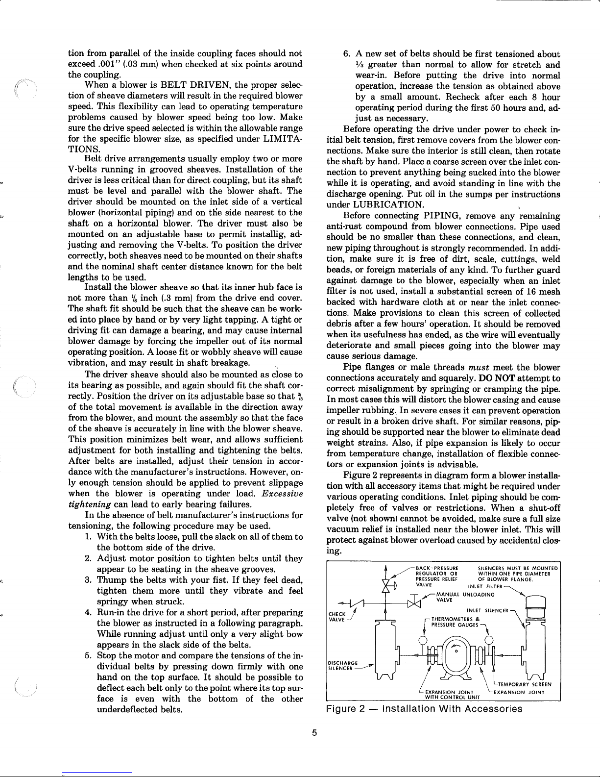
Figure 2 represents
tion with all accessory items
various operating conditions.
diagram form a blower installa-
that
might
be required under
Inlet
piping should be completely free of valves or restrictions. When a shut-off
valve (not shown)
vacuum relief is installed near
protect
against blower overload caused
cannot
be avoided, make sure a full size
the
blower inlet. This will
by
ing.
~-i----~Cl
CHECK
I
VALVEJ
Figure 2 -
BACK-PRESSURE
REGULATOR
~
PRESSURE
VALVE
~MANUAL
r
Installation
ReliEF
VALVE
THERMOMETERS
PRESSURE
With
SILENCERS
OR
WITHIN
OF
BLOWER
INLET
FILTER
UNLOADING
INLET
SILENCER
&
GAUGES"
Accessories
stretch
the
blower con-
then
the
and
rotate
inlet con-
the
any
remaining
and
clean,
In
addi-
guard
16
mesh
inlet connec-
attempt
the
pipe.
and
cause
eliminate dead
connec-
accidental clos-
MUST
BE
FlANGE.
~
\
PIPE
MOUNTED
DIAMETER
ONE
to
5
Ii
ii:
i
Need for
and
pressure,
general
mended, especially
an
inlet
as
well
surroundings.
in
silencer will depend on blower
as
sound-level
An
inlet filter is normally recom-
dusty
or
requirements
sandy
locations, for blower
speed
in
the
protection. A discharge silencer is also normally sug-
gested
silencing
and
starting
pressure/vacuum
inlet
important
back-pressure
ly when volume
at
lower
through
units
necessary.
ing type,
blower
against
material
rotate
with
strain, excessive
DO
lubricated
for RCS blowers. Specific recommendations
can
be
obtained
Discharge
piping
should include a
the
blower
gauges
and
discharge
checks on blower
regulator
demands
constant
In
output.
than
the
blower
the
manual
multiple blower
operate
These
with
and
header.
damage
with
should
one valve located
from
a common header,
back-flow
After
piping
is completed,
the
drive
shaft
uniform freedom, look for
belt
NOT
operate
the
per
instructions.
from
requires, a
manual
under
and
are
recommended
shown
vary
If
demand
output,
unloading
installations
be
of a
Properly
reverse
through
by
hand
tension
blower
the
nearest
pressure
unloading valve to
no-load conditions. Reliable
good
thermometers
to
allow
operating
in
Figure
while
is
constant,
excess
conditions. The
2 is useful main-
thE)
blower
may
valve.
where two
use
of check valve is
direct
acting
in
each line between
installed,
rotation
an
idle blower.
and
again.
uneven
or
at
this
Read
they
caused
before applying power,
If
it
mounting,
coupling misalignment.
time
unless
LUBRICATION
Sales Office.
relief valve,
permit
at
both
making
operates
but
somewhat
be blown off
or
more
or free swing-
will
protect
by
air
does
not
move
piping
it
has
been
on
the
the
and
sec-
tion.
LUBRICATION
A
very
simple lubrication
blowers. All friction
- are
lubricated
to
the
gears
and
above
through
main
the
the
by
oil
sumps
bearings
bearings.
bearings
the
provided below each
amount
Figures
air
ing. Lip
of oil
6 &
chamber
type
in
the
bearings. Refer
7.
Entrance
is
prevented
seals, located
headplate, effectively
small leakage
passes
into a
drained downward.
on
both
the
headplates.
the
into
the air chamber.
enable
Oil
the
sumps
removing
the
middle
Filling
blower
not
that
cavity
shafts
where
These
air
chamber
blower
on
top
plugs,
of
the
the
sumps
operating, in
In
They
to
each each
oil level gauge,
parts
and
From
and
retain
may
in
addition, sealing rings are
they
serve to reduce air leakage from or
and
handle
Item
system
- gears,
is employed
bearings
and
in
RCS
oil seals
action of oil slingers which dip incausing
bearing
of
each
oil to
also
to
fill
the
these, oil flows,
to
the
oil seals. A
to
prevent
to
lubricating
by
the
use
of double
inboard
of
oil within
occur, should
headplate
splash
directly on
small reservoirs
by
drain
an
excessive
assembly
oil
into
drawings,
the
shaft
the
bearings
the
sumps.
the
seals wear,
that
is
vented
gravity,
port
blower
seal-
in
each
Any
provided
pass
through
also minimize oil carryover
are
not
the
inner walls of
sufficiently effective
into
gases, however.
end
of
the
blower are filled
(22),
and
filling
until
oil reaches
Item
(45). See
should be accomplished
order
to
obtain
the
correct oil
Figure
with
and
by
the
MAXIMUM
----+1
oPfRAilNG
LEVEL
M I
HIM
U M
----+I-'"
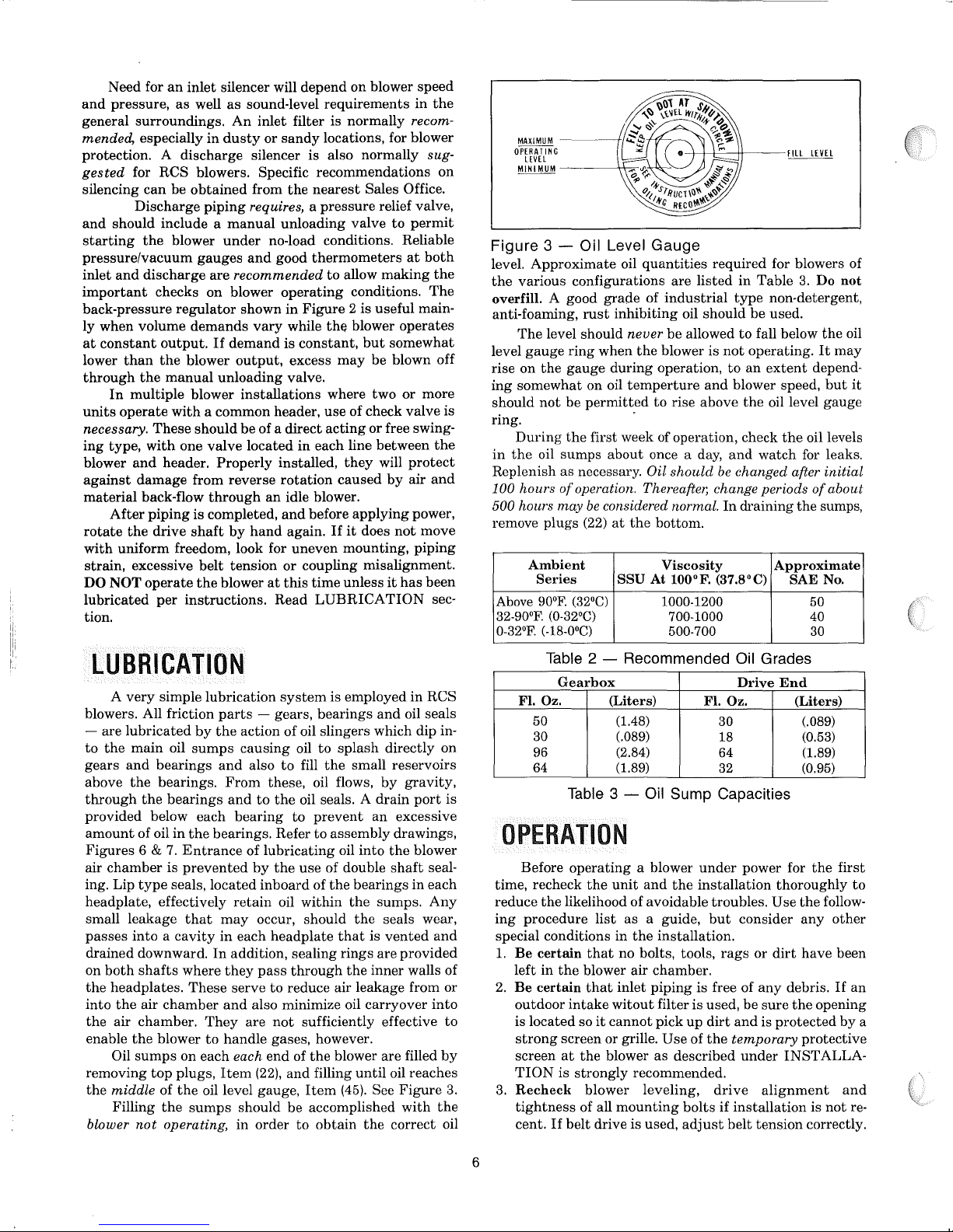
Figure 3 - Oil Level Gauge
level.
Approximate
the
various configurations are
overfill. A good
anti-foaming,
The
gauge
level
rise on
ing
somewhat
should
rust
level should
ring
when
the
gauge
on oil
not
be
permitted
ring.
in
During
the
the
first week of operation, check
oil sumps about once a day,
Replenish as necessary.
100 hours
500 hours
of
operation. Thereafter, change periods
may
be
remove plugs (22)
Ambient
Series
Above
90°F. (32°C)
32-90oF.
0-32°F. (-18-0
(0-32°C)
0
C)
Table
2 - Recommended Oil Grades
Gearbox
Fl.
Oz.
50
30
96
64
is
Table
OPERATION
to
3.
Before
time, recheck
reduce
ing
special conditions in
1.
Be
left
2.
Be
outdoor
is located so
strong
screen
TION
3.
Recheck
tightness
cent.
operating
the
the
likelihood of avoidable troubles.
procedure
certain
in
certain
list
that
the
blower air chamber.
that
intake
it
screen or grille.
at
the
is
strongly
blower leveling,
of all
If
belt drive is used,
oil
quantities
grade
of
industrial
inhibiting oil should
never
the
blower is
during
operation,
temperture
to
Oil
considered normal.
at
the
bottom.
required for blowers of
listed
in
Table
type
be
be allowed
rise above
should
to
fall below
not
operating.
to
an
and
blower speed,
the
and
watch for leaks.
be
changed after initial
In
draining
non-detergent,
extent
oil level gauge
Viscosity
SSU At tOO°F. (37.8°C)
1000-1200
700-1000
500-700
Drive
(Liters)
(1.48)
(.089)
(2.84)
(1.89)
Fl.
Oz.
30
18
64
32
3 - Oil Sump Capacities
a blower
unit
and
as
a guide,
the
no bolts, tools,
inlet
piping
witout
cannot
blower
under
the
installation
but
consider
installation.
rags
is free of
filter is used, be
pick
up
dirt
and
Use
of
the
temporary
as
described
under
power for
or
any
sure
is
recommended.
mounting
drive
bolts
adjust
alignment
if
installation
belt
tension
3.
Do
not
used.
the
It
may
depend-
but
the
oil levels
of
about
the
sumps,
Approximate
SAE
No.
50
40
30
End
(Liters)
(.089)
(0.53)
(1.89)
(0.95)
the
first
thoroughly
Use
the
follow-
any
other
dirt
have
been
debris.
protected
the
If
opening
by
protective
INST
ALLA-
and
is
not
correctly.
oil
it
to
an
a
re-
6
 Loading...