

Dresser Pacific Pumps DS Operating And Maintenance Instructions Manual
L.
DS
OPERATING AND MAINTENANCE INSTRUCTIONS
Manual No. 1100.5
PACIFIC PUMPS DIVISION 0 DRESSER INDUSTRIES INC 0 HUNTINGTON PARK, CALIF
CONTENTS
(100-D49896)
Operating and Maintenance Instructions
Type "DS"
Section 1- Installation
Section 2 - Operation
Section 3 - Troubleshooting Information
Section 4 - Maintenance
PARTS ORDERING AND SERVICING INFORMATION
Parts List
PRODUCT ENGINEERING DRAWINGS
Outline 300-D49896
Seal Flush Piping - Series 2 400-D49896
Assembly 500-D49896
Seal Assembly 515-D49896
TABLE OF CONTENTS
SECTION I — INSTALLATION
Location of Pump
A.
B.
Foundation
Leveling Baseplate
C.
D.
Grouting
E.
Installing Driver on Baseplate
F.
Alignment of Pump and Driver at the Factory
G.
Aligning Pump and Driver by User
H.
Piping
I.
Suction Piping
J.
Discharge Piping
Piping for Spare Pumps
K.
L Auxiliary Piping
M.
Stuffing Boxes
Connecting Pump and Driver
N.
SECTION II — OPERATION
Page
1
1
1
2
2
2
2
3
3
5
5
5
6
6
Preparation for Operation
A.
B.
Starting
Operating at Reduced Capacity
C.
D.
Operating Routine
E.
Stopping
SECTION III — TROUBLE SHOOTING INFORMATION
A.
No Discharge
B.
Insufficient Discharge
C.
Insufficient Pressure
D.
Cavitation and Noise
E.
Pump Loses Suction After Starting
Excessive Power Consumption
F.
Bearings Overheat
G.
H.
Vibration
SECTION IV — MAINTENANCE
A.
Disassembly
B.
Inspection and Repair
C.
Reassembly
D.
Parts Ordering
7
7
.
7
7
7
8
8
8
8
8
8
8
8
9
10
10
12
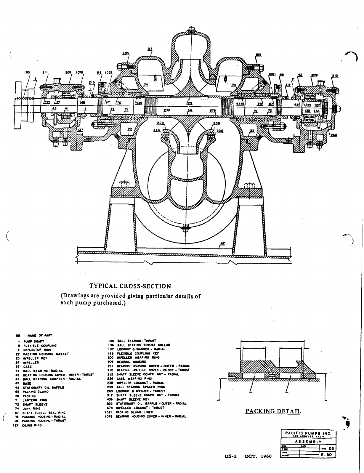
TYPICAL CROSS-SECTION
(Drawings are provided giving particular details of
each pump purchased.)
.0.
,
Areetracanmaketmorle
ketVW.S.C.CICRA
_ _VOW
Neo.
• .
BAK Of PART
03
1
Pul. SHAFT
COUPLING
FLEXISLE
7
DEFLECTOR RING
PACKING HOUSING BASKET
22
25
WELLER KEY
34
MOELLER
37
CASE
SALL BEARING-RADIAL
II
SEARING HOUSING COVER - INNER - THRUST
42
43
BALL BEARING ADAPTER - RADIAL
SAGE
47
48
STATIONARY OIL BAFFLE
AS PACKING GLAND
TO
PACKING
T I
LANTERN RING
SHAFT SLEEVE
72
74
JuNK RING
SHAFT SLEEVE SEAL RING
117
PACKING
15
PACKING HOUSING - THRuST
06
7
OILING RING
1
3
HOUSING
-
RADIAL
SALL BEARING - THRuST
135
!SA
111ALL BEARING THRUST COLLAR
13?
LOCKNUT II WASHER - RADIAL
165
FLEXIBLE COUPLING KEY
200
IMPELLER WEARING RING
BEARING HOUSING
209
BEARING HOUSING COVER - OUTER - RADIAL
211
BEARING MUSING COVER - OUTER - THRUST
212
SHAFT SLEEVE COMPR NUT - RADIAL
215
CASE WEARING RING
224
IMPELLER LOCKNUT - RADIAL
238
259
SALL BEARING SPACER RING
LOCKNUT 11 WASHER - THRUST
2110
SI?
SHAFT SLEEVE COMP*
439
SHAFT SLEEVE KEY
STATIONARY OIL BAFFLE - OUTER - RADIAL
552
IMPELLER LOCKNUT - THRUST
678
PACKING GLAND UNER
1021
BEARING HOUSING COVER - INNER - RADIAL
I 0711
Nur -
THRUST
DS-2
PACKING DETAIL
PAC
LI.F$
Ir.
1960
CICT.
IC
PUMPS
ASSEMBLY
.rg
INC
--
"
nog
Ds
1- SO
SECTION I
INSTALLATION
A. LOCATION OF PUMP
The pump should be located as near to the liquid source
1.
as possible.
Head room should be provided for the use of hoisting
2.
equipment.
The unit should be accessible for inspection during
3.
operation.
It is necessary for satisfactory operation that sufficient
4.
net positive suction head (NPSH) be available at the pump
suction flange. (Net positive suction head is the total head
in feet absolute, determined at the suction nozzle and referred to datum, less the vapor pressure of the liquid in
feet absolute.)
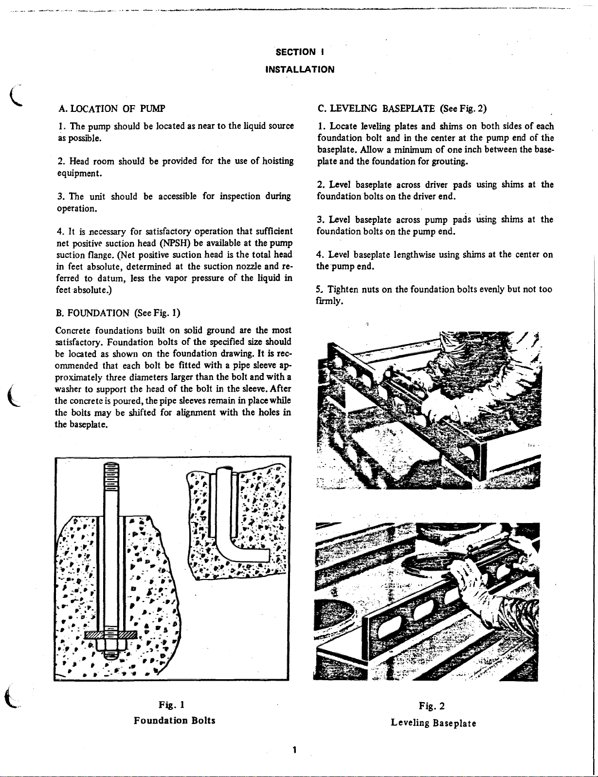
B. FOUNDATION (See Fig. 1)
Concrete foundations built on solid ground are the most
satisfactory. Foundation bolts of the specified size should
be located as shown on the foundation drawing. It is recommended that each bolt be fitted with a pipe sleeve ap-
proximately three diameters larger than the bolt and with a
washer to support the head of the bolt in the sleeve. After
the concrete is poured, the pipe sleeves remain in place while
the bolts may be shifted for alignment with the holes in
the baseplate.
C. LEVELING BASEPLATE (See Fig. 2)
I. Locate leveling plates and shims on both sides of each
foundation bolt and in the center at the pump end of the
baseplate. Allow a minimum of one inch between the baseplate and the foundation for grouting.
2.
Level baseplate across driver pads using shims at the
foundation bolts on the driver end.
3.
Level baseplate across pump pads using shims at the
foundation bolts on the pump end.
4.
Level baseplate lengthwise using shims at the center on
the pump end.
Tighten nuts on the foundation bolts evenly but not too
5.
firmly.
Fig. 1
Foundation Bolts
Fig.
2
Leveling Baseplate
1

GROUTING
D.
• Build forms to confine the grout. The forms must be
securely anchored and shored.
Remove water and waste material from foundation bolt
2.
holes and clean off and dampen the foundation slab.
the motor shaft from touching
This will prevent overheating or damage to the motor
heari ngs.
Check alignment with a straight edge across the coup-
5.
lings. The driver will be 3116 inch low before shimming.
the motor bearing faces.
3.
Pour grout through holes provided in the baseplate.
A recommended grout mixture in one part iron base aggregate. one part Portland cement and one part coarse, clean
sand by weight. Approximately 13/4 to 2 gallons of clean
water is required for each 100 pounds of mix. Use sufficient
water to make the mix placeable.
4.
Remove air pockets by working and rodding the grout
through holes in the baseplate.
After grout is set, tighten nuts on the foundation bolts.
5.
Do not remove leveling plates and shims.
E. INSTALLING DRIVER ON BASEPLATE
I. If a motor with sleeve bearings is to be used, it must be
mounted so that there is at least 1/8 inch clearance between
the thrust collars on the motor shaft and the face of the
bearings. The following procedure is usually recommended
when the pump is connected directly to the motor:
Measure the total lateral movement of the motor
a.
rotor.
It
should be approximately 1/2 inch.
Pull the rotor all the way forward toward the pump.
b.
Move the rotor 1/8 inch back from the full forward
c.
position.
2. Adjust the position of the driver so that the distance between the pump and driver shaft agrees with the callout on
the foundation drawing.
3. The various coupling types and their uses are as follows:
Limited axial end float spacer type coupling, between
a.
pump and electric motor with sleeve bearings.
b.
Standard spacer type coupling between pump and
steam turbine, between pump and fluid drive, or between
pump and electric motor with ball bearings.
F. ALIGNMENT OF DRIVERS MOUNTED AT FACTORY
It is always necessary to check, and correct if necessary, the
alignment of the pump and driver shafts after the base has
been grouted in at its permanent installation.This alignment
check must .be performed even though the pump and driver
may have been mounted and aligned at the factory prior to
shipment. The principal reasons for checking alignment
after installation are as follows:
a.
Distortion of the base may have occurred as a result
of handling during shipment or unloading.
b.
It is impractical to level base plates at the installation
site as precisely as they are leveled at the factory when the
drivers are mounted and aligned. Thus, minor distortion of
the baseplate will occur when it is bolted to the foundation,
which in turn will produce some misalignment.
The factory alignment of pumps is made without
c.
piping loads imposed upon the inlet and discharge connections. When installation is complete an alignment adjustment
is required to compensate for strain in the pump and bed
plate caused by loads transnitted from the user's piping
system.
Factory alignment of pumps is performed at an aver-
d.
age temperature of 75°F (24°C). Operation of pumps at less
than or greater than this temperature causes alignment
change due to thermal affects on pump pedestal position.
Final alignment should be made with pumps
operating temperature.
G. ALIGNING PUMP AND DRIVER BY USER (See Fig. 3)
I. Clamp a dial indicator on the driver half coupling. The
indicator bracket must be rigid to insure accuracy of the
dial indicator readings.
Set the indicator button on the outside diameter of the
2.
pump coupling hub and align the hubs to within .002 inch
total indicating reading.
at
the actual
Limited axial end float standard type coupling, be-
c.
tween fluid drive and electric motor.
4. A spacer type coupling next
pump half coupling to be removed or installed without disturbing the position of the pump or driver. The thrust bearing on the pump or fluid drive will prevent thrust collars on
to the pump
permits the
Set the indicator button on the face of the hub and
3.
align the faces parallel at all points.
To check alignment, clamp the dial indicator to the
4.
pump half coupling and take readings on the outside diameter and the face of the driver coupling hub.
2
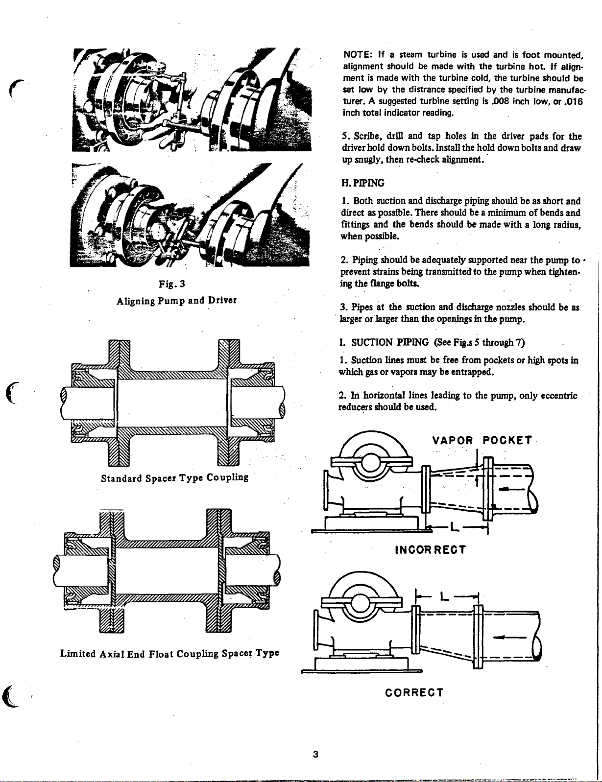
NOTE: If a
alignment should be made with the turbine hot. If alignment is made with the turbine cold, the turbine should be
set low by the distrance specified by the turbine manufacturer. A suggested turbine setting is .008 inch low, or .016
inch total indicator reading.
steam turbine is used and is foot mounted,
Fig. 3
Aligning Pump and Driver
5. Scribe, drill and tap holes in
driver hold down bolts. Install the hold down bolts and draw
up snugly, then re-check alignment.
H.
PIPING
I.
Both suction and discharge piping should be as short and
direct as possible. There should be a minimum of bends and
fittings and the bends should be made with a long radius,
when possthle.
2.
Piping should be adequately supported near the pump to •
prevent strains being transmitted to the pump when tightening the flange bolts.
3.
Pipes at the suction and discharge nozzles should
larger or larger than the openings in the pump.
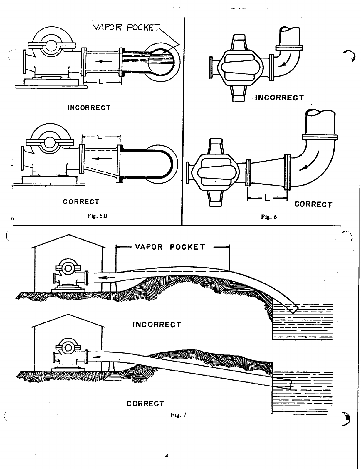
I. SUCTION PIPING (See Fig.s 5 through 7)
1.
Suction lines must be free from pockets or high spots in
which gas or vapors may be entrapped.
2.
In horizontal lines leading to the pump, only eccentric
reducers should be used.
the driver pads for the
be
as
Standard Spacer Type Coupling
Ar"
,
Limited Axial End Float Coupling Spacer Type
VAPOR POCKET
L --1
INCOR RECT
CORRECT
3
VA PO R POC KET
VAPOR POCKE T
 Loading...