

Dresser Masoneilan SVI II AP-2, Masoneilan SVI II AP-3 Quick Start Manual

Warranty
Items sold by Dresser® are warranted to be free from defects in materials and workmanship
for a period of one year from the date of shipment provided said items are used according
to Dresser recommended usages. Dresser, Inc. reserves the right to discontinue manufac
ture of any product or change product materials, design or specifications without notice. This
instruction manual applies to the following instruments and approved software: SVI ® II AP
Positioner and ValVue® software.
The SVI II AP series positioners are warranted for use only with interface software approved
by Dresser Inc. Consult Masoneilan Dresser factory locations for approved software listing.
About this Guide
This Quick Start Guide applies to the following instruments and approved software:
SVI II AP -2 through SVI II AP-3
- with Firmware version 3.1.1
- with ValVue® version 2.4 or greater
- with AMS® ValVue® SNAP-ON® version 2.4 or greater
- with Model HH375 HART® Communicator with DD published for SVI II AP
- (Masoneilan Device type 202, 0, 00CA)
The information in this manual is subject to change without prior notice.
The information contained in this manual, in whole or part, shall not be transcribed or copied
without Masoneilan’s written permission.
In no case does this manual guarantee the merchantability of the positioner or the software
or its adaptability to a specific client needs.
Please report any errors or questions about the information in this manual to your local
supplier or visit www.masoneilan.com.
Copyright
All software is the intellectual property of Dresser, Inc.
The complete design and manufacture is the intellectual property of Dresser, Inc.
Masoneilan®, FVP®, SVI®, and ValVue
®
are registered trademarks of Dresser, Inc.
All information contained herein is believed to be accurate at the time of publication
and is subject to change without notice.
Copyright 2006 by Dresser, Inc. All rights reserved.
PN 055201-167 REV C
i
This section provides safety information including safety symbols that
are used on the SVI II AP and the safety symbol definition.
Important - Please Read Before Installation!
Safety
Symbols
SVI II AP instructions contain DANGER, WARNING, and CAUTION
labels and Notes, where necessary, to alert you to safety related or
other important information. Read the instructions carefully before
installing and maintaining your instrument. DANGER and WARNING
hazards are related to personal injury. CAUTION hazards involve
equipment or property damage. Operation of damaged equipment can,
under certain operational conditions, result in degraded process
system performance that can lead to injury or death. Total compliance
with all DANGER, WARNING, and CAUTION notices is required for
safe operation.
This is the safety alert symbol. It alerts you to potential personal injury
hazards. Obey all safety messages that follow this symbol to avoid
possible injury or death.
Indicates a potentially hazardous situation, which if not avoided could
result in death or serious injury.
Indicates a potentially hazardous situation, which if not avoided could
result in serious injury.
Indicates a potentially hazardous situation, which if not avoided could
result in minor or moderate injury.
Safety Information

Masoneilan Dresser SVI II AP Quick Start Guide
ii
When used without the safety alert symbol indicates a potentially
hazardous situation, which if not avoided could result in property
damage.
Note:
Indicates important facts and conditions.
SVI II AP
Product
Safety
The SVI II AP positioner is intended for use with industrial compressed
air or, natural gas systems only. Ensure that an adequate pressure
relief provision is installed when the application of system supply
pressure could cause peripheral equipment to malfunction. Installation
must be in accordance with local and national compressed air and
instrumentation codes.
Products certified as explosion proof or flame proof equipment or for
use in intrinsically safe installations MUST BE:
Installed, put into service, used and maintained in
compliance with national and local regulations and
in accordance with the recommendations contained
in the relevant standards concerning potentially
explosive atmospheres.
Used only in situations that comply with the certifi-
cation conditions shown in this document and after
verification of their compatibility with the zone of
intended use and the permitted maximum ambient
temperature
Installed, put into service and maintained by quali-
fied and competent professionals who have undergone suitable training for instrumentation used in
areas with potentially explosive atmospheres.
Before using these products with fluids other than air or for nonindustrial applications, consult Dresser, Inc. This product is not
intended for use in life support systems.
Under certain operating conditions, the use of damaged instruments
could cause a degradation of the performance of the system which may
lead to personal injury or death.
Use only genuine replacement parts which are provided by the
manufacturer, to guarantee that the products comply with the essential
safety requirements of the European Directives mentioned on the front
cover.
Changes to specifications, structure, and compo-
nents used may not lead to the revision of this manual unless such changes affect the function and
performance of the product.

iii
Contents
Safety Symbols . . . . . . . . . . . . . . . . . . . . . . . . . . . . . . . . . . . . . . . . . . . . i
Safety Information . . . . . . . . . . . . . . . . . . . . . . . . . . . . . . . . . . . . . i
SVI II AP Product Safety . . . . . . . . . . . . . . . . . . . . . . . . . . . . . . . . . . . . ii
Section 1 Installation and Set Up . . . . . . . . . . . . . . . . . . . . . . . 1
Introduction . . . . . . . . . . . . . . . . . . . . . . . . . . . . . . . . . . . . . . . . . . . . . . 1
Using the Quick Start Guide. . . . . . . . . . . . . . . . . . . . . . . . . . . . . . . . . 2
Mounting the SVI II AP . . . . . . . . . . . . . . . . . . . . . . . . . . . . . . . . . . . . . 3
Necessary Precautions . . . . . . . . . . . . . . . . . . . . . . . . . . . . . . . . . . . . 4
Installing the SVI II AP Remote Position Sensor . . . . . . . . . . . . . . . . 4
Installation Procedure . . . . . . . . . . . . . . . . . . . . . . . . . . . . . . . . . . . . . . 5
Connecting the Tubing and Air Supply . . . . . . . . . . . . . . . . . . . . . . . . 7
Single Acting Positioner . . . . . . . . . . . . . . . . . . . . . . . . . . . . . . . . . . . . . 8
Double Acting Positioner . . . . . . . . . . . . . . . . . . . . . . . . . . . . . . . . . . . . 9
Connecting the Air Supply . . . . . . . . . . . . . . . . . . . . . . . . . . . . . . . . . . . 9
Wiring the SVI II AP . . . . . . . . . . . . . . . . . . . . . . . . . . . . . . . . . . . . . . . 10
Connecting to the Control Loop . . . . . . . . . . . . . . . . . . . . . . . . . . . . . . 10
Wiring Guidelines . . . . . . . . . . . . . . . . . . . . . . . . . . . . . . . . . . . . . . . . 10
SVI II AP Setups . . . . . . . . . . . . . . . . . . . . . . . . . . . . . . . . . . . . . . . . . 11
Grounding Practices . . . . . . . . . . . . . . . . . . . . . . . . . . . . . . . . . . . . . . 12
Compliance Voltage in Single Drop Current Mode . . . . . . . . . . . . . . . 12
Verify Wiring and Connections . . . . . . . . . . . . . . . . . . . . . . . . . . . . . . 12

Masoneilan Dresser SVI II AP Quick Start Guide
iv
SVI II AP Maintenance . . . . . . . . . . . . . . . . . . . . . . . . . . . . . . . . . . . . . 14
Repair . . . . . . . . . . . . . . . . . . . . . . . . . . . . . . . . . . . . . . . . . . . . . . . . . 14
Tools Needed for Cover Replacement . . . . . . . . . . . . . . . . . . . . . . . . . 14
Display Cover Removal and Installation . . . . . . . . . . . . . . . . . . . . . . . 15
Removing the SVI II AP Display Cover . . . . . . . . . . . . . . . . . . . . . . . 15
Installing the SVI II AP Display Cover . . . . . . . . . . . . . . . . . . . . . . . . 15
Section 2 Check Out, Configuration and Calibration . . . . . . 17
Overview. . . . . . . . . . . . . . . . . . . . . . . . . . . . . . . . . . . . . . . . . . . . . . . . 17
Check Out Procedures . . . . . . . . . . . . . . . . . . . . . . . . . . . . . . . . . . . . 17
Physical Inspection . . . . . . . . . . . . . . . . . . . . . . . . . . . . . . . . . . . . . . . 17
Actuator, Linkages, or Rotary Adapter . . . . . . . . . . . . . . . . . . . . . . . 17
Verify Mounting and Linkage Adjustment . . . . . . . . . . . . . . . . . . . . . 18
Checking the Magnet . . . . . . . . . . . . . . . . . . . . . . . . . . . . . . . . . . . . 18
Performing a Visual Inspection . . . . . . . . . . . . . . . . . . . . . . . . . . 18
Using ValVue 2.4 to Check Magnet Position . . . . . . . . . . . . . . . . . . . . 19
Checking the Air Supply . . . . . . . . . . . . . . . . . . . . . . . . . . . . . . . . . . . 20
Checking the Electronic Module Connections . . . . . . . . . . . . . . . . . . . 20
Making Connections to the Terminal Board . . . . . . . . . . . . . . . . . . . . . 22
Operational Checkout . . . . . . . . . . . . . . . . . . . . . . . . . . . . . . . . . . . . . 22
Connecting to the Current Source . . . . . . . . . . . . . . . . . . . . . . . . . . . . 22
Pushbutton Locks and Configuration-Lock Jumper . . . . . . . . . . . . . . . 23
Hardware Configuration Lock . . . . . . . . . . . . . . . . . . . . . . . . . . . . . . 23
Powering Up the SVI II AP . . . . . . . . . . . . . . . . . . . . . . . . . . . . . . . . . 23
Configuration . . . . . . . . . . . . . . . . . . . . . . . . . . . . . . . . . . . . . . . . . . . . 24
ValVue 2.4 Software . . . . . . . . . . . . . . . . . . . . . . . . . . . . . . . . . . . . . . 24
ValVue 2.4 Lite . . . . . . . . . . . . . . . . . . . . . . . . . . . . . . . . . . . . . . . . . 24
System Requirements . . . . . . . . . . . . . . . . . . . . . . . . . . . . . . . . . . . 25
ValVue 2.4 Full Trial Version . . . . . . . . . . . . . . . . . . . . . . . . . . . . . . . 25
Pushbuttons and Local Display . . . . . . . . . . . . . . . . . . . . . . . . . . . . . . 25
Pushbuttons . . . . . . . . . . . . . . . . . . . . . . . . . . . . . . . . . . . . . . . . . . . . . 26
Configuration with Pushbuttons . . . . . . . . . . . . . . . . . . . . . . . . . . . . . . 27
Viewing Configuration Data . . . . . . . . . . . . . . . . . . . . . . . . . . . . . . . 27
Viewing Status Messages . . . . . . . . . . . . . . . . . . . . . . . . . . . . . . . . . . 27
VIEW DATA Settings . . . . . . . . . . . . . . . . . . . . . . . . . . . . . . . . . . . . . . 28

v
Calibration . . . . . . . . . . . . . . . . . . . . . . . . . . . . . . . . . . . . . . . . . . . . . . 28
Auto Tune . . . . . . . . . . . . . . . . . . . . . . . . . . . . . . . . . . . . . . . . . . . . . 29
Check-out with a HART Handheld Communicator . . . . . . . . . . . . . . . . 31
Appendix A Specifications and References . . . . . . . . . . . . . 1
Physical and Operational Specifications . . . . . . . . . . . . . . . . . . . . . . 1
Hazardous Location Installation . . . . . . . . . . . . . . . . . . . . . . . . . . . . . 7

Masoneilan Dresser SVI II AP Quick Start Guide
vi
1
1
Installation and Set Up
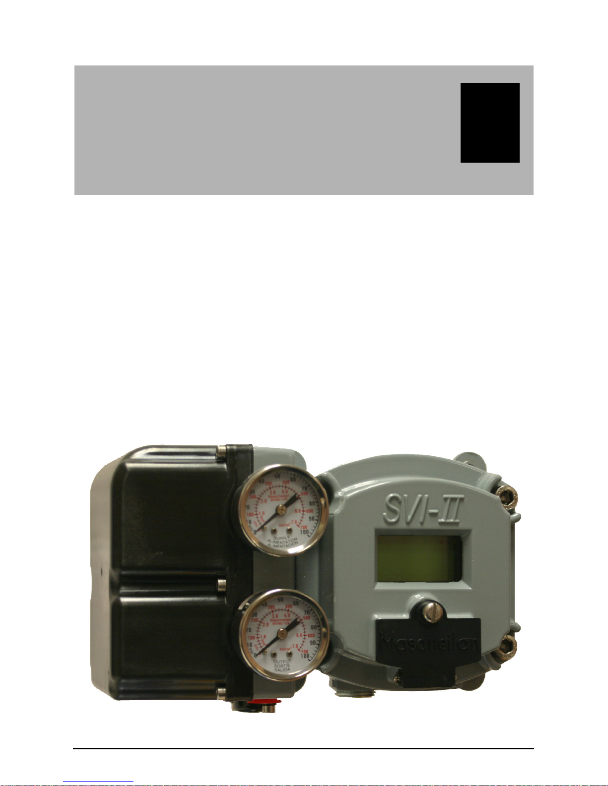
Introduction The SVI
®
II AP (Smart Valve Interface) is the next generation of
Masoneilan’s intelligent digital valve positioners. The SVI II AP is a
compact, industrial tough, high performance, digital valve positioner
that combines a local display with remote communication and
diagnostic capabilities. The SVI II AP is available with options needed
to fulfill virtually all application requirements and communicates using
the HART® protocol. The SVI II AP offers:
Extreme Accuracy
Extreme Reliability
Extreme Digital Precision
Automated Valve Commissioning
Precise, Quick, Responsive Control of Valve
Position
Sophisticated Valve Diagnostics
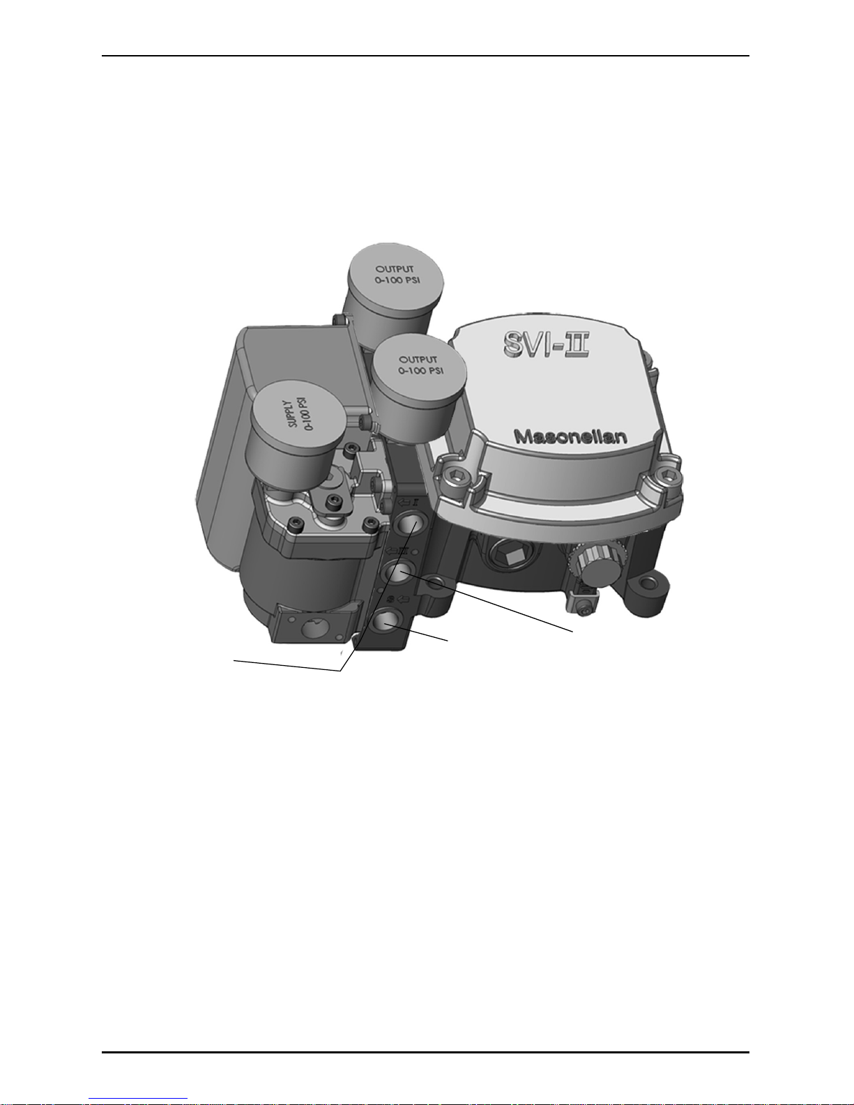
Figure 1 SVI II AP
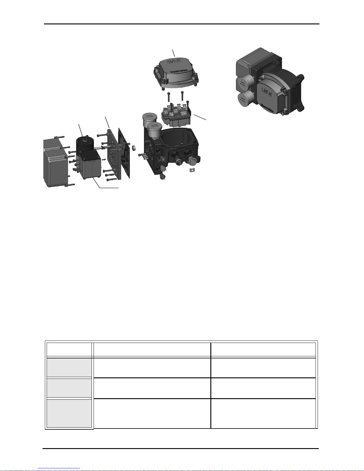
SVI II AP Cover
SVI II AP Assembled
Electronics
Module
Pneumatic Train and
Cover (I/P Module, Relay)
Manifold
Relay
I/P
Masoneilan Dresser SVI II AP Quick Start Guide
2
Figure 2 SVI II AP Components
Using the
Quick Start
Guide
The SVI II AP Quick Start Guide is intended to help an experienced
Field Engineer install, setup, and calibrate an SVI II AP in the most
efficient manner possible. This document provides basic installation
and setup instructions and is not intended to replace the in-depth
information contained in the SVI II AP Instruction Manual EW2002-AP.
If you experience problems that are not documented in this guide refer
to the Masoneilan SVI II AP Instruction Manual EW2002-AP, call your
local Masoneilan representative, or go to www.masoneilan.com. Sales
offices are listed on the last page of this document
The steps necessary to complete the SVI II AP installation and software
setup are outlined in Table 1 below.
Table 1 SVI II AP Installation Steps
Step No. Procedure Reference
1 Attach mounting bracket to the
actuator.
See page 3 for rotary valve and
reciprocating valve instructions.
2 Install the SVI II AP magnetic
assembly (rotary valves only).
See page 3 for instructions.
3 Assemble the SVI II AP on the
bracket that is mounted to the valve
actuator.
See page 3 for rotary valve and
reciprocating valve instructions.

Installation and Set Up Mounting the SVI II AP
3
Failure to adhere to the requirements listed in this manual may cause
loss of life and property.
Before installing, using, or carrying out any maintenance tasks
associated with this instrument, READ THE INSTRUCTIONS
CAREFULLY. (Refer to
“Hazardous Location Installation” on
page A-7 of this guide for detailed instructions.)
Mounting the
SVI II AP
This guide provides installation instructions for mounting an SVI II AP
on both rotary and reciprocating actuated valves. The mounting
process can be broken down into the following:
Attach the mounting bracket to the actuator.
Install the magnetic assembly.
Assemble the SVI II AP on the mounting bracket.
Note: The SVI II AP should be mounted with the conduit connections
down in order to facilitate drainage of condensate from the con
-
duit.
4 Install the Remote Position Sensor, if
necessary.
See page 4 for instructions.
5 Connect the pneumatic tubing to the
SVI II AP.
See page 7 for instructions.
6 Connect the air supply to the SVI II
AP.
See page 9 for instructions.
7 Connect the positioner to the HART
Control Loop segment by installing
the SVI II AP wiring.
See page 10 for instructions.
8 Configure/calibrate using ValVue.2.4 See page 24 and page 28 for
instructions
Configure/calibrate using a HART
Hand Held Communicator
See page 31 for instructions.
Table 1 SVI II AP Installation Steps
Step No. Procedure Reference

Masoneilan Dresser SVI II AP Quick Start Guide
4
Necessary Precautions
To avoid injury or the process being affected when installing or
replacing a positioner on a control valve, ensure that:
If the valve is located in a hazardous area make
sure the area has been certified as “safe” or that all
electrical power to the area has been disconnected
before removing any covers or disconnecting any
leads.
Shut off air supply to the actuator and to any valve
mounted equipment.
Ensure the valve is isolated from the process by
either shutting off the process or using bypass
valves for isolation. Tag shutoff or bypass valves to
guard against a “turn-on” while work is in progress.
Bleed air from actuator and check that valve is in its
unenergized position.
It is now safe to disconnect and remove any valve mounted equipment
that is being replaced.
For the procedure to mount rotary and reciprocating valves, refer to the
Mounting Instructions contained in the valve’s Mounting Box kit.
Installing the
SVI II AP
Remote
Position
Sensor
An option that is available for the SVI II AP is the Remote Position
Sensor. The Remote Position Sensor, is a remotely mounted positionsensing device, that is connected electrically to an SVI II AP valve
positioner. It is used as position feedback in applications where direct
mounting of an SVI II AP to a valve actuator is not practical due,
typically but not limited to, extreme vibration, heat or radiation.
The Remote Position Sensor is a potentiometer located in an enclosure
which can be mounted on a valve or damper to indicate stem position
when connected to a suitable receiver. There is a three wire connection
provided on a screw terminal block to interconnect to the receiving
device.
The SVI II AP Remote Position Sensor is suitable for installation
outdoors in an industrial environment. Mounting kits are provided to
permit mounting on a variety of valves.
Do not remove the instrument cover or connect to an electrical circuit in
a Hazardous Area unless the power is disconnected.
Comply with current national and local regulations
for electrical installation work.

Installation and Set Up Installing the SVI II AP Remote Position Sensor
5
Comply with national and local explosive
atmosphere regulations.
Before carrying out any work on the device, power
off the instrument or make sure that the locale
conditions for potentially explosive atmosphere
permit the safe opening of the cover.
Installation Procedure
For the Remote Position Sensor installation procedure refer to the
mounting instructions provided with the Remote Position Sensor.
1. Remove the cover from the Remote Position Sensor
assembly by turning the cover in a counter-clockwise (fac
-
ing the cover) direction.
2. Connect the Remote Position Sensor to the mounting
bracket by inserting four M6 x 20 mm Socket Head Cap
Screws through the appropriate screws holes (according
to the valve) on the Remote Position Sensor bracket and
using a 3⁄16 inch Hex Key with tee handle.
3. Route the instrument cable from the SVI II AP to the
Remote Position Sensor (see Figure 3 on page 6 for
installation instructions).
4. Thread the cable through the conduit at the bottom of the
Remote Position Sensor.
5. Using a blade screwdriver, loosen the screws on the
terminal block and connect the black, brown and red wires
to the appropriate labelled connectors.
6. Tighten the screws.
7. Attach the feedback lever to the Remote Position Sensor
shaft. From the cover side, the lever should be pointing to
the left for reciprocating valves and to the right for rotary
valves.
8. Place the Remote Position Sensor on the mounting
bracket.
9. Attach the Remote Position Sensor and secure the
turnbuckle to the lever ensuring that the shaft at the rear of
the Remote Position Sensor is inserted into the valve
actuator. (Refer to
Table 2 “Remote Position Sensor
Turnbuckle Length” below for turnbuckle length.)
10. Replace the Remote Position Sensor cover.
Table 2 Remote Position Sensor Turnbuckle Length
Actuator Size Stroke Turnbuckle Length
6 and 10 0.5 - 0.8 inch 1.25 inch
10 0.5 - 0.8 inch 1.25 inch
10 >0.8 – 1.5 inch 1.25 inch
Masoneilan Dresser SVI II AP Quick Start Guide
6
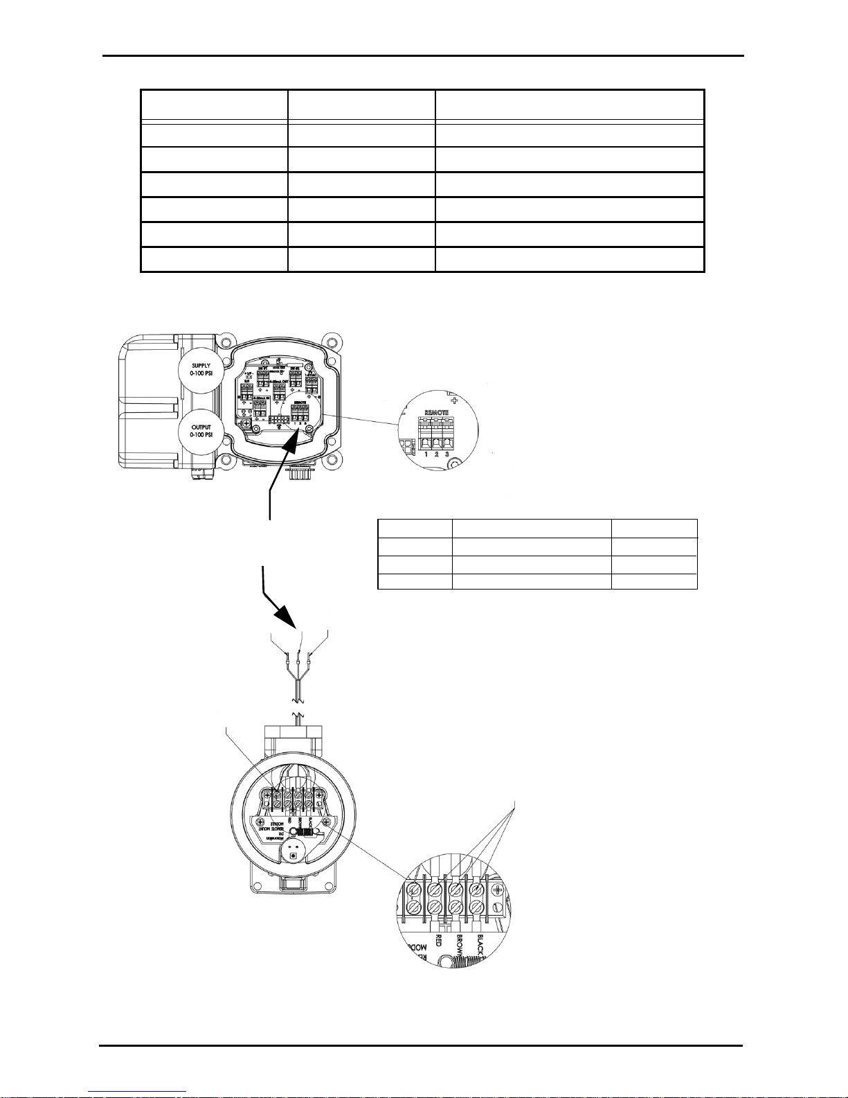
Figure 3 SVI II AP Remote Position Sensor Installation
16 0.5 - 0.8 inch 2.90 inch
16 >0.8 – 1.5 inch 2.90 inch
16 >1.5 – 2.5 inch 2.90 inch
23 0.5 - 0.8 inch 5.25 inch
23 >0.8 – 1.5 inch 5.25 inch
23 >1.5 – 2.5 inch 5.25 inch
Step 1
Connect Drain Wire
to Open Terminal
Step 2
When connecting cable to
Remote Position Sensor make sure wire
colors match:
- Red to Red
- Brown to Brown
- Black to Black
Step 3
Insert Ferrules into “Remote”
Terminal Block according to
Wire Color SVI II AP Terminal Number Function
Red
Brown
Black
1
2
3
Positive
Signal
Ground
the chart at the right:
Remote Terminal Block
123
Table 2 Remote Position Sensor Turnbuckle Length
Actuator Size Stroke Turnbuckle Length
Installation and Set Up Connecting the Tubing and Air Supply
7
Connecting
the Tubing
and Air
Supply
The last step in hardware installation for the SVI II AP is to connect the
air supply to the positioner. This section describes the process for
connecting the tubing and air supply to a single and double acting
positioner.
Isolate the valve from the process and disconnect air tubing from the
positioner. Disconnect air fully to avoid injury or process damage.
1. Install the pneumatic tubing using a regulated, clean,
instrument air supply to the air supply port (S
←)
2. For a single acting actuator - pipe the outbound air from
the output pressure port (←I) to the valve actuator.
3. For a double acting actuator - pipe the air going out of
each side of valve actuator. Use both output pressure port
one (
←I) for one side of the actuator and output pressure
port two (←II) for the other side of the actuator.
4. Connect air supply and actuator outports (1⁄4 inch NPT)
Supply pressure for single acting SVI II AP:
20 -100 psi (1.4 - 6.9 bar) (138 - 690 kPa)
Supply pressure for double acting SVI II AP:
20 - 150 psi (1.4 - 10.4 bar) (138 - 1035 kPa)
Minimum tubing diameter 1⁄4 inch (6mmx4mm)
Note: The SVI II AP Digital Positioner is designed to operate with
clean, dry, oil-free, instrument grade air to ANSI-ISA-57.3 1975
(R1981) or ISA-S7.3-1975 (R1981) or with a sweet natural gas
supply (SVI II AP models SVI II AP-2 through SVI II AP-3).
Table 3
Dew Point At least 18° F (10° C) below minimum anticipated ambient
temperature
Particulate Matter Filtered to 5 microns
Oil Content Less than 1 ppm w/w
Contaminants Free of all corrosive contaminants
Air Supply Requirements

Masoneilan Dresser SVI II AP Quick Start Guide
8
Single Acting Positioner
The supply and output connections for the SVI II AP, located on bottom
of the pneumatic block, are tapped 1⁄4 inch NPT. Output is toward the
front, supply is toward the back. Two pressure gauges, output on top,
supply on bottom, are located on the front of the pneumatic block.
Maximum allowable air supply pressure to the SVI II AP varies
according to actuator, valve size, and valve type. See Pressure Drop
tables in valve specification sheets to determine the correct positioner
supply pressure. Minimum supply pressure should be 5 to 10 psi above
maximum spring pressure but may not exceed the rated actuator
pressure.
Output
Supply
Figure 4 Air Ports on Single Acting Positioner
Installation and Set Up Connecting the Tubing and Air Supply
9
Double Acting Positioner
Connect Output 1, labeled “(←I)” to the inlet port of the actuator and
connect Output 2 labeled “(
←II)” to the opposing actuator port (see
Figure 5 below for double acting ports.
Output
I
Connector
Supply
Connector
Connector
Output
II
Figure 5 Air Ports on Double Acting Positioner
Connecting the Air Supply
After the tubing is installed, use the following procedure to connect the
air supply.
1. Connect a supply of clean, dry compressed air to the filter
regulator.
2. Turn on the air supply.
3. Adjust the filter regulator.
4. Supply pressure must be 5 - 10 psi greater than the spring
range of the actuator but may not exceed the rated
actuator pressure. Refer to the valve or actuator
instruction manual.

Masoneilan Dresser SVI II AP Quick Start Guide
10
Wiring the
SVI II AP
In order for the SVI II AP to communicate the positioner data the SVI II
AP must be physically connected to a HART communication. The
procedure below outlines wiring the SVI II AP.
Comply with current national and local regulations
for electrical installation work.
Comply with national and local explosive
atmosphere regulations.
Before carrying out any work on the device, power
off the instrument or make sure that the locale
conditions for potentially explosive atmosphere
permit the safe opening of the cover.
Connecting to the Control Loop
The SVI II APpositioner MUST BE grounded according to local
regulations. It is important to maintain correct polarity at all times,
otherwise the positioner may not operate properly. The SVI II AP
should be physically connected to the HART loop using a cable
specified by the HART Communication Foundation. A shielded cable
is recommended.
To connect the Control Loop to the SVI II AP:
1. Connect one end of the cable to the control loop's
4 - 20mA output
2. Remove the threaded wiring covers on the positioner.
3. Connect the other end of the cable to the SVI II AP. There
are two threaded openings on the positioner. Use the
opening with the red plastic insert.
4. Maintain polarity + and - respectively.
Wiring Guidelines
This list contains eight guidelines for a successful implementation of DC
current signal, DC power, and HART communication to the SVI II AP:
1. Compliance voltage at the SVI II AP must be 9 volts at the
maximum current of 20 mA.
2. Signal to the SVI II AP must be a regulated current in the
range 3.2 to 22 mA.
3. Controller output circuit must be unaffected by the HART
tones which are in the frequency range between 1200 and
2200 Hz.
4. Frequency range of the HART tones must have a circuit
impedance of more than 220 Ohms, typically 250 Ohms.
5. HART tones may be imposed by the positioner and a
communication device located anywhere on the signaling
circuit.
 Loading...