

Dresser Masoneilan SVI II AP Instruction Manual
Putting You In Control
Instruction Manual
EW2002-AP
06/10 Rev D
SVI® II AP
Digital Positioner
With Remote Position Sensor

Warranty
Items sold by Dresser ,® Inc. are warranted to be free from defects in materials and workmansh ip for a
period of one year from the date of shipment provided said items are used according to Dresser
recommended usages. Dresser, Inc. reserves the right to discontinue manufacture of any product or
change product materials, design or specifications without notice.
This instruction manual applies to the following instruments and approved software: SVI
Positioner and ValVue
The SVI II AP series positioners are warranted for use only with interface software approved by
Dresser, Inc. Consult Masoneilan Dresser factory locations for approved software listing.
About this Guide
This Instruction Manual applies to the following instruments and approved software:
q SVI II AP -2 through SVI II AP -3
q - with Firmware version 3.1.1, 3.1.2 or 3.2.1 q - with ValVue q - with AMS q with ValVue PRM Pug-in q - with Model HH375 HART
The information in this manual is subject to change without prior notice.
The information contained in this manual, in whole or part, shall not be transcribed or copied without
Masoneilan’s written permission.
®
software.
®
version 2.4 or greater
®
ValVue® SNAP-ON® version 2.4 or greater
®
Communicator with DD published for SVI II AP
®
II AP
Copyright
In no case does this manual guarantee the merchantability of the positioner or the software or its
adaptability to a specific client needs.
Please report any errors or questions about the information in this manual to your local supplier or
visit www.masoneilan.com.
All software is the intellectual property of Dresser, Inc.
The complete design and manufacture is the intellectual property of Dresser, Inc.
Masoneilan
contained herein is believed to be accurate at the time of publication an d is subject to change without
notice.
Copyright 2010 by Dresser, Inc. All rights reserved.
PN 055201-241 Rev. D
®
, FVP®, SVI®, and ValVue
®
are registered trademarks of Dresser, Inc. All information
Safety Information
Important - Please Read Before Installation!
WARNING
CAUTION
This section provides safety information including safety symbols that are used on the SVI II
AP and the safety symbol definition.
Safety Symbols
SVI II AP instructions contain WARNINGS, CAUTIONS labels and Notes, where necessary,
to alert you to safety related or other important information. Read the instructions carefully
before installing and maintaining your instrument. WARNING hazards are related to personal
injury. CAUTION hazards involve equipment, property or data damage. Operation of
damaged equipment can, under certain operational conditions, result in degraded process
system performance that can lead to injury or death. Total compliance with all WARNING, and
CAUTION notices is required for safe operation.
Indicates a potentially hazardous situation, which if not avoided cou ld result in
serious injury.
Indicates a potentially hazardous situation, which if not avoided cou ld result in
property damage.
i
Masoneilan Dresser
NOTE
Indicates important facts and conditions.
SVI II AP Product Safety
The SVI II AP positioner is intended for use with industrial compressed air or , natural gas
systems only.
NOTE Installations using natural gas are Zone 0 or Div 1
Ensure that an adequate pressure relief provision is installed when the application of
system supply pressure could cause peripheral equipment to malfunction. Installation
must be in accordance with local and national compressed air and instrumentation codes.
SVI II AP Instruction Manual
installations.
Products certified as explosion proof or flame proof equipment or for use in intrinsically
safe installations MUST BE:
/8/10
q Installed, put into service, used and maintained in compliance with national and
local regulations and in accordance with the recommendations contained in the
relevant standards concerning potentially explosive atmospheres.
q Used only in situations that comply with the certification conditions shown in this
document and after verification of their compatibility with the zone of intended use
and the permitted maximum ambient temperature.
DRAFT 6
q Installed, put into service and maintained by qualified and competent professionals
who have undergone suitable training for instrumentation used in areas with
potentially explosive atmospheres.
Before using these products with fluids other than air or for non-industrial applications,
consult Dresser, Inc. This product is not intended for use in life support systems.
Use only genuine replacement parts which are provided by the manufacturer, to
guarantee that the products comply with the essential safety requirements of the
European Directives.
WARNING Under certain operating conditions, the use of damaged
instruments could cause a degradation of the performance of
the system, which can lead to personal injury or death.
Changes to specifications, structure, and components used may not lead to the revision
of this manual unless such changes affect the function and performance of the product.
ii

SVI II AP Instruction Manual
Contents
Safety Information ...............................................................................................................................i
Safety Symbols.............................................................................................................................. i
SVI II AP Product Safety................................................................................................................ii
1: Introduction ....................................................................................................................................1
ValVue Software...........................................................................................................................2
ValVue Lite..............................................................................................................................2
System Requirements.............................................................................................................2
ValVue Trial Version ...............................................................................................................2
Operational Overview ...................................................................................................................3
SVI II AP Features........................................................................................................................3
Available Options....................................................................................................................5
About This Manual........................................................................................................................5
Conventions Used in This Manual ..........................................................................................5
2: Installation and Set Up ...................................................................................................................7
Overview.......................................................................................................................................7
SVI II AP Dimensions and Weights.........................................................................................9
Pre-Installation Issues.................................................................................................................10
Storage.................................................................................................................................. 10
Unpacking.............................................................................................................................10
Installation Steps.........................................................................................................................10
Installation Notes ........................................................................................................................11
Before Powering Up..............................................................................................................12
Mounting the Positioner ........................................................................................................12
Filter Regulator and Tubing...................................................................................................13
Mounting the SVI II AP on Rotary Valves...................................................................................13
Required Tools......................................................................................................................13
Rotary - 90°...........................................................................................................................16
Magnet Orientation on Rotary Valve Shafts..........................................................................17
Dismantling the SVI II AP from Rotary Valves......................................................................17
Mounting the SVI II AP on Reciprocating Valves........................................................................17
Mounting the SVI II AP on a Reciprocating Actuator ............................................................17
Dismantling the SVI II AP from Reciprocating Valves........................................................... 20
Installing the SVI II AP for Double- Acting Operation..................................................................21
Installing the SVI II AP Remote Position Sensor ........................................................................ 23
Remote Position Sensor Mounting Instructions....................................................................24
Configuring the SVI II AP for Remote Position Sensing........................................................27
Connecting the Tubing and Air Supply .......................................................................................29
Single Acting Positioner........................................................................................................30
Double Acting Positioner.......................................................................................................31
Connecting the Air Supply.....................................................................................................32
DRAFT 6/8/10
iii

Dresser Masoneilan
Wiring the SVI II AP....................................................................................................................33
Connecting to the Control Loop............................................................................................ 33
Verify Wiring and Connections.............................................................................................. 33
3: Check Out and Power Up ............................................................................................................ 35
Overview.....................................................................................................................................35
Position Sensor Principles..........................................................................................................35
Check Out Procedures................................................................................................................ 36
Physical Inspection.....................................................................................................................36
Actuator, Linkages, or Rotary Adapter..................................................................................36
Verify Mounting and Linkage Adjustment ............................................................................. 37
Checking the Magnet............................................................................................................37
Checking the Air Supply........................................................................................................39
Checking the Electronic Module Connections ...................................................................... 40
Operational Checkout.................................................................................................................42
Connecting to the Current Source ........................................................................................ 42
Powering Up the SVI II AP....................................................................................................42
Pushbutton Locks and Configuration-Lock Jumper.............................................................. 43
4: Using the Digital Interfaces ..........................................................................................................45
Overview.....................................................................................................................................45
8/10
DRAFT 6/
Local Display and Pushbuttons.............................................................................................45
HART Handheld Communicator ........................................................................................... 45
ValVue ..................................................................................................................................46
Pushbuttons and Local Display...................................................................................................46
Pushbuttons.......................................................................................................................... 47
Display Menus ............................................................................................................................ 49
NORMAL Operating Mode and MANUAL Mode Menus.......................................................49
Configure Menu ....................................................................................................................50
Calibration Menu...................................................................................................................54
VIEW DATA Menu................................................................................................................ 55
FAILSAFE Mode...................................................................................................................57
VIEW ERR Diagnostics Messages.......................................................................................58
Display and Clear Error Messages.............................................................................................61
Positioner Fault Messages....................................................................................................61
Return to Normal Operation..................................................................................................62
Hand Held Communicator...........................................................................................................62
ValVue ........................................................................................................................................63
Installation of ValVue Software, and Registration................................................................. 63
System Requirements...........................................................................................................64
SVI II AP Instruction Manual
5: Configuration and Calibration ......................................................................................................65
Configuration and Calibration .....................................................................................................65
ValVue Software...................................................................................................................65
Pushbuttons and Local Display for Configuration and Calibration........................................66
Pushbuttons Summary..........................................................................................................66
Pushbutton Locks and Configuration-Lock Jumper.............................................................. 67
Hardware Configuration Lock ...............................................................................................67
iv

Configuration with Pushbutton Display.......................................................................................67
Viewing Configuration Data...................................................................................................68
VIEW DATA Settings ............................................................................................................69
Calibration...................................................................................................................................71
Calibrating the SVI II AP Unit Using Pushbuttons................................................................. 71
Correct for Over Travel .........................................................................................................72
Adjust Input Signal Range.....................................................................................................73
Check-out with a HART Handheld Communicator......................................................................75
Configuring and Calibrating with ValVue ....................................................................................77
Installation of Cover....................................................................................................................77
6: Wiring an SVI II AP ......................................................................................................................79
Overview.....................................................................................................................................79
System Connections...................................................................................................................79
Wiring Guidelines........................................................................................................................80
SVI II AP Setups ...................................................................................................................81
Grounding Practices..............................................................................................................84
Compliance Voltage in Single Drop Current Mode...............................................................84
Wire Size and Conduit ..........................................................................................................85
HART Physical Layer Compliance of the Control System..........................................................86
Impedance Constraints.........................................................................................................86
Noise Constraints..................................................................................................................86
Cabling and Interconnection Requirements..........................................................................87
Capacitance vs. Length of Cable for HART..........................................................................87
HART Filter Required for Certain Control System Output Circuits........................................87
Split Range Applications.............................................................................................................88
Setting Loop Addresses for Split Range Systems................................................................89
Multiple Output Circuit Control System.................................................................................90
Isolators................................................................................................................................. 91
Supplemental Power Supply................................................................................................. 93
Verify Wiring and Connections..............................................................................................93
Required Practices for Explosion Proof Installations.................................................................. 94
Clarification of Terminology...................................................................................................95
Recommended Practice for Severe or Humid Environments................................................95
DRAFT 6/8/10
7: HART Communications with Intrinsic Safety ...............................................................................97
Overview.....................................................................................................................................97
HART Barrier Compliance ..........................................................................................................98
Output Channel Isolation ............................................................................................................99
HART Filter Requirements..........................................................................................................99
Modem and Computer Use in Intrinsically Safe Circuits...........................................................101
MACTek Intrinsically Safe modem, Model 010005 ............................................................101
MACTek Warning ...............................................................................................................101
Use of Handheld Communicators In Intrinsically Safe Circuits...........................................101
8: Operation and Maintenance .......................................................................................................103
Principle of Operation ...............................................................................................................103
v

Dresser Masoneilan
Physical and Operational Description....................................................................................... 104
Electronics Module..............................................................................................................104
Output Switches..................................................................................................................105
Pneumatic Module.............................................................................................................. 106
Optional Display and Pushbuttons......................................................................................109
SVI II AP Maintenance and Repair...........................................................................................109
Repair .................................................................................................................................109
Tools Needed......................................................................................................................110
Display Cover Removal and Installation.............................................................................110
I⁄P Module Removal and Installation...................................................................................112
Relay Removal and Installation ..........................................................................................113
Adjusting I/P Zero ...............................................................................................................113
Connecting Components to the Electronics Module...........................................................113
Repair by Replacement ............................................................................................................114
Internal Diagnostics ..................................................................................................................114
FAILSAFE Mode ................................................................................................................114
Upgrading Firmware ................................................................................................................. 114
Tools Required....................................................................................................................115
Installing Firmware Upgrade...............................................................................................115
SVI II AP Instruction Manual
A: Specifications and References ..................................................................................................117
8/10
Physical and Operational Specifications...................................................................................117
Spare Parts...............................................................................................................................123
B: Air to Open and Air to Close Actuators .....................................................................................127
Actuator Action.......................................................................................................................... 127
C: Air Supply Requirements ..........................................................................................................131
Air Supply Requirements..........................................................................................................131
D: Adjusting Speed of Response ...................................................................................................133
DRAFT 6/
Adjusting Speed of Response...................................................................................................133
E: Advanced Usage ....................................................................................................................... 135
Technology to Maximize Savings and Process Performance................................................... 135
Tight Shutoff Application to Protect from Seat Erosion....................................................... 135
Tight Shutoff Application to High Pressure Liquid Letdown Valve Trim.............................. 135
Using ValVue Diagnostics......................................................................................................... 136
Continuous Diagnostics...................................................................................................... 136
Monitoring a Valve Bellows Seal.........................................................................................136
Critical Service, Cavitation Control Trim.............................................................................136
Diagnostic Valve Tests .......................................................................................................137
F: Glossary .................................................................................................................................... 139
vi

SVI II AP Instruction Manual
Figures
1 SVI II AP ................................................................................................................................1
2 SVI II AP Components...........................................................................................................8
3 SVI II AP Dimensions.............................................................................................................9
4 Camflex with Mounting Bracket (Side View)........................................................................14
5 Camflex ATO Mounting (Front View)...................................................................................15
6 Mounting Bracket on Air-to-Close Actuator..........................................................................15
7 Model 33 Actuator................................................................................................................16
8 Magnet Holder for Reciprocating Valves.............................................................................18
9 Reciprocating Valve Mounting Bracket................................................................................19
10 Lever for Model 87/88 Multispring Actuator.........................................................................19
11 Reciprocating Linkage .........................................................................................................20
12 84/85/86 Valve.....................................................................................................................21
13 Stroke Settings.....................................................................................................................21
14 Bracket Configuration Strokes .5 - 2.50” and 3-6” ...............................................................22
15 Magnet Position with Valve Closed......................................................................................22
16 Lever Alignment...................................................................................................................22
17 Remote Position Sensor Mounting ......................................................................................25
18 Remote Position Sensor (Cover Removed) and Wiring.......................................................26
19 Installing SMARTS Assistant from CD.................................................................................27
20 SMARTS Assistant - Commissioning the Remote Position Sensor..................................... 28
21 Air Ports on Single Acting Positioner...................................................................................30
22 Air Ports on Double Acting Positioner..................................................................................31
23 Magnet Orientation for Rotary Valves with Valve Closed.................................................... 37
24 Magnet Orientation for 90° Valve Rotation with De-energized Actuator.............................. 38
25 Magnet Holder for Reciprocating Valves.............................................................................38
26 Reciprocating Valve Mounting Bracket................................................................................39
27 Connections to Electronics Module (via Terminal Board)....................................................41
28 SVI II AP Display..................................................................................................................47
29 NORMAL Operation and MANUAL Menu Structures ..........................................................49
30 CONFIGure Menu................................................................................................................50
31 CALIBration Menu................................................................................................................54
32 VIEW DATA Menu...............................................................................................................56
33 FAILSAFE Menu..................................................................................................................58
34 ValVue Options....................................................................................................................64
35 Configuration Pushbutton Guide..........................................................................................70
36 Calibration Pushbutton Guide..............................................................................................74
37 SVI II AP HART Communicator Connections...................................................................... 75
38 General Purpose and Explosion Proof Installation ..............................................................82
39 Intrinsically Safe Installation.................................................................................................83
40 ValVue Activate Set Options on Device Screen ..................................................................89
41 ValVue Setup Options for Multi-Drop ...................................................................................90
DRAFT 6/8/10
vii

Dresser Masoneilan
42 Split Range with Isolator......................................................................................................92
43 Split Range with Supplemental Power Supply - Non-Hazardous........................................94
44 Intrinsically Safe Installation with Zener Barrier and HART Filter........................................ 98
45 Intrinsically Safe Installation with Galvanic Isolator...........................................................100
46 Block Diagram with I/P Converter and Pressure Sensor...................................................103
47 Pneumatic Module with Single Acting Relay ..................................................................... 107
48 Double Acting Pneumatic Relay........................................................................................ 108
49 SVI II AP Display and Pneumatic Covers..........................................................................110
50 SVI II AP Model Numbering...............................................................................................122
51 ATO and ATC Action with Linear Positioner Characteristics............................................. 128
52 ATO and ATC Action in Percentage of Positioner Characteristics....................................129
SVI II AP Instruction Manual
8/10
DRAFT 6/
viii

Tables
1 SVI II AP Installation Steps..................................................................................................10
2 Magnet Orientation on Rotary Actuators..............................................................................16
3 Reciprocating Valve Mounting Hole and Turnbuckle Length............................................... 19
4 Remote Position Sensor Specifications............................................................................... 23
5 Remote Position Sensor Turnbuckle Length .......................................................................25
6 Air Supply Requirements.....................................................................................................29
7 Double Acting Positioner ATO⁄ATC Settings for
Reciprocating Valves...........................................................................................................32
8 SVI II AP Models and Functionality......................................................................................40
9 Pushbutton Lock Security Level...........................................................................................43
10 Guidelines for Characteristic Choice....................................................................................52
11 Error Messages....................................................................................................................59
12 Pushbutton Lock Security Level...........................................................................................67
13 VIEW DATA Settings...........................................................................................................69
14 Compliance Voltage for Single Channel Zener with 22 AWG Cable ...................................84
15 Compliance Voltage for Galvanic Isolator with 22 AWG Cable ...........................................85
16 Compliance Voltage for No Barrier with HART Filter and Resistor and 18 AWG Cable...... 85
17 Supplemental Voltage for Split Range................................................................................. 93
18 Environmental Specifications.............................................................................................117
19 Operational Specifications*................................................................................................118
20 Input Signal, Power, and Display Specifications................................................................ 119
21 Construction Material Specifications..................................................................................119
22 System Connectivity ..........................................................................................................120
23 Pneumatics Single Acting Standard Flow.......................................................................... 120
24 Pneumatics Double Acting Standard Flow.........................................................................121
25 Tight Shutoff Parameters for HIgh Pressure Liquid Letdown Trim ....................................136
DRAFT 6/8/10
ix

SVI II AP Instruction Manual
8/10
DRAFT 6/
This page intentionally left blank.
Introduction
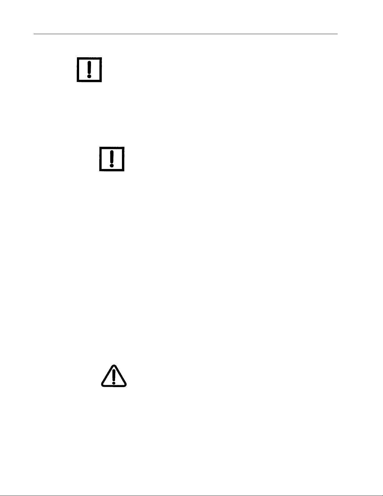
The SVI® II AP (Smart Valve Interface) is the next generation of Masoneilan’s intelligent
digital valve positioners. The SVI II AP is a high performance, digital valve positioner that
combines a local display with remote communication and diagnostic capabilities. The SVI II
AP offers a multitude of options that fulfills the broadest range of applications. It also
communicates using the HART
®
protocol.
1
An optional pushbutton and LCD display enables local operations of calibration and
configuration functions. Remote operations can be performed with ValVue
HART Registered host interface that has been pre-loaded with the Device Description file
(DD) for SVI II AP.
The SVI II AP is provided with Masoneilan’s ValVue software. The user-friendly interface
facilitates the setup and diagnostics of a control valve.
®
software or any
Figure 1 SVI II AP
1

Dresser Masoneilan
ValVue Software
Not only does V alVue provide the ability to quickly and easily set up the SVI II AP you can
also monitor operation and diagnose problems with ValVue’s advanced diagnostic
capabilities.
ValVue Lite
ValVue Lite software is shipped with each SVI II AP for positioner calibration and
configuration. ValVue Lite software is freeware and does not require any registration. It
provides functions to properly set up and start up an SVI II AP positioner on any type of
control valve.
System Requirements
ValVue Lite ru ns on IBM comp atible co mputers. Minimum requirement s fo r all versions o f
ValVue software are Windows 2000, XP, 64 MB RAM, serial or USB port connected to a
®
HART
modem, and a CD-ROM drive.
SVI II AP Instruction Manual
ValVue Trial Version
8/10
DRAFT 6/
The SVI II AP is provided with a trial version of ValVue. For 60 days after the initial
installation, ValVue provides the capability of configuring, calibrating, diagnosing, cloning ,
trending and much more. After the 60 trial period ValVue must be registered for use.
ValVue is a user-friendly, graphical interface that allows an efficient setup of an SVI II AP
mounted on any control valve assembly. Because of its
What-You-See-Is-What-You-Get (WYSIWYG) software environment, it is a very simple
user-interface.
ValVue functionality includes:
q Setup Wizard q Remote display of valve position, actuator pressure(s) q Set calibration parameters q Set configuration parameters q Monitor status⁄error indicators q Input/Output configuration q Remote calibration of the SVI II AP q Remote configuration of the SVI II AP q Remote operation of the SVI II AP q Backup and restore configuration (clone device) q Trend setpoint, valve position, actuator pressure
2

Operational Overview
q Display comparative test results (full version only) q Perform diagnostic test procedures (full version only)
Advanced and Online Diagnostics
The SVI II AP offers various levels of control valve diagnostics. Up to five pressure
sensors that detect circuit board temperature, loop current, and reference voltage, are
available for diagnostics.
For more details on the use of V alVue software, refer to the ValV ue User’s Guide. Contact
Masoneilan or your local Masoneilan representative to obtain licensing information.
Contact Masoneilan
For the most recent software visit our SVI II AP web site at: www.masoneilan.com
Operational Overview
The SVI II AP is a smart electro-pneumatic positioner that receives a
4 - 20 mA electrical position setpoint signal from the controller and compares the position
setpoint input signal to the valve position feedback sensor. The difference between the
position setpoint and position feedback is analyzed by the position control algorithm that
sets a servo signal for the I/P converter. The output pressure of the I/P is amplified by a
pneumatic relay that drives the actuator. Once the error between the setpoint and the
valve position feedback is within range, no other correction is applied to the servo signal
in order to maintain valve position.
Introduction
The local explosion proof LCD/Buttons (if equipped) display provides configuration or
calibration mode in all operating environments. The limit switch⁄transmitter options board
provides contact outputs that are software configurable, and an analog (4 - 20 mA)
position feedback.
SVI II AP Features
The SVI II AP Positioner (see Figure 1 on page -1) is suitable for installation indoors or
outdoors, and in a corrosive industrial or marine environment and is equipped with the
following features:
q Extreme Accuracy q Extreme Reliability q Extreme Digital Precision q Automated Valve Commissioning q Precise, Quick, Responsive Control of Valve Position q Valve Position Autotuning
DRAFT 6/8/10
3

Dresser Masoneilan
q One Model for Rotary or Reciprocating Valves q Local Operation⁄calibration⁄configuration with Optional Flameproof Push Buttons
and LCD Digital Display
q Compatible with Air-to-Close or Air-to-Open Actuators q Non-contact Magnet Coupled (Hall Effect) Position Sensing for Rotary and
Reciprocating Control Valves
q Sealed Housing with No Moving Shafts, No Shaft Penetration, and Fully Potted
Electronics
q Uniform Hazardous Area Approvals for ATEX, CSA, and FM with Other Approvals
Available Upon Request
q Local, On-line Diagnostic Condition Monitor: Total Stem Travel, Number of Valve
Cycles, Predictive Maintenance Data
q Advanced Valve Diagnostics with ValVue Software and the Pressure Sensor
Option
q User-adjustable Response Times
SVI II AP Instruction Manual
q Split-range Capability
8/10
q Configurable High and Low Position Limits q Characterize Stroke
q Linear q Equal Percentage 50:1 q Equal Percentage 30:1 q Quick Opening
DRAFT 6/
q 11 Point Custom Characterization
q Camflex q Optimized Performance Regardless of Actuator Size q Linearity Compensation for Actuator Linkages with
ValVue Software
q User Configurable Tight Shutoff at Adjustable Input Signal q HART Compatible q HART Remote Operation Calibration Configuration Diagnostics Using ValVue
software or a HART Handheld Communicator, HH375 and any HART Compatible
Host
®
Percentage
q Single or Double Acting
4

Available Options
Available Options
Some of the options available for the SVI II AP are listed below:
q Remote Position Sensor q Two Contact Outputs User Linked to Various Status and Alarm Flags q Offshore Construction - Stainless Steel Housing and Components q Pushbutton Display
About This Manual
The SVI II AP Instruction Manual is intended to help a Field Engineer install, setup, and
calibrate an SVI II AP in the most efficient manner possible. This manual also provides
in-depth information on SVI II AP software, digital interfaces, operation, intrinsic safety
configurations, and specifications. If you experience problems that are not documented
in this guide contact Masoneilan or your local Masoneilan representative. Sales offices
are listed on the back cover of this manual.
Introduction
Conventions Used in This Manual
Conventions used in this manual are as follows:
q Uppercase, italicized letters are used when referencing a term used in the SVI II
AP display window. For example, when indicating the term mode, as in setup
mode, and referring to the display/software operation the convention is to spell
mode is all uppercase letters: MODE.
q Italics is used for emphasis on important items. q Fields where data is entered or user-entered data is italicized. q Actions performed on buttons, checkboxes, etc. appear bolded. For example: Click
Done.
NOTE Indicates important facts and conditions.
CAUTION Indicates a potentially hazardous situation, which if not
avoided could result in property damage or data loss.
DRAFT 6/8/10
WARNING Indicates a potentially hazardous situation, which if not
avoided could result in death or serious injury.
5

SVI II AP Instruction Manual
8/10
DRAFT 6/
This page intentionally left blank.

Installation and Set Up
NOTE
Overview
The SVI II AP (Smart Valve Interface - see Figure 2 on page 8) is the next generation of
Masoneilan’s intelligent digital valve positioners. The SVI II AP is a high performance, digital
valve positioner that combines a local display with remote communication and diagnostic
capabilities. The SVI II AP is available with a variety of options to fulfill diverse applications
and it communicates using the HART
Prior to beginning the installation process revie w the safety information on page iii at the beginning of this manual.
®
protocol.
2
7
Dresser Masoneilan
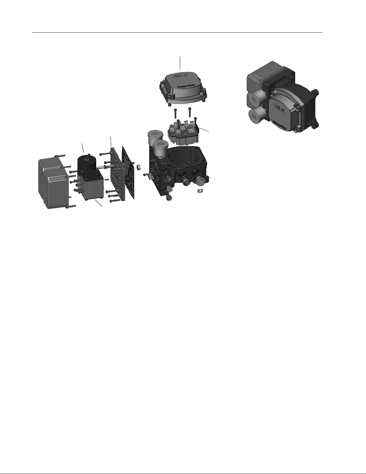
SVI II AP Cover
SVI II AP Assembled
Electronics
Module
Pneumatic Train and
Cover (I/P Module,
Relay)
Relay
I/P
Manifold
SVI II AP Instruction Manual
8/10
DRAFT 6/
Figure 2 SVI II AP Components
8

SVI II AP Dimensions and Weights
122.55 mm
34.00 mm
1.90 mm
38.10 mm
47.58 mm
74.97 mm
96.56 mm
34.00 mm23.00 mm
(74.97 mm)
203.93 mm
8.03 in
4.825 in
4.93 in
125.33 mm
1.34 in
0.075 in
(1.90 mm)
(0.075 in)
4.19 in
106.36 mm
2.1 in
53.18 mm
1.5 in
1.87 in
2.95 in
3.8 in
145.37 mm
5.72 in
1.34 in
.90 in
(2.95 in)
Weight Standard - 7.4 lbs (3.357 kg)
Center of Gravity
Weight Stainless Steel - 16 lbs/ 7.257 kg
SVI II AP Dimensions and Weights
Figure 3 illustrates the dimensions and weight of the SVI II AP.
Installation and Set
DRAFT 6/8/10
Figure 3 SVI II AP Dimensions
9

Dresser Masoneilan
Pre-Installation Issues
Storage
If the SVI II AP is stored for a long duration, you must keep the housing sealed against
weather, fluids, particles, and insects. To prevent damage to the SVI II AP:
q Use the plugs provided with shipment to plug the ¼ NPT air connections, on the
positioner and on the air filter regulator set.
q Do not allow standing water to accumulate. q Observe storage temperature requirements.
Unpacking
Exercise care when unpacking the control valve and its mounted accessories. The SVI II
AP container includes a CD-ROM with ValVue Lite, ValVue Trial Version, and manuals.
Installation Steps
SVI II AP Instruction Manual
If you experience problems that are not documented in this guide call Masoneilan or your
8/10
Step No. Procedure Reference
DRAFT 6/
1 Attach mounting bracket to the actuator. See page 13 for rotary valve and
2 Install the SVI II AP magnetic assembly (rotary valves
3 Assemble the SVI II AP on the bracket that is
4 Install the Remote Position Sensor, if necessary. See page 23 for instructions.
local Masoneilan representative. Sales offices are listed on the last page of this
document.
The steps necessary to complete the SVI II AP installation and software setup are
outlined in Table 1.
Table 1 SVI II AP Installation Steps
page 17 for reciprocating valve
instructions.
See page 17 for instructions.
only).
See page 13 for rotary valve and
mounted to the valve actuator.
page 17 for reciprocating valve
instructions.
5 Connect the pneumatic tubing to the SVI II AP. See page 29 for instructions.
6 Connect the air supply to the SVI II AP. See page 32 for instructions.
10
Installation Notes
Installation and Set
Table 1 SVI II AP Installation Steps (Continued)
Step No. Procedure Reference
7 Connect the positioner to the HART Control Loop
segment by installing the SVI II AP wiring.
8 Configure/Calibrate using LCD Pushbutton display See page 67 for instructions
Configure/Calibrate using a Hart Hand Held
Communicator.
Configure/Calibrate using ValVue See page 77 for instructions.
WARNING Failure to adhere to the requirements listed in this manual can
See page 33 for instructions.
See page 75 for instructions
cause loss of life and property.
WARNING Before installing, using, or carrying out any maintenance t asks
associated with this instrument, READ THE INSTRUCTIONS
CAREFULLY.
Installation Notes
q The installation must comply with local and national regulations concerning the
compressed air supply and SVI II AP instrument.
q Installation and maintenance must be performed only b y qualified personnel. SVI II
AP repairs beyond the scope of this manual must be performed by Masoneilan.
q Area Classification, Protection Type, Temperature Class, Gas Group, and Ingress
protection must conform to the data indicated on the label.
q Wiring and conduit must conform to all local and national codes governing the
installation. Wiring must be rated for at least 85º C (185º F) or 5º C (41º F) above
max ambient, whichever is greater.
q Approved wire seals against ingress of water and dust are required and the 1/2"
NPT fittings must be sealed with tape or pipe dope in order to meet the highest
level of ingress protection.
DRAFT 6/8/10
11

Dresser Masoneilan
Before Powering Up
Before powering up the SVI II AP:
1. Verify th at the pneumatic connections and electronic cover screws are tightened. This is important to maintain the ingress protection level and the integrity of the flameproof enclosure.
2. If the installation is Intrinsically Safe, then check that the proper barriers are installed and the field wiring meets local and national codes for an IS installation.
3. If the installation is Non-Incendive, then check that all the electrical connections are to approved devices and wiring meets local and national codes.
4. Verify that the markings on the label are consistent with the application.
SVI II AP Instruction Manual
NOTE For Hazardous Location Installation information refer to
Section “Specifications and References”.
Mounting the Positioner
8/10
This guide provides installation instructions for mounting an SVI II AP on both rotary and
reciprocating actuated valves. The mounting process can be broken down into the
following:
q Attach the mounting bracket to the actuator. q Install the magnetic assembly (rotary only). q Assemble the SVI II AP on the mounting bracket.
DRAFT 6/
Necessary Precautions
To avoid injury or the process being affected when installing or replacing a positioner on a
control valve, ensure that:
q If the valve is located in a hazardous area make sure the area has been certified
as safe or that all electrical power to the area has been disconnected before
removing any covers or disconnecting any leads.
NOTE Mount the SVI II AP with the conduit connections down in
order to facilitate drainage of condensate from the conduit.
q Shut off air supply to the actuator and to any valve mounted equipment. q Ensure the valve is isolated from the process by either shutting off the process or
using bypass valves for isolation. Tag shutoff or bypass valves to guard against a
turn-on while work is in progress.
q Purge air from actuator and check that valve is in its unenergized position.
12

Filter Regulator and Tubing
Filter Regulator and Tubing
The use of a Masoneilan filter regulator with a 5-micron filter is recommended for the air
supply. Use 1⁄4" (6.35 mm) minimum tubing between filter regulator, SVI II AP and the
actuator, with 3⁄8" (9.53 mm) used for larger actuators. Use a soft setting anaerobic
hydraulic seal such as Loctite Hydraulic Seal 542 for sealing the pneumatic pipe threads.
Follow manufacturers instructions.
NOTE Maximum allowable air supply pressure to the SVI II AP
varies according to actuator and valve size and type. See
pressure drop tables in valve specification sheets to
determine correct positioner supply pressure. Minimum
supply pressure should be 5 to 10 psi
(.345 bar - .69 bar) (34.485 - 68.97 kPa) above maximum
spring pressure.
Mounting the SVI II AP on Rotary Valves
Installation and Set
This procedure is used to mount the SVI II AP on rotary control valves that have less than
60° rotation, such as a Camflex
60° refer to “Rotary - 90°” on page 16
Required Tools
The following tools are needed to complete the rotary valve installation:
q 3⁄16" Hex Key with tee handle q 5⁄32" Hex Key q 3 mm, 4mm, 5mm Hex Key q 7⁄16" Wrench
To mount the SVI II AP:
1. Attach the SVI II AP rotary mounting bracket t o the valve a ctuator using two (2) 5⁄16 -
18 UNC flat-head cap screws. Mount the SVI II AP as shown in Figure 5 on page 15,
ATO or in Figure 6 on page 15, ATC. In the preferred mounting position, the long end
of the mounting bracket is on your left when facing the actuator, for any position of the
valve and actuator.
®
or a V arimax
®
. For valves that have rotation greater than
DRAFT 6/8/10
2. Bolt the extension shaft to the valve position take-of f shaft using a 1⁄4 - 28 UNF socket
flathead screw . Secure the machine screw holding the extension shaf t with a torque of
144 in-lbs (16.269 N-m).
3. Upon internal valve pressure the thrust shaft is pushed out to the mechanical stops,
usually a thrust bearing. On valves where the valve position take-off is mounted
directly on the end of the plug shaft, a Camflex for example, the shaft must be bearing
on its stop to properly set up the SVI II AP positioner. During hydrostatic testing the
shaft is thrust to its stop and a normally tightened packing retains it in that position.
13
Dresser Masoneilan
4. On vacuum service, the valve shaft can be drawn into the body by the vacuum acting
on the shaft, but the magnetic coupling must be assembled flush with the mounting
bracket with the shaft pulled fully out to it s thrust bearing. Check that the end play from
the vacuum position to the fully extended position is less than 0.06 in. (1.524 mm)
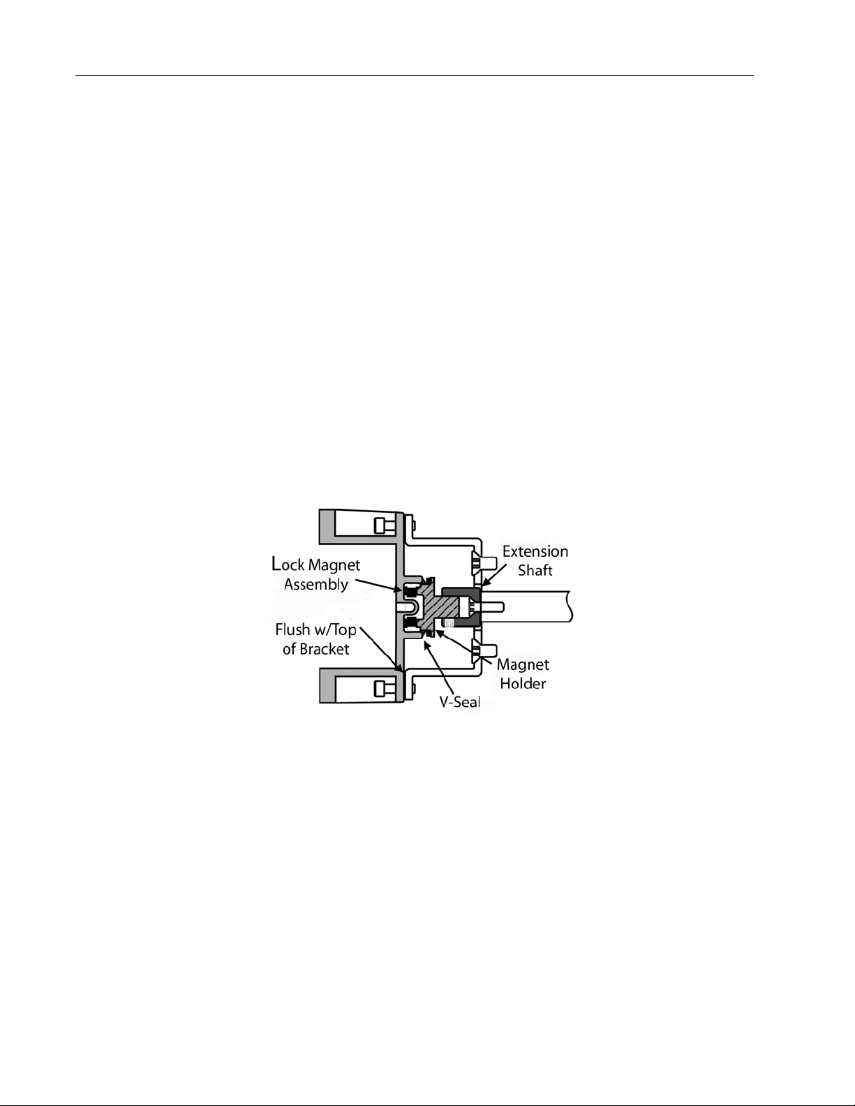
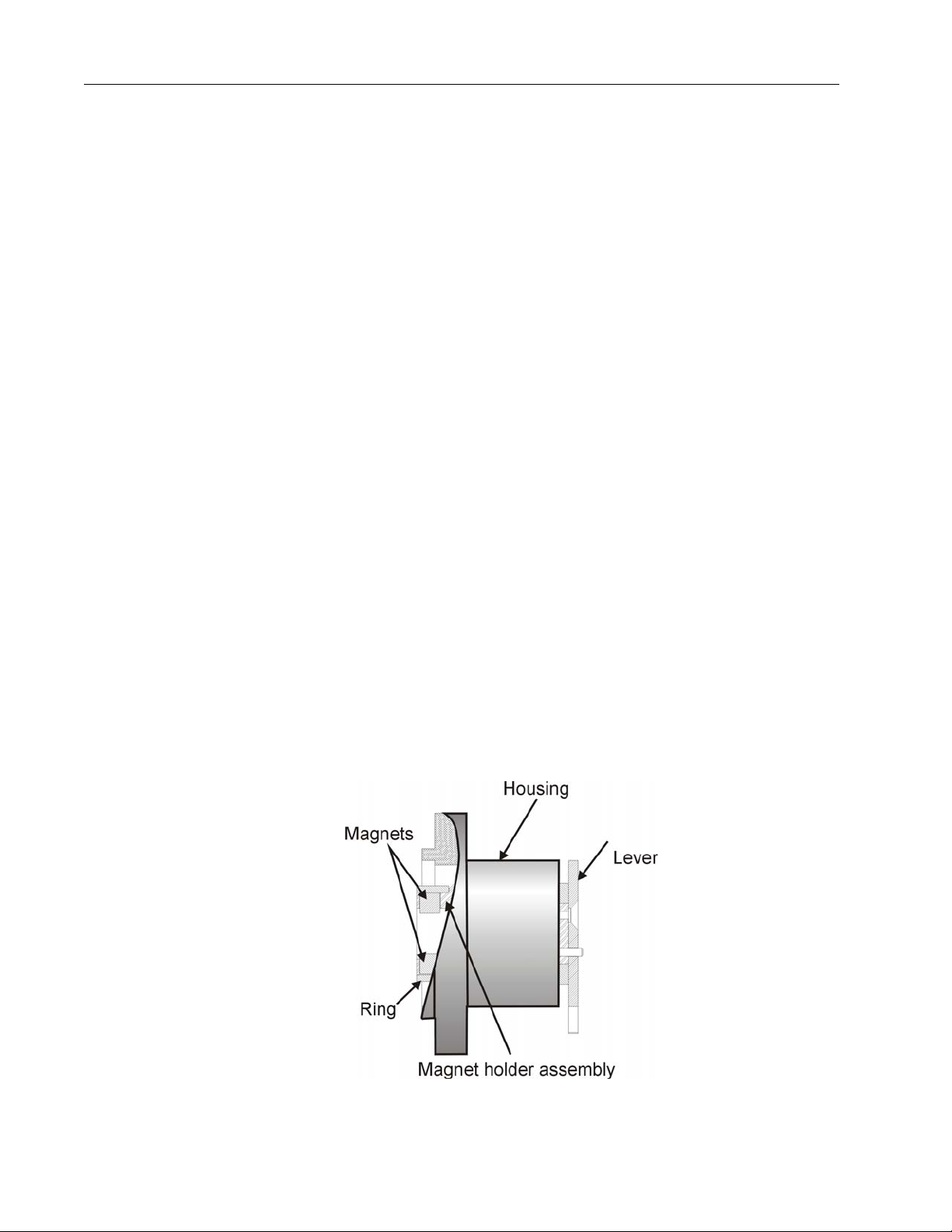
5. Slide the magnet holder into the extension shaft. The location of the magnet s is in the ring of the magnet holder. The magnetic axis is the imaginary line through the center of both magnets.
6. Rotate the magnet holder so that the magnet axis is vertical when the valve is in the closed position. See Figure 5 and Figure 6.
7. Align the end of the magnet holder flush with the end of the mounting bracket. Secure the magnet holder with two M6 set screws.
8. Slide the V-Seal over the magnet holder.
9. Secure the SVI II AP onto the mounting bracket using four M6 x 20 mm Socket Head Cap Screws.
10. Ensure no interference exists with the position sensor protrusion.
11. Ensure that the V-Seal makes contact with the skirt around the position sensor protrusion on SVI II AP housing.
SVI II AP Instruction Manual
8/10
DRAFT 6/
Figure 4 Camflex with Mounting Bracket (Side View)
14

Required Tools
Installation and Set
Figure 5 Camflex ATO Mounting (Front View)
Figure 6 Mounting Bracket on Air-to-Close Actuator
15
DRAFT 6/8/10
Dresser Masoneilan
SVI II AP Instruction Manual
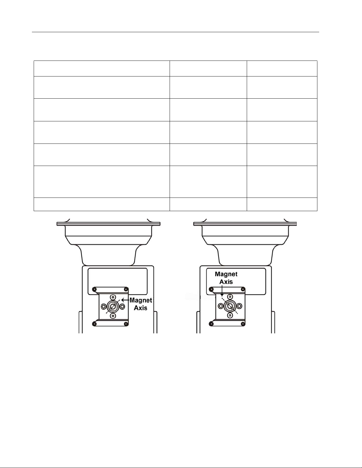
Table 2 Magnet Orientation on Rotary Actuators
Rotary Actuator Type Magnet Setting - ATO Magnet Setting - ATC
Camflex Actuator is energized __ Magnet Axis is Vertical
Figure 6
Camflex Actuator is de-energized Magnet Axis is Vertical
Figure 5
Varimax
Actuator is energized
Varimax
Actuator is de-energized
Model 33 in clockwise to open valve
Actuator is de-energized
(36000 Series Control Ball, 37000 MiniTork
Double acting cylinders at mid-travel Magnet Axis Vertical Magnet Axis Vertical
®
®
)
__ Magnet Axis is Vertical
Magnet Axis is Vertical __
Magnet axis 45° to right of
vertical position in Figure 7
__
Magnet axis 45° to right
of vertical
8/10
DRAFT 6/
Rotary - 90°
For actuators with 60 to 120° rotation, follow the instructions in “Mounting the SVI II AP
on Rotary Valves” on page 13 except mount the magnet at plus or minus 45° while the
actuator de-energized as shown in Figure 7 on page 16.
Figure 7 Model 33 Actuator
16

Magnet Orientation on Rotary
Magnet Orientation on Rotary Valve Shafts
The same mounting hardware is used for Models 35, 30 actuators. For each actuator type
the magnetic coupling must be properly oriented to the active sensing angle of the
positioners Hall Effect sensor . The active range of the Hall-Effect sensor is plus⁄minus 70°
from the null magnet axis. If the total valve travel is less than 60°, allowing a margin for
tolerances, the best accuracy is achieved by mounting the magnet with the axis vertical in
the valve-closed position. Note the location of the magnets in the ring of the magnet
holder. The axis of the magnets is the line through the centers of both magnets. Mount
the magnet holder with the magnet axis vertical on the 35, 30 when the valve is clo sed. If
travel of the valve exceeds 60°, the magnet must be assembled to the rotary valve shaft
so that the magnet axis is vertical when the valve is at mid-scale.
Dismantling the SVI II AP from Rotary Valves
WARNING Before carrying out any work on the device, power off the
instrument or make sure that the device’s location conditions
for potentially explosive atmosphere permit the safe opening
of the cover.
Installation and Set
To remove the SVI II AP positioner from a rotary valve perform Steps 1 - 8 on page
page 10 in reverse.
Mounting the SVI II AP on Reciprocating Valves
This section describes the procedure for mounting the SVI II AP on Reciprocating Valves
(using Masoneilan’s 87⁄88 Multi-Sp ring actuators as an example).
Tools required:
q 7⁄16" Combination Wrench (2 required) q 3⁄8" Combination Wrench q 1⁄2" Combination Wrench q Phillips Head Screw Driver q 5 mm Hex Key Wrench
Mounting the SVI II AP on a Reciprocating Actuator
1. Ensure that the lever is pinned to the magnet assembly and held securely by an M5
flat head screw to ensure that the magnet axis is vertical when the lever is in the valve
closed position. Tighten the lever screw securely.
DRAFT 6/8/10
2. Mount the SVI II AP reciprocating mounting bracket to the actuator using two (2) 5⁄16
- 18 UNC cap screws. The mounting location of the bracket depends on the size and
stroke of the actuator. Refer to Figure 9 on page 19 and Figure 3 on page 19.
17
Dresser Masoneilan
3. Select mounting hole A, B, C or D for the stroke of the valve. For example, hole B is
shown in Figure 10 on page 19 for a size 10 actuator with 1.0" stroke. Unless
otherwise specified, the SVI II AP mounting assumes that th e actuator is in the normal
upright position. The mounting hole in the slotted opening of the mounting bracket
must be left when facing the actuator, with the actuator in the upright position.
4. Thread the take-off rod to the actuator stem connector . Refe r to Figure 11 on pa ge 20. Ensure that the travel pointer located on the coupling is correctly positioned.
5. Attach the right hand threaded rod end to the SVI II AP lever using a 1⁄4 - 20 x 1" cap
screw and nut as shown. The lever hole position to be used depends upon the
specific valve stroke. Refer to Figure 10 on page 19 and the Reciprocating Valve
Linkage Selection, Table 3 on page 19.
6. Thread the right hand lock nut and turnbuckle onto the right hand rod end approximately two turns. Turnbuckle length is a function of actuator size. (Refer to Table 3 on page 19.)
7. Secure the magnet housing assembly, including the lever and right hand rod end, to the bracket using four M5 X 10 mm flat head screws.
SVI II AP Instruction Manual
8. Attach the left hand threaded rod end to the take-off rod with 1⁄4 - 20 UNC nut and thread the left hand lock nut onto the rod end.
8/10
DRAFT 6/
9. Move the valve to its closed position. For air to extend, this requires using air pressure in the actuator to fully stroke the actuator . For air to retract, actuators vent the actuator of air pressure.
10. Thread the turnbuckle onto the left hand threaded rod end. Refer to Figure 11 on page 20.
11. Adjust the turnbuckle until the hole in the SVI II AP lever is aligned with the indicating hole in the bracket. Tighten both turnbuckle lock nuts. (See Figure 9 on page 19.)
12. Mount the SVI II AP to the bracket and secure with four M6 socket head cap screws.
Figure 8 Magnet Holder for Reciprocating Valves
18
 Loading...