

Dresser Masoneilan Camflex II 35002 Series Instructions Manual
Masoneilan®
Instruction N°
Series 35002
Camflex II Valve Instructions
Includes rolling diaphragm, and manual actuator
EF 5000 E
01/2004

Instruction No EF 5000 E
01/2004
Summary
1. - INTRODUCTION ...................................... ... .. 3
2. - GENERAL .......................................... ... ... ... .. 3
3. - PRINCIPLE OF OPERATION ....................... 4
4. - UNPACKING ................................................. 5
5. - INSTALLATION........ ... ... ... .... ... ... ... .... ........... 5
6. - AIR SUPPLY PIPING .................................... 5
7. - PLACING IN SERVICE ................................. 5
8. - DISASSEMBLY..................................... ... ... .. 6
8.1 - ACTUATOR REMOVAL FROM BODY S/A...........6
8.2 - ACTUATOR COMPLETE DISASSEMBLY............7
8.3 - VALVE BODY.........................................................7
9. - MAINTENANCE .......................................... .. 9
9.1 - SPRING DIAPHRAGM REPLACEMENT...............9
9.2 - BODY S/A INTERNAL PARTS ............................10
9.3 - YOKE ASSEMBLY...............................................11
10. - REASSEMBLY PROCEDURES.................. 11
10.1 - SPRING DIAPHRAGM ACTUATOR....................11
10.2 - SPRING DIAPHRAGM ACTUATOR ON
BODY S/A.............................................................11
10.3 - HANDWHEEL REASSEMBLY.............................12
10.4 - LIMIT STOP REASSEMBLY................................12
10.5 - VALVE BODY REASSEMBLY.............................12
10.6 - SEAT RING ALIGNMENT ....................................13
10.7 - DVD PLATE REASSEMBLY................................14
11. - ACTUATOR STEM ADJUSTMENT ............ 14
12. - CHANGING BODY POSITION.................... 16
13. - CHANGING ACTUATOR ACTION ............. 16
14. - MANUAL ACTUATOR OPTION ................. 17
14.1 - DISASSEMBLY PROCEDURE ............................17
14.2 - MAINTENANCE ...................................................17
14.3 - REASSEMBLY PROCEDURE .............................17
2
1. Introduction
Instruction No EF 5000 E
01/2004
The following instructions are designed to assist
maintenance personnel in performing most of the
maintenance required on the Camflex® II valve and
if followed carefully will reduce maintenance time.
Masoneilan has highly skilled Service Engineers
available for start-up, maintenance and repair of our
valves and component parts. In addition, regularly
scheduled training programs are conducted to train
customer service and instrumentation personnel in
the operation, maintenance and application of our
control valves and instruments. Arrangements for
these services can be made through your
Masoneilan Representative or District Office. When
performing maintenance use only Masoneilan
replacement parts. Parts are obtainable through
your local Masoneilan Representative or District
Office. When ordering parts always include Model
and Serial Number of the unit being repaired.
2. General
These installation and maintenance instructions
apply to 1" through 12" sizes, all available ANSI
ratings, and pneumatic actuators. The model
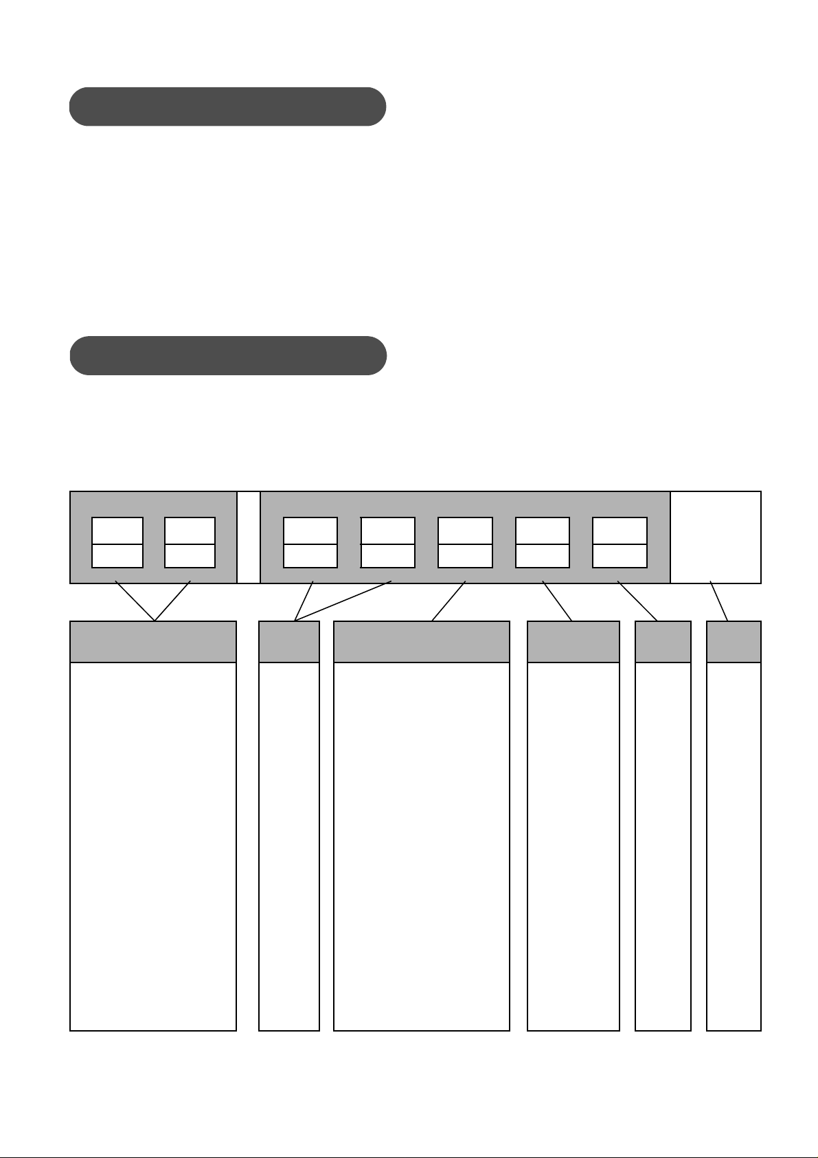
35002 Series Body Numbering System
Actuator Assembly digits Body Assembly Digits
st
1
nd
2
st
1
3 5 2
nd
2
number, size and rating of the valve are shown on
the serial plate. Refer to figure 1 to identify the valve
mode.
rd
3
th
4
th
5
SB
Actuator Type
20 Manual Actuator
35 Spring-opposed
rolling-diaphragm
(1) optional, Camflex with separable bonnet.
Body
Series
35 valve
Actuator Mounting
1. Parallel to pipe line,
valve closes on stem
extension
2. Parallel to pipe line,
valve opens on stem
extension
3. Perpendicular to pipe line,
valve closes on stem
extension
4. Perpendicular to pipe line,
valve opens on stem
extension
5. Parallel to pipe line,
valve closes on stem
extension
6. Parallel to pipe line,
valve opens on stem
extension
7. Perpendicular to pipe line,
valve closes on stem
extension
8. Perpendicular to pipe line,
valve opens on stem
extension
Figure 1
Seat
Design
1. Metal seat
2. Soft seat
3. Metal seat
Lo-dB
4. Soft seat
Lo-dB
5. Ceramic
TRIM
Design
Series
2SB (1)
Design
3
Instruction No EF 5000 E
01/2004
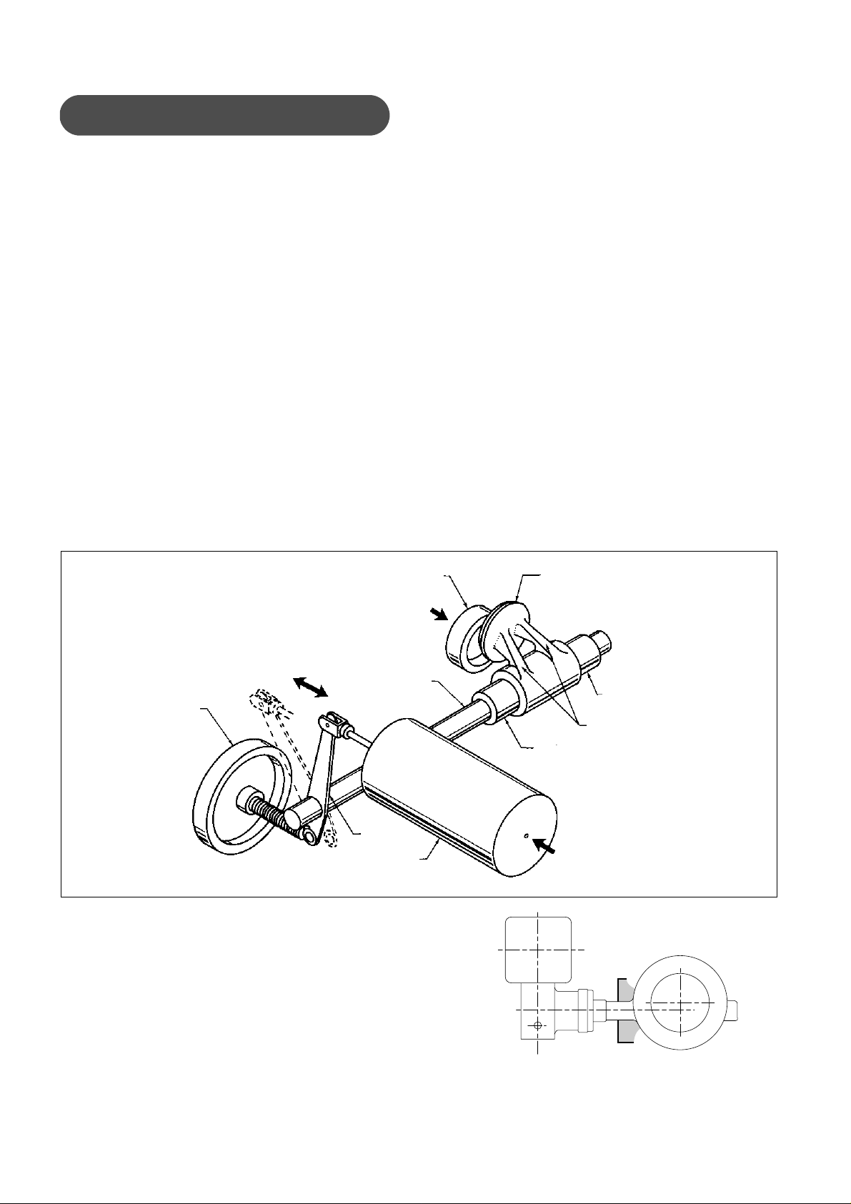
3. Principle of operation
The concept of the Camflex® II valve is based on an
eccentrically rotating spherical plug contained in a
free flow design ANSI Class 600 body. The plug
seating surface is joined by flexible arms to a hub
which slides onto a rotating shaft. The plug is free to
center itself along the axis of the shaft. A positive
seal between plug and seat is achieved by elastic
deformation of the plug arms. The chamfered seat
ring is fixed in the valve body by a threaded retainer.
The plug and shaft are rotated through an angle of
50° by a lever linked to a powerful spring-opposed
rolling diaphragm actuator.
The solid disk-type handwheel and locking lever,
provided as standard features on the Camflex® II
valve and are mounted on the yoke opposite the
actuator. The handwheel may be used as a manual
actuator or as a limit stop. A threaded hole in the
opposite side of the yoke accommodates a cap
screw and locknut which may be inserted as a limit
stop in the other direction, or in combination with the
handwheel to lock the valve in a selected position.
Figure 2
Seat Ring
The handwheel on Camflex® II is designed to be
used for emergency action only.
The actuator is generally mounted with air-loading to
counter the dynamic torque on the plug. In figure 2
the flow direction tends to open the plug and the
actuator is oriented to close it with increasing air
pressure. The actuator spring fo rce assists plu g offbalance forces to open the valve on air failure. If the
valve is to close on air failure, the body would be
turned around in the line so that flow tends to close
the plug and the actuator position would be reversed.
The Camflex® II valve has a modified linear flow
characteristic, which is the same in either flow
direction. It can be easily transformed to an equal
percentage when equipping the valve with a
positioner 4700 series, 8000 series, SVI (Smart
Valve Interface) or FVP.Reduced TRIM factors 0.4
and 0.6 are available on all sizes. The flow capacity
of a 0.4 factor is 40% of the nominal capacity of the
valve and it is 60% for the 0.6 factor. Factors 0.1 and
0.2 are available on the DN 25 (1") valve.
Plug
Fluid flow
Handwheel
Lever
Actuator
The ability of the Camflex® II valve to handle a wide
range of process fluid temperatures is due to the
long integrally cast bonnet. This affords ample
radiation surface to normalise the packing
temperature. Therefore, with self-lubricating TFE
Aramid fiber packing, the valve handles
temperatures from - 200°C to + 400°C (-320°F to
+750°F). When insulating the valve, do not insulate
the body neck (see figure 3).
Shaft
Guide Bushing
Flexible arms
Guide Bushing
Air
Figure 3
4

4. Unpacking
Care must be exercised when unpacking the valve to
prevent damage to the accessories and component
parts. Should any problems arise, contact the
Masoneilan Representative or District Office.
Note: For ease of shipment and to prevent damage,
valves equipped with the spring diaphragm actuator
are shipped with the handwheel unassembled. Refer
to section 10.3 for handwheel assembly procedures.
Instruction No EF 5000 E
01/2004
E. If the valve is to be installed in a horizontal
position, install the lower flange bolting to
provide a cradle, which will help support, the
valve while installing the remaining bolts.
F. Place the valve in the line.
G. Select and install correct gaskets.
Note: Spiral wound gaskets, suitable for service
conditions are recommended.
H. Insert remaining flange bolting insuring that the
bolts align with the special bosses on the body,
which assure the valve is centered in the line and
also prevent rotation.
5. Installation
The Camflex® II valve has been assemb led at the
factory in accordance with specify instructions
concerning flow direction and actuator mode. The
valve must be installed so that the controlled
substance will flow through the valve in the direction
indicated by the flow arrow (25), which is loca ted on
the upper part of the valve body neck. The valve
actuator should be installed so the actuator is above
the centerline of the shaft. To install the valve in the
line, proceed as follows:
Caution: Any change in flow direction or
actuator mode must be accomplished as
outlined. In this instruction otherwise
equipment malfunction could result.
A. Check the model number on the serial plate (56)
against the numbering System described in
figure 1 to determine the valve mode.
B. Clean piping and valve of ail foreign material
such as welding chips, scale, oil, grease or dirt.
Gasket surfaces should be thoroughly cleaned to
insure leak proof connections.
C. To allow for in-line inspection, maintenance or
removal of the valve without service interruption,
provide a manually operated stop valve on each
side of the Camflex® II valve with a manually
operated throttling valve mounted in the by-pass
line.
Note: If a flanged Camflex® II is being installed
and the distance between flanges is established
by ANSI or DIN, spool pieces (spacers) are
inserted between the line flange and the valve
body flange. Gaskets and valve bolting are then
installed and torqued using standard flange and
line bolting criteria.
Note: For certain flange standards, through
bolting is not possible because of the valve body
neck or bonnet. To accommodate flange bolting,
guide arms with threaded holes or slots are
provided on the valve body to receive flange
bolts (refer to figure 22).
I. Tighten flange bolts e ve nly and firmly.
Cantion: If the valve is to be insulated, do not
insulate the valve body neck.
Note: If the valve is equipped with manual
handwheel, it may now be placed in service.
6. Air Supply Piping
Air is supplied to the actuator through the 1/4" NPT
tapped connection in the diaphragm case. Refer to
figure 14 to determine the correct supply pressure
and tubing size, then connect air supply piping.
Caution: Do not exceed maximum air
pressure indicated. Personal injury and
equipment malfunction could result.
Note: When the valve is equipped with regulators or
other accessories supplied by Masoneilan, only
connections to those accessories are required since
the piping to the actuator is connected at the factory.
Some valves equipped with electrical accessories
will require appropriate wiring. Refer to
manufacturer's instructions for correct wiring
information.
7. Placing in Service
D. For flangeless valves, refer to figure 23 and
determine the correct size and quantity of bolts
to be used for the valve and flange rating.
With the valve properly installed in the line and all air
or electrical service connected, it is recommended
5

Instruction No EF 5000 E
01/2004
that the valve be run through one cycle to insure
proper functioning. Proceed as follows:
A. Back off the handwheel (53) so that it will not
interfere with the operation of the valve and
tighten the handwheel lock (52).
Note: If the valve is equipped with the optional
limit stop (77), it should also be backed off to
prevent interference with the operation of the
valve.
B. Apply correct air pressure to the actuator.
Note: Valve should function smoothly and with
maximum pressure, the valve indicator (6)
should show full open or full close depending on
valve mode.
C. Relieve air pressure and return valve to normal
mode.
D. Gradually open process lines to place the valve
in service.
E. Check for leaks. Repair as required.
Caution: Always insure process pressure, a
pressure and electrical service are off and the
valve is isolated and relieved of pressure
before performing maintenance on the valve.
F. If desired, the handwheel may be used as a limit
stop. Set in desired position and lock.
G. If the optional limit stop (77) is used, set and
tighten locknut.
8. Disassembly
orientation and the actuator to yoke orientation be
marked in relation to each other. This will simplify
reassembly.
A. If required, remove the valve from the line.
B. Remove rear cover (29) and front cover (32) by
removing the two cover screws (30).
C. Remove bottom cover (11) and spring barrel
boss cover (58).
D. Remove indicator (88) by removing the two
screws (89).
E. Loosen handwheel lock (52) and turn handwhe el
(53) so it does not interfere with the movement of
the lever (34).
Note: On valves supplied with the optional limit
stop, (figure 17) loosen nut (78) and back off the
limit stop screw (77) so it will not interfere with
the movement of the lever (34).
F. Connect an air line to the actuator supply port
and using a manual loading panel or regulated
air supply, apply enough air pressure to the
actuator so the lever will move to an intermediate
position.
Caution: Do not exceed pressure listed in
figure 14 for actuator used. Do not use
handwheel to move the lever.
Note: If the valve is to be reassembled using the
same orientation, it is recommended that the
yoke (33) and lever (34) alignment, in the clo sed
position, be marked to simplify reassembly and
alignment of the lever and shaft to insure proper
valve functioning. See figure 17.
8.1 ACTUATOR REMOVAL FROM
BODY S/A
(Refer to figure 16 and figure 17)
Maintenance required on the internal components of
the valve or re-orientation of the actuator and body,
requires that the actuator and yoke be removed from
the valve. On the 6", 7" and No 9 actuators, for ease
of handling and reassembly, it is recommended that
the spring barrel be removed from the yoke and then
the yoke separated from the valve body.
Caution: Prior to performing maintenance on
the valve, isolate the valve, vent the process
pressure and shut off supply and signal air
lines to the actuator.
Note: If the valve will be reassembled in the same
orientation, it is recommended that the body to yoke
G. Remove clevis pin clips (5).
H. Remove clevis pin (7).
I. Relieve air pressure from actuator enabling
clevis (35) to disengage from lever (34).
Note: If the valve is equipped with a positioner,
refer to the appropriate positioner instruction for
procedures on cam or lever removal. Then
proceed to step K.
J. Remove shaft cover (9) by removing cover
screw (10).
Caution: Depending on the size and weight of
the actuator. It is recommended that proper
lift and support procedures be utilised when
removing the spring barrel or yoke.
K. Insure spring barrel is properly supported.
6

Instruction No EF 5000 E
01/2004
L. Loosen and remove cap screws (36) and
lockwashers (37), then remove spring
barrel (38).
M. Loosen lever capscrew (49).
N. Loosen the stud nuts (94) and disengage the
packing flange.
O. Loose the stud nuts (27) to separate the actuator
from the body S/A.
Note: With body secure, grasp lever and yoke and
separate. Yoke, lever and packing flange are
removed at the same time. The yoke may have to be
struck with a soft face mallet to break it loose.
8.2 ACTUATOR COMPLETE
DISASSEMBLY
The spring diaphragm actuator used on the
Camflex® II valve was designed basically as a low
cost non-replaceable item and therefore
disassembly is not recommended. However, in
some instances and for emergency purposes,
disassembly may be required. Proceed as follows.
A. In case of 35000 SB (Separable Bonnet) before
continuing in D it is necessary to loose and
remove the nut 104 to separate the bonnet with
the packing and the packing follower (15) from
the body.
B. Remove packing follower (15).
C. Remove safety pin (16).
Caution: The purpose of the safety pin is to
prevent the shaft from being pushed out if the
yoke is removed while the valve is still
pressurised. The internal components of the
valve cannot be removed without first
removing the safety pin.
D. Pull on the shaft (19) to remove it.
Note: Difficulty is sometimes encountered when
removing the shaft from the plug mainly due to
an excessive accumulation of deposits between
the plug splines and the shaft. Applica tion of heat
to the plug shaft bore while using one of the
following methods will facilitate removal.
A. If the actuator is not removed from the body
proceed to the paragraph 9.1 A. to 9.1 L.
B. Loosen locknut (46) then remove the clevis (35)
and the locknut (46).
C. Loosen and remove capscrew (41) and remove
diaphragm case (42) and diaphragm (40).
D. Using a deep socket, loosen and remove locknut
(45) and washer (44).
E. Remove piston (43) and spring (39) and inspect
all components.
F. Proceed to section 10.2 for reassembly.
8.3 VALVE BODY (Refer to fig. 4 & 16)
Maintenance to the internal components required on
the Camflex® II Valve can normally be easily
determined since the seat ring and plug can be see n
once the valve is removed from the line. Although it
may be determined that the seat ring does not need
replacement, it must be noted that the new plug and
seat ring must be lapped thus requiring the
disassembly of the body. It is recommended that
both seat ring and plug be replaced if one or the
other is damaged due to service.
After the actuator has been removed from the body,
disassemble the valve using the following
procedure:
Caution: When using heating devices. Insure
that proper safety practices are observed.
Such items as the flammability and t oxicity o f
the controlled substance must be considered
and proper precautions taken.
If the shaft is not removed easily, replace the
lever (34) on the splined end of the shaft (19), tighten
the lever capscrew (49) and using a mallet, tap the
lever (34) as close to the shaft as possible and
remove the shaft (19).
Note: If the shaft cannot be removed by tapping the
tightened lever, figure 20 illustrates an alternative
method of removal. Using a pipe nipple of suitable
size and length and reversing the packing flange and
stud nuts as shown, the shaft may be jacked out of
the body. For larger valves the use of an additional
washer and nipple to assist in holding the tightened
Lever is recommended. The lever should be
tightened at a point where the hub on the lever is
flush with the end of the spline.
E. The components which should come out with the
shaft (19) are: the packing (17), packing box ring
(23 or 100), spacer tube (20) and upper guide
bushing (21).
Caution: Prior to performing maintenance on
the valve, isolate the valve, vent the process
pressure.
7
Instruction No EF 5000 E
01/2004
Note: The spacer tube (20) and upper guide
bushing (21) may remain in the body. They
should be removed. The spacer tube (20) can
only be removed by pulling it out the bonnet end
of the body. The upper guide bushing (21) may
be pushed through the body after removing the
plug or pulled through the bonnet end of the
body. On valves designed for use on slurry or
viscous service, the upper guide bushing ha s an
inner "O" ring (92) and an outer "O" ring (93) and
the lower guide bushing has inner "O" ring (95)
and outer "O" ring (96) (Refer to figure 4).
93
92
Figure 4 - Optional “O” ring arrangement
21 22 96
95
F. Remove the plug (4) through the end of the body
opposite the seat ring.
G. Remove the lower guide bushing (22).
Note: A groove is provided in the bushing for
prying out the bushing using a screwdriver. If the
bushing will be pried out it should be pried from
two sides to prevent jamming the bushing during
removal. If the bushing does not come out easily,
fill the bushing with grease, insert the shaft (19)
into the valve insuring that the machined portion
of the shaft starts into the lower guide bushing.
Using a soft faced mallet, strike the end of the
shaft lightly until the bushing is pushed out
partially. Remove the shaft and complete
removal of the bushing by prying out using the
groove provided.
Caution: Do not pry the bushing using the
seat for leverage. If the bushing cannot be
easily removed, proceed to section 8.3.1 and
remove the seat ring retainer and seat ring
then remove the bushing. Place a piece of
soft stock (brass, etc.) between the inner seat
shoulder and prying device to prevent
damage to the seat sealing area of the body.
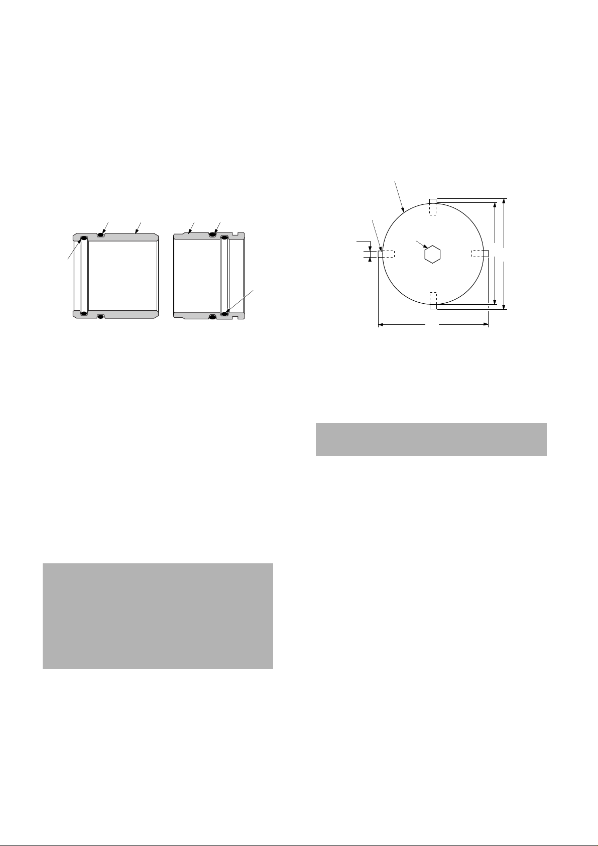
8.3.1 Seat Ring Removal (Refer to figure 16)
The following procedures outline the recommended
method for removing the seat ring retainer (3) with
the use of retainer wrenches. Masoneilan
manufactures and has available, for a nominal price,
seat ring retainer wrenches for the Camflex® II, 1"
through 4" sizes. lt is highly recommended that
wrenches be purchased or fabricated to facilitate
removal and reassembly of the seat ring (2) since
SPECIFIC TORQUES MUST BE ACHIEVED to
obtain tight shutoff and insure proper functioning of
the valve.
Figure 5 shows the recommended materials,
thickness and method of construction along with
specific dimensions to facilitate construction.
3/16" STEEL PLATE
WELDED
KEY
STOCK
B
WELDED
HEX NUT
A
A = O.D. Seat Ring Retainer
B = Width of slot in Retainer
C = I.D. of Seat Ring Retainer
Figure 5
C
A
A. Secure the valve body in a vise or appropriate
holding device with the seat ring facing up.
Care must be taken to avoid damage to the
gasket face on the valve body.
B. Place retainer wrench so it engages retainer
lugs.
C. Engage the retainer wrench with an impact
wrench or suitable wrench and loosen, then
remove retainer (3) by turning counterclockwise.
D. Lift out seat ring.
Note: In an emergency, drifts may be used to
remove the seat ring retainer. However, two
drifts should be used and placed in the slots 180°
apart and struck simultaneously.
8.3.2 DVD Removal (Refer to figure 16)
In case of Camflex® with the DVD option, model
number 35x3x or 35x4x, the DVD is installed in the
body, it is recommended to use the DVD wrenches to
remove this device (105). Masoneilan manufactures
and has available, for a nominal price, DVD wrenches
for the Camflex® II, 1" through 12" sizes. lt is highly
recommended that wrenches be purchased or
fabricated to facilitate removal and reassembly of the
DVD (105) since SPECIFIC TORQUES MUST BE
ACHIEVED to insure proper clamping of this DVD
plate.
8
 Loading...