

Dresser Consolidated 1900 Installation, Operation And Maintenance Manual

®
Consolidated
INST ALLATION, OPERA TION
AND MAINTENANCE MANUAL
®
Consolidated Safety Relief V alve
Type 1900
Design Options
Include:
Bellows
(-30),
O-Ring Seat
(DA),
Liquid Trim
(LA)
and
Industrial Valve Operation
Dresser Valve and Controls Division
Alexandria, Louisiana 71309-1430 (USA)
Thermodisc
®
(TD)
CON-2
Revised 7/97
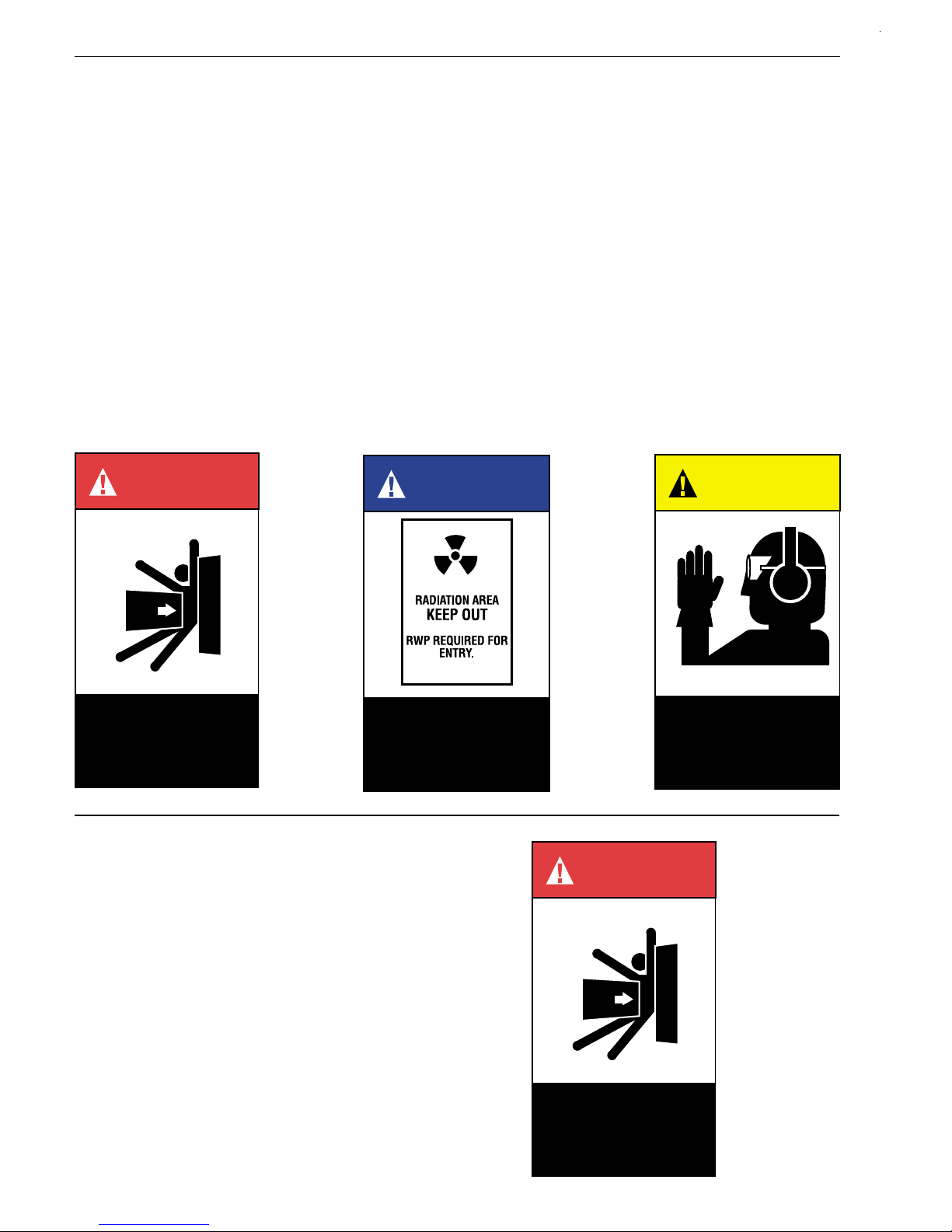
Product Safety Sign and Label System
Wear necessary
protective equipment
to prevent possible
injury .
CAUTION
If and when required, appropriate safety labels have
been included in the rectangular margin blocks
throughout this manual. Safety labels are vertically
oriented rectangles as shown in the
examples
by a narrow border. The panels can contain four
messages which communicate:
• The level of hazard seriousness.
• The nature of the hazard.
• The consequence of human, or product, interaction
with the hazard.
• The instructions, if necessary, on how to avoid the
hazard.
(below), consisting of three panels encircled
DANGER
representative
WARNING
The top panel of the format contains a signal word
(DANGER, WARNING, or CAUTION) which
communicates the level of hazard seriousness.
The center panel contains a pictorial which
communicates the nature of the hazard, and the possible
consequence of human or product interaction with the
hazard. In some instances of human hazards the pictorial
may, instead, depict what preventive measures to take,
such as wearing protective equipment.
The bottom panel may contain an instruction message
on how to avoid the hazard. In the case of human
hazard, this message may also contain a more precise
definition of the hazard, and the consequences of
human interaction with the hazard, than can be
communicated solely by the pictorial.
Do not remove bolts if
pressure in line, as this
will result in severe
personal injury or death.
Know nuclear health
physics procedures, if
applicable, to av oid
possible severe per
injury or death.
SAFETY ALERTS!
READ – UNDERSTAND – PRACTICE
1. DANGER: High temperature/pressure can
cause injury. Be sure all system pressure is absent
before repairing or removing valves.
2. DANGER: Don’t stand in front of valve
outlet when discharging. STAND CLEAR OF VALVE
to prevent exposure to trapped, corrosive media.
sonal
DANGER
3. DANGER: When inspecting a pressure
relief valve for leakage, BE VERY CAREFUL!
CON-2
Do not remove bolts if
pressure in line, as this
will result in severe
personal injury or death.

Page 1
Contents
Section Subject Page
I. Safety Alerts .................................................................................................................................. 2
II. Terminology for Safety Relief Valves ............................................................................................ 4
III. Introduction ................................................................................................................................... 5
IV. Design Features and Nomenclature .............................................................................................5
V. Handling, Storage and Pre-Installation ......................................................................................... 8
VI. Recommended Installation Practices ............................................................................................ 9
VII. Disassembly Instructions .............................................................................................................. 12
VIII. Cleaning ........................................................................................................................................ 14
IX. Parts Inspection ............................................................................................................................ 14
X. Maintenance Instructions .............................................................................................................. 22
XI. Reassembly................................................................................................................................... 29
XII. Setting and Testing ....................................................................................................................... 35
XIII. Hydrostatic Testing and Gagging .................................................................................................. 38
XIV. Manual Popping of the Valve ........................................................................................................ 39
XV. Conversion of Type 1900 Flanged Safety Relief Valves
XVI. Trouble Shooting Type 1900 Valves ............................................................................................. 42
XVII. Maintenance Tools and Supplies .................................................................................................. 42
XVIII. Replacement Parts Planning......................................................................................................... 44
XIX. Genuine Dresser Parts.................................................................................................................. 45
XX. Recommended Spare Parts for the 1900 Safety Relief Valves .................................................... 46
XXI. Manufacturer's Warranty, Field Service & Repair Program .......................................................... 48
Product Safety Sign and Label System..................................................................... Inside Front Cover
A. Mounting Position ................................................................................................................ 9
B. Inlet Piping ........................................................................................................................... 9
C. Outlet Piping ........................................................................................................................ 11
A. General Information ............................................................................................................. 12
B. Specific Steps ...................................................................................................................... 12
A. Nozzle.................................................................................................................................. 14
B. Nozzle Seat Width ............................................................................................................... 16
C. Nozzle Bore ......................................................................................................................... 16
D. 1900, 1900-30 Standard Disc.............................................................................................. 16
E. 1900 Series Thermodisc...................................................................................................... 17
F. Disc Holder .......................................................................................................................... 18
G. Guide ................................................................................................................................... 21
H. Spindle ................................................................................................................................. 21
I. Spring .................................................................................................................................. 21
A. General Information ............................................................................................................. 22
B. Lapping Nozzle Seats (Non O-Ring Styles) ........................................................................ 22
C. Nozzle Seat Widths-Lapped ................................................................................................ 22
D. Lapping Disc Seats .............................................................................................................. 24
E. Precautions and Hints for Lapping Seats ............................................................................ 24
F. Lapping O-Ring Seating Surfaces ....................................................................................... 24
G. Reconditioning of Laps ........................................................................................................25
H. Remachining Nozzle Seats and Bores ................................................................................ 25
I. Remachining the Disc Seat ................................................................................................. 26
J. Checking Spindle Concentricity ........................................................................................... 27
K. Set Pressure Change-Disc Holder ...................................................................................... 28
L. Checking Lift on Restricted Lift Valves ................................................................................ 28
A. General Information ............................................................................................................. 29
B. Lubrication ........................................................................................................................... 30
C. Specific Steps ...................................................................................................................... 30
A. General Information ............................................................................................................. 35
B. Test Equipment ................................................................................................................... 35
C. Test Media ........................................................................................................................... 35
D. Setting the Valve ................................................................................................................. 35
E. Set Pressure Compensation................................................................................................ 35
F. Seat Tightness Testing ........................................................................................................37
From Conventional to Bellows Type, and Vice Versa ................................................................... 40
A. General Information ............................................................................................................. 40
B. Conversion From Conventional to Bellows Type................................................................. 41
C. Conversion From Bellows to Conventional Type ................................................................. 41
A. Basic Guidelines .................................................................................................................. 44
B. Replacement Parts List ....................................................................................................... 44
C. Identification and Ordering Essentials ................................................................................. 44
A. Warranty Information ........................................................................................................... 48
B. Field Service ........................................................................................................................ 48
C. Factory Repair Facilities ...................................................................................................... 48
D. Safety Relief Valve Maintenance Training ........................................................................... 48
Appendix RE: Optional Glide-Alloy® Parts ................................................................................... A.1
Service Engineers and Sales Office Locations ......................................................... Back Cover
CON-2
Page 2
SAFETY ALERTS!
READ – UNDERSTAND – PRACTICE
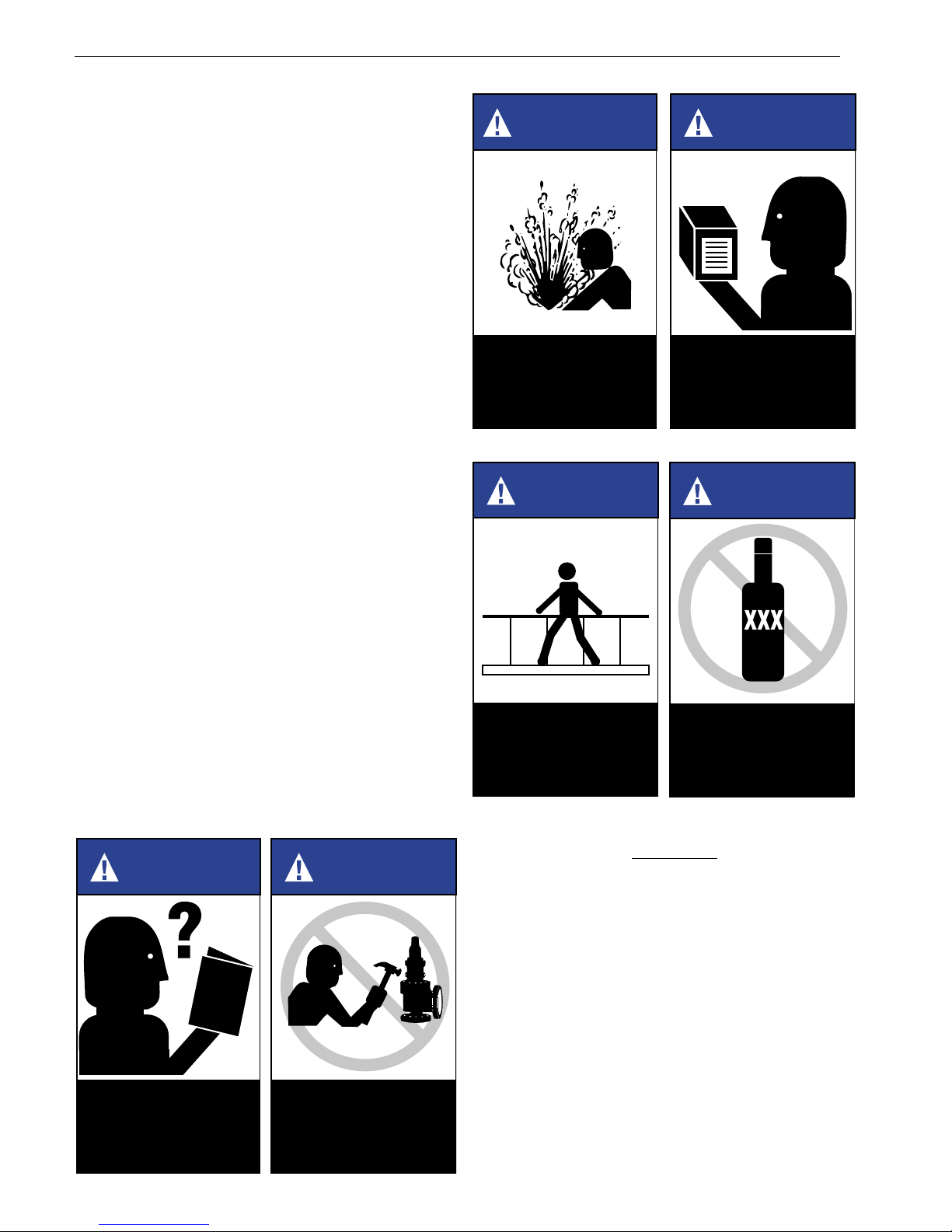
1. WARNING: Allow the system to cool to
room temperature before cleaning, servicing or
repairing the system. Hot components or fluids
can cause severe personal injury or death.
2. WARNING: Always read and comply with
safety labels on all containers. Do not remove or
deface the container labels. Improper handling or
misuse could result in severe personal injury or
death.
3. WARNING: Never use pressurized
fluids/gas/air to clean clothing or body parts. Never
use body parts to check for leaks or flow rates or
areas. Pressurized fluids/gas/air injected into or
near the body can cause severe personal injury or
death.
4. WARNING: It is the responsibility of the owner
to specify and provide guarding to protect persons
from pressurized or heated parts. Contact with
pressurized or heated parts can result in severe
personal injury or death.
5. WARNING: Do not allow anyone under
the influence of intoxicants or narcotics to work on
or around pressurized systems. Workers under
the influence of intoxicants or narcotics are a
hazard both to themselves and other employees
and can cause severe personal injury or death to
themselves or others.
6. WARNING: Incorrect service and repair
could result in product or property damage or
severe personal injury or death.
WARNING
Improper use or repair of
pressurized media or
steam device may result
in severe personal injury
or death.
WARNING
Provide and use guarding
to prevent contact with
heated and/or
pressurized parts
WARNING
Heed all container label
warnings.
WARNING
Do not work with valves
while under the
influence of intoxicants
or narcotics.
WARNING
All potential hazards may
not be covered in this
manual.
CON-2
WARNING
Improper tools or
improper use of right
tools could result in
personal injury or
product damage.
7. WARNING: These WARNINGS are as
complete as possible but not all-inclusive. Dresser
cannot know all conceivable service methods nor
evaluate all potential hazards.
8. WARNING: Use of improper tools or
improper use of right tools could result in personal
injury or product or property damage.
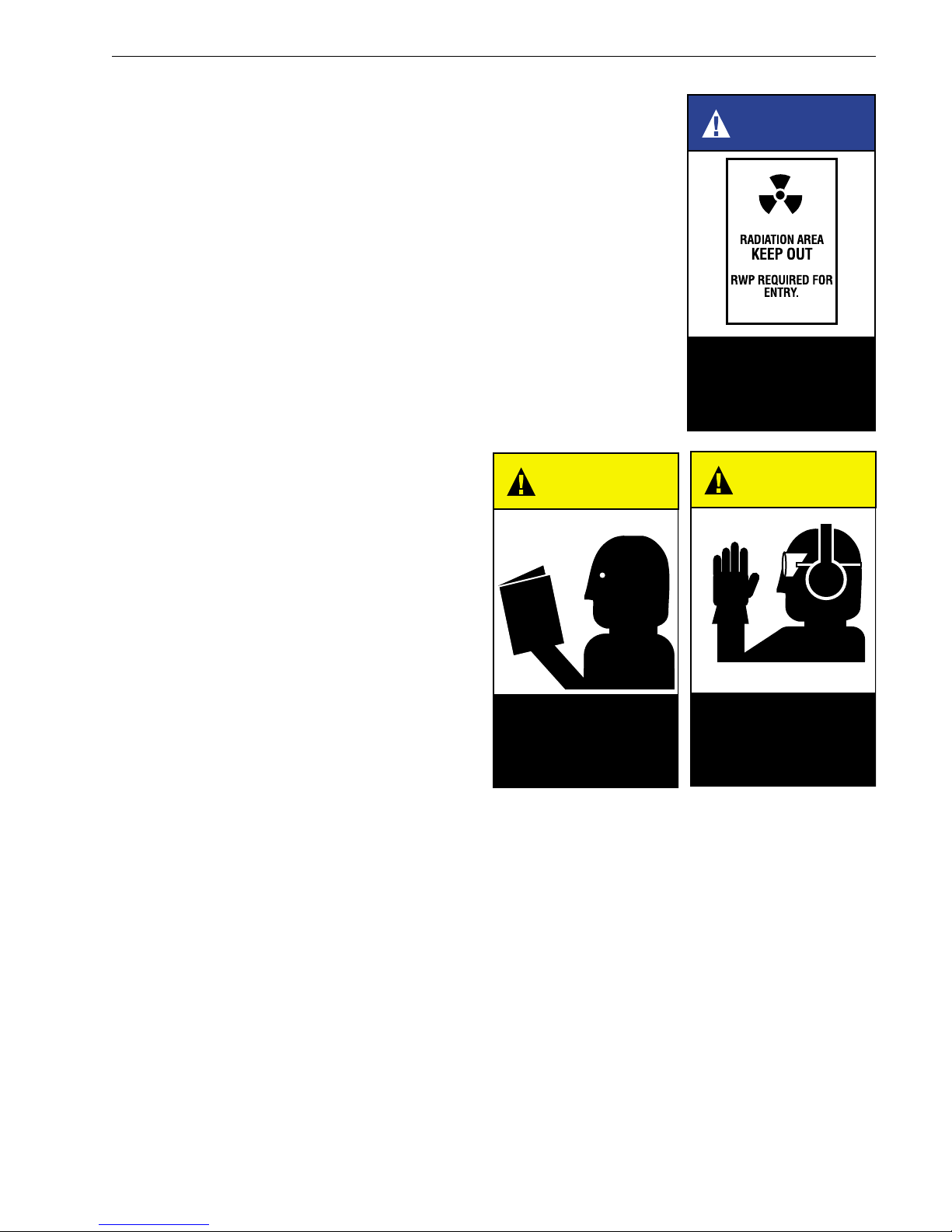
9. WARNING: Some valve products manufactured by
DVCD may be used in radioactive environments.
Consequently, prior to starting any operation in a
radioactive environment, the proper “health physics”
procedures should be followed, if applicable.
Page 3
WARNING
sonal
1. CAUTION: Heed all service manual warnings.
Read installation instructions before installing
valve(s).
2. CAUTION: Wear hearing protection when testing
or operating valves.
3. CAUTION: Wear appropriate eye and clothing
protection.
4. CAUTION: Wear protective breathing apparatus
to protect against toxic media.
NOTE:
Any service questions not covered in this manual
should be referred to Dresser’s Service Department,
Phone (318) 640-6055.
CAUTION
Heed all service manual
warnings. Read
installation instructions
before installing valve(s).
Know nuclear health
physics procedures, if
applicable, to av oid
possible severe per
injury or death.
CAUTION
Wear necessary
protective equipment
to prevent possible
injury .
▲
CON-2

Page 4
II. Terminology for Safety
Relief Valves
• Accumulation
Accumulation is the pressure increase over the
maximum allowable working pressure of the
vessel during discharge through the pressure
relief valve, expressed as a percentage of that
pressure, or actual pressure units.
• Back Pressure
Back pressure is the pressure on the discharge
side of a safety relief valve:
1. Superimposed Back Pressure
Superimposed back pressure is the pressure
in the discharge header before the safety
relief valve opens.
a) Constant - Specify single constant back
pressure (e.g., 20 psig/1.38 bar).
b) Variable - Specify variable back
pressure range using min. and max.
limits (e.g., 0 to 20 psig/1.38 bar).
2. Built-up Back Pressure
Built-up back pressure is pressure which
develops at the valve outlet as a result of
flow, after the safety relief valve has been
opened.
• Blowdown
Blowdown is the difference between set pressure
and reseating pressure of a pressure relief valve,
expressed as a percentage of the set pressure, or
actual pressure units.
• Cold Differential Set Pressure
Cold differential set pressure is the pressure at
which the valve is adjusted to open on the test
stand. This pressure includes the corrections for
back pressure and/or temperature service
conditions.
• Differential Between Operating and Set
Pressures
Valves in process service will generally give best
results if the operating pressure does not exceed
90% of the set pressure. However, on pump and
compressor discharge lines, the differential
required between the operating and set pressures
may be greater because of pressure pulsations
coming from a reciprocating piston. It is
recommended that the valve be set as high
above the operating pressure as possible.
• Lift
Lift is the actual travel of the disc away from the
closed position when a valve is relieving.
• Maximum Allowable Working Pressure
Maximum allowable working pressure is the
maximum gauge pressure permissible in a vessel
at a designated temperature. A vessel may not
be operated above this pressure, or its equivalent,
at any metal temperature other than that used in
its design. Consequently, for that metal
temperature, it is the highest pressure at which
the primary pressure safety relief valve is set to
open.
• Operating Pressure
The operating pressure is the gauge pressure to
which the vessel is normally subjected in service.
A suitable margin is provided between operating
pressure and maximum allowable working
pressure. For assured safe operation, the
operating pressure should be at least 10% under
the maximum allowable working pressure or 5 psi
(.34 bar), whichever is greater.
• Overpressure
Overpressure is a pressure increase over the set
pressure of the primary relieving device.
Overpressure is similar to accumulation when
the relieving device is set at the maximum
allowable working pressure of the vessel.
Normally, overpressure is expressed as a
percentage of set pressure.
• Rated Capacity
Rated capacity is the percentage of measured
flow at an authorized percent overpressure
permitted by the applicable code. Rated capacity
is generally expressed in pounds per hour (lb/hr)
for vapors; standard cubic feet per minute (SCFM)
or m3/min for gases; and in gallons per minute
(GPM) for liquids.
• Relief Valve
A relief valve is an automatic pressure-relieving
device, actuated by static pressure upstream
from the valve, a relief valve is used primarily for
liquid service.
• Safety Relief Valve
A safety relief valve is an automatic pressurerelieving device which may be used as either a
safety or relief valve, depending upon application.
A safety relief valve is used to protect personnel
and equipment by preventing excessive
overpressure.
CON-2

Page 5
II. (Continued)
• Safety Valve
A safety valve is an automatic pressure-relieving
device actuated by the static pressure upstream
of the valve, and characterized by rapid opening
or pop action. It is used for steam, gas or vapor
service.
• Set Pressure
Set pressure is the gauge pressure at the valve
inlet, for which the relief valve has been adjusted
to open under service conditions. In liquid service,
set pressure is determined by the inlet pressure
at which the valve starts to discharge. In gas or
vapor service, the set pressure is determined by
the inlet pressure at which the valve pops.
• Simmer
Simmer is characterized by the audible passage
of a gas or vapor across the seating surfaces just
prior to "pop". The difference between this "start
to open pressure" and the set pressure is simmer,
and is generally expressed as a percentage of set
pressure.
• Valve Trim
Valve trim includes the nozzle and disc.
III. Introduction
A safety relief valve is an automatic pressure actuated
relieving device suitable for use either as a safety valve
or relief valve, depending on application.
Safety relief valves are used on hundreds of different
applications, including liquids and hydrocarbons;
therefore, the valve is designed to meet many
requirements. The 1900 series valves included in this
manual can
requirements. It cannot be used on ASME Code
Section I steam boilers or superheaters, but may be
used on process steam.
only
be used to meet Section VIII
IV. Design Features and
Nomenclature
• Cap and Lever Interchangeability
Many times it is necessary to change the type of
cap or lever in the field after a valve has been
installed. All flanged Consolidated® Safety Relief
Valves are designed so they can be converted to
any type of lever or cap desired. It is not necessary
to remove the valve from the installation, nor will
the set pressure be affected when making such a
change.
• Design Simplicity
Consolidated Safety Relief Valves have a minimum
number of component parts. This results in a
savings by minimizing spare parts inventory and
simplifies valve maintenance.
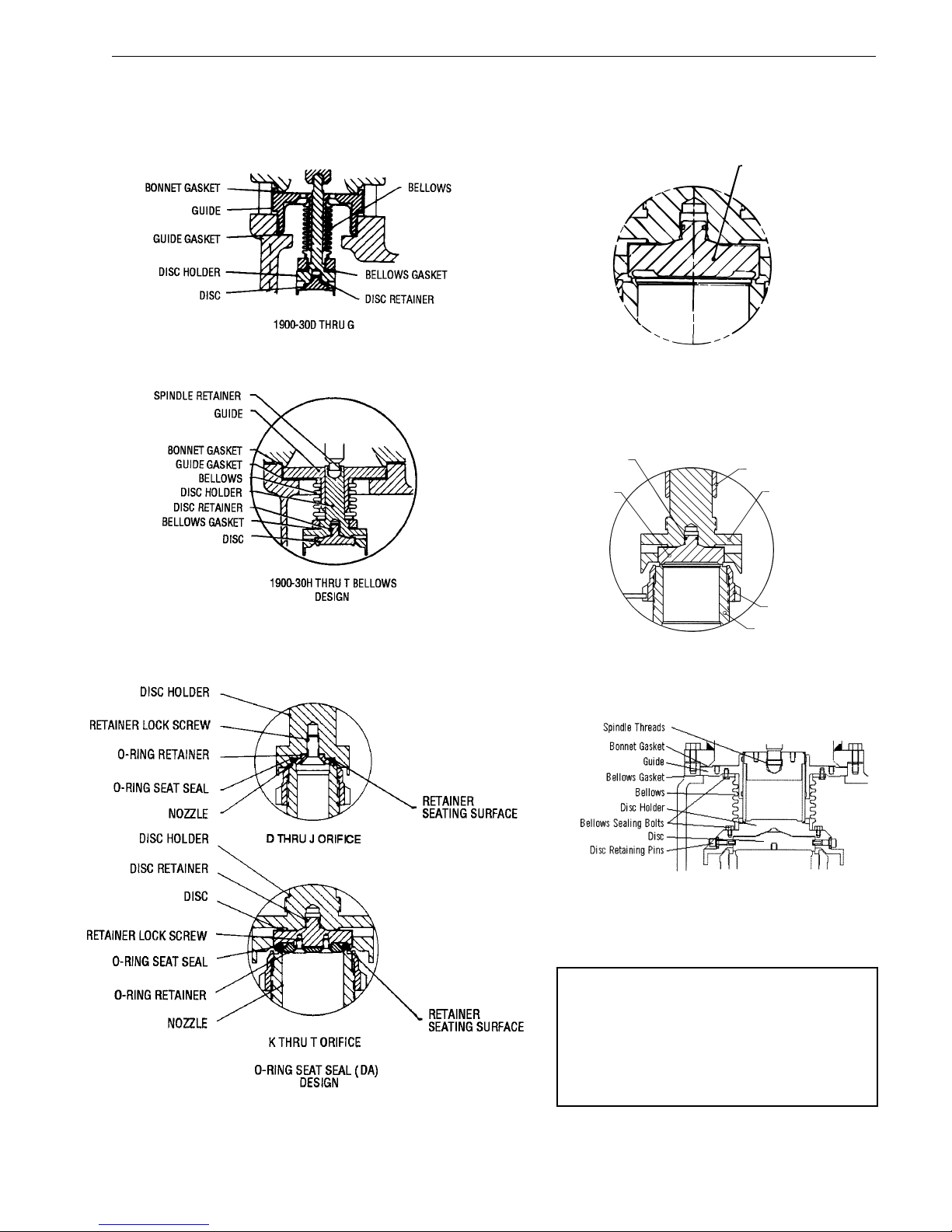
• Nomenclature Related to Design Features
Applicable nomenclature of the components of
Type 1900 valves, including those with design
options for bellows O-Ring seat, and liquid trim and
Thermodisc, is identified in Figures 1 thru 6 on
pages 6 and 7.
• Simple Blowdown Adjustment
The Consolidated single blowdown ring design
makes it possible to set and test a valve that has
been in service when it cannot be set on line and
must be taken to the customer's shop. The ring can
be positioned so that the set point can be observed
although the volume of the testing media is very
low. After the set pressure has been established,
proper blowdown can be attained by merely
positioning the ring in accordance with the adjusting
ring position shown in Tables 12-14 (as appropriate),
on page 34 of this manual.
• Valve Interchangeability
A Standard Consolidated Safety Relief Valve may
be converted to the bellows type, the O-Ring seat
seal type, etc. and vice versa. This requires a
minimum number of new parts, and results in lower
costs should conversion be required.
CON-2
Page 6
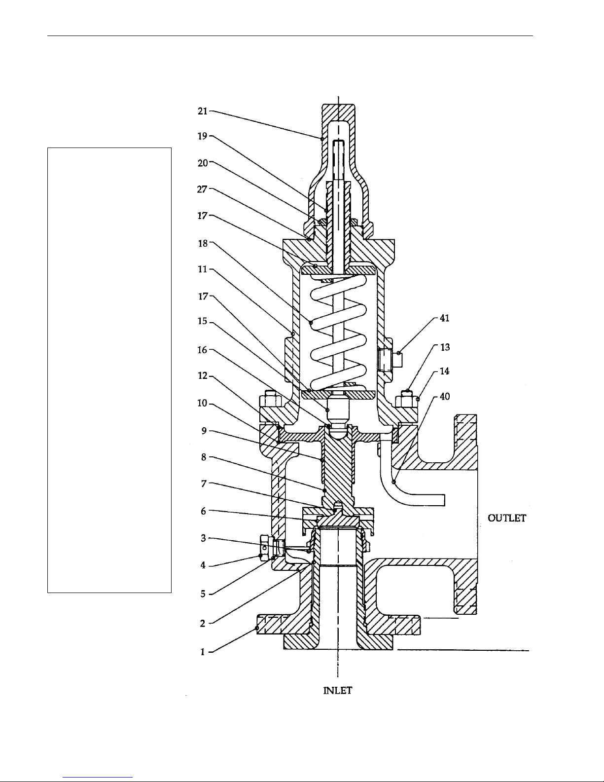
Part
No. Nomenclature
1 Base
2 Nozzle
3 Adjusting Ring
4 Adjusting Ring Pin
5 Adj. Ring Pin Gasket
6 Disc
7 Disc Retainer
8 Disc Holder
9 Guide
10 Guide Gasket
11 Bonnet
12 Bonnet Gasket
13 Base Stud
14 Stud Nut
15 Spindle
16 Spindle Retainer
17 Spring Washer
18 Spring
19 Adjusting Screw
20 Adjusting Screw Nut
21 Screwed Cap
*22 Bolted Cap
*23 Packed Cap
*24 Plain Cap
*25 Cap Bolt
*26 Cap Set Screw
27 Cap Gasket
*28 Release Nut
*29 Release Locknut
*30 Lever
*31 Lifting Fork
*32 Lever Shaft
*33 Packing
*34 Packing Nut
*35 Top Lever
*36 Drop Lever
40 Eductor Tube
41 Bonnet Vent Plug
CONSOLIDATED SAFETY RELIEF VALVE
TYPE 1900 - CONVENTIONAL
* Shown in Figures 38-42 on
page 39 of this manual.
CON-2
FIGURE 1
DESIGN OPTIONS
Page 7
THERMODISC
THERMODISC (TD)
DESIGN
FIGURE 3
FIGURE 2
DISC RETAINER
DISC
GUIDE
NOZZLE
FIGURE 5
LA Liquid Trim Design
(See Fig. 20)
FIGURE 6
V & W Orifice Only
DISC HOLDER
PART INTEGRITY
ESPECIALLY DESIGNED
FOR SHORT BLOWDOWN
AND SMOOTH CHATTERFREE OPERATION
AT MAXIMUM CAPACITY.
ADJUSTING RING
FIGURE 4
NOTE:
A combination of the O-Ring seat
seal and liquid trim design options is
designated as DA-LA.
CON-2
Page 8
V. Handling, Storage and
Pre-Installation
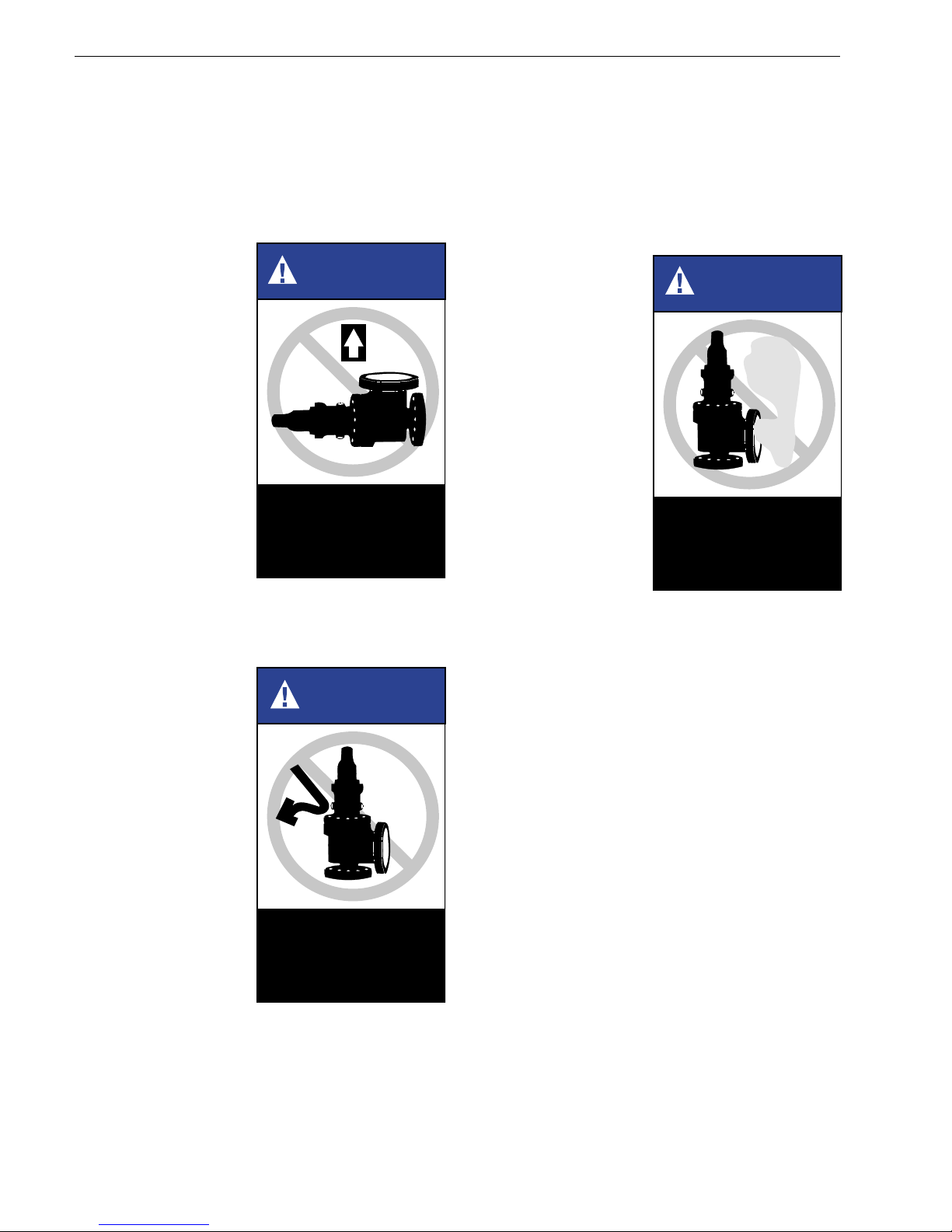
• Handling
A flanged valve, either crated or uncrated, should
always be kept with the inlet flange down (i.e., in
order to prevent possible misalignment and damage
to internals).
Uncrated valves
should be moved or
hoisted by wrapping
a chain or sling
around discharge
neck, then around
upper bonnet
structure in such
manner as will
ensure the valve is in
a vertical position
during lift, i.e. not
lifted in horizontal
position.
NOTE:
Never lift the full
weight of the valve
by the lifting lever.
Crated valves should always be lifted with the
inlet flange down, i.e., same as installation
position.
WARNING
Do not lift horizontally ,
or hook to lifting lever .
• Storage
Safety relief valves should be stored in a dry
environment to protect them from the weather.
They should not be removed from the skids or
crates until immediately prior to installation.
Flange protectors and seating plugs should not be
removed until the valve is ready to be bolted into
the installation, i.e., both inlet and outlet.
• Pre-installation
When safety relief
valves are uncrated,
and the flange
protectors or sealing
plugs removed
immediately prior to
installation,
meticulous care
should be exercised
to prevent dirt and
other foreign
materials from
entering the inlet and
outlet ports while
bolting in place.
WARNING
Prevent dirt from
entering outlet or inlet
port.
Safety relief valves,
either crated or
uncrated, should
never be subjected
to sharp impact. This
would be most likely
to occur by bumping
or dropping during
loading or unloading
from a truck. While
hoisting to the
installation, care
should be taken to
prevent bumping the
valve against steel
structures and other
objects.
WARNING
Handle carefully . Do
not drop or strike.
CON-2
Page 9
VI. Recommended Installation
Practices
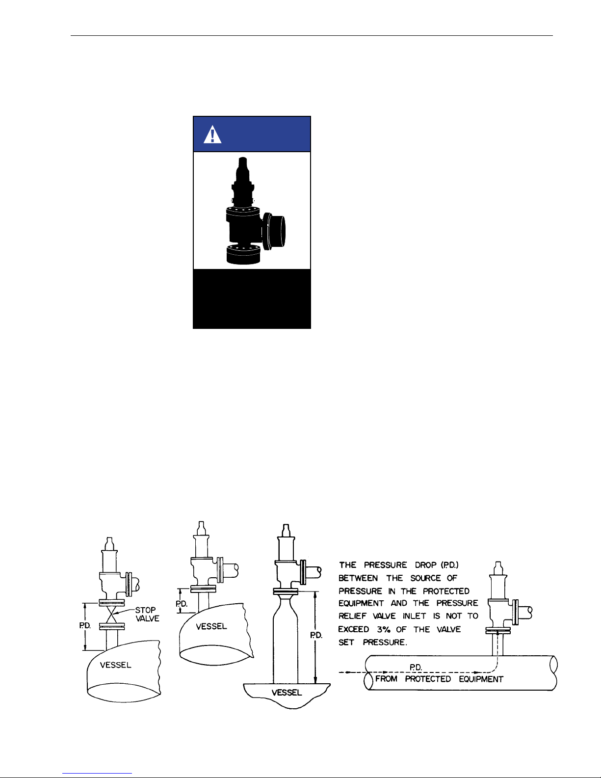
A. Mounting Position
Safety relief valves
should be mounted
in a vertical upright
position (per API
RP520). Installing
a safety relief valve
in other than a
vertical position (±1
degree) will
adversely affect its
operation in
varying degrees,
as a result of
induced
misalignment of
moving parts.
A stop valve may
be placed between
the pressure vessel
and its relief valve only as permitted by code
regulations. If a stop valve is located between
the pressure vessel and safety relief valve, the
stop valve port area should equal or exceed the
nominal internal area associated with the pipe
size of the safety relief valve inlet. The pressure
drop from the vessel to the safety relief valve
shall not exceed 3% of the valve's set pressure,
when flowing at full capacity.
WARNING
Mount safety relief
valves in only a vertical
upright position.
All flange bolts should be drawn evenly to prevent
distortion of the valve body and the inlet nozzle.
Safety relief valves should be located for easy
access and/or removal so that servicing can be
properly performed. Sufficient working space
should be provided around, and above, the valve.
B. Inlet Piping
The inlet piping (see Figure 7, below) to the valve
should be short and direct from the vessel, or
equipment, being protected. The connection to
the vessel should be provided with a radius to
permit smooth flow to the valve. Sharp corners
should be avoided. If this is not practical then the
inlet should be bored at least one additional pipe
diameter. In any event, the pressure drop from
the vessel to the valve should not exceed 3% of
valve set pressure when the valve is flowing full
capacity. In no event should the inlet piping be
smaller in diameter than the inlet connection of
the valve. Excessive pressure drop at the inlet of
a pressure relief valve in gas, vapor, or flashingliquid service will cause extremely rapid opening
and closing of the valve, which is known as
"chattering". Chattering will result in lowered
capacity and damage to the seating surfaces.
The most desirable installation is that in which
the nominal size of the inlet piping is the same as,
or greater than, the nominal size of the valve inlet
flange, and in which the length does not exceed
the face-to-face dimensions of a standard tee of
the required pressure class.
The flanges and sealing faces of the valve and all
connecting piping must be free from dirt, sediment
and scale.
FIGURE 7
CON-2
Page 10
VI.B. (Continued)
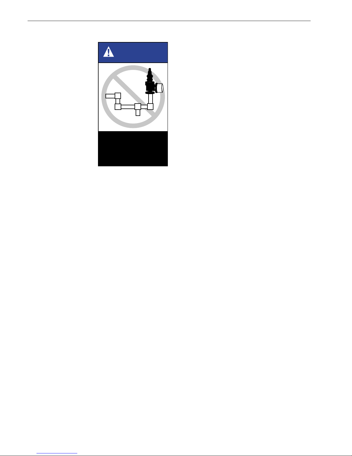
Safety relief valve
inlets should not be
located at the end
of a long, horizontal
inlet pipe through
which there is
normally no flow.
Foreign matter
may accumulate,
or liquid may be
trapped, and may
interfere with the
operation of the
valve or be the
cause of more
frequent valve
maintenance.
Safety relief valve
inlets should not be located where excessive
turbulence is present such as near elbows, tees,
bends, orifice plates, or throttling valves.
Section VIII of the ASME Boiler and Pressure
Vessel Code requires that the design of the inlet
connection consider stress conditions induced
by reaction forces during valve operation, by
external loading, by vibration and by loads due to
thermal expansion of discharge piping.
1. The determination of reaction forces during
valve discharge is the responsibility of the
vessel and/or piping designer. DVCD
publishes certain technical information
about reaction forces under various fluid
flow conditions, but assumes no liability for
the calculations and design of the inlet
piping.
WARNING
Do not locate valve at
end of pipe thru which
there is normally no
flow, or near elbo ws,
tees, bends, etc.
3. Vibrations in the inlet piping systems may
cause valve seat leakage and/or fatigue
failure of the piping. These vibrations may
cause the disc seat to slide back and forth
across the nozzle seat and result in damage
to the seating surfaces. Vibration may also
cause separation of the seating surfaces
and premature wear to certain valve parts.
High-frequency vibrations are more
detrimental to pressure relief valve tightness
than low-frequency movements. This effect
can be minimized by providing a larger
difference between the operating pressure
of the system and the set pressure of the
valve, particularly under high-frequency
conditions.
4. Temperature changes in the discharge
piping may be caused by fluid flowing from
the discharge of the valve, prolonged
exposure to the sun, or heat radiated from
nearby equipment. Any change in
temperature of the discharge piping will
cause a change in the length of the piping.
The resulting change in length may cause
stresses which will be transmitted to the
pressure relief valve and its inlet piping.
Stresses caused by thermal changes in the
discharge piping can be avoided by proper
support, anchoring, or provision for flexibility
of the discharge piping. Fixed supports
should not be used.
2. External loading by poorly designed
discharge piping and support systems can
be the cause of excessive stresses and
distortions in the valve as well as the inlet
piping. The stresses set up in the valve
may cause malfunctioning or leakage of
the valve. Forced alignment of the
discharge piping will also induce such
stresses. Discharge piping should be
independently supported and carefully
aligned.
▲
CON-2
Page 11
VI. (Continued)
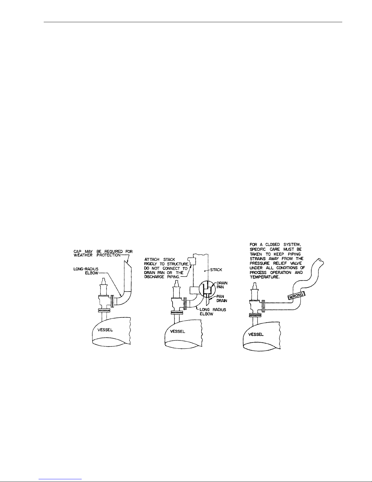
C. Outlet Piping
Alignment of the internal parts of a safety relief
valve is important to ensure proper operation
(see Figure 8, below). Although the valve body
will withstand a considerable mechanical load,
unsupported discharge piping consisting of more
than a companion flange, long radius elbow and
a short vertical pipe is not recommended. Care
should be taken to ensure thermal expansion of
piping and support system does not produce
strains in a valve. Spring supports are
recommended where this may be the case. The
discharge piping should be designed to allow for
vessel expansion as well as expansion of the
discharge pipe itself. This is particularly important
on long distance lines.
Consideration should be given to discharge pipe
movement resulting from wind loads. A continual
oscillation of the discharge piping introduces
stress distortion in the valve body and the resultant
movement of the internal parts may cause
leakage.
Where possible, drains should be piped away to
prevent the collection of water or corrosive liquid
in the valve body. Attention should be given to
the support of the drainage piping.
When two or more valves are piped to discharge
into a common header, the built-up back pressure
resulting from the opening of one (or more)
valve(s) may cause a superimposed back
pressure in the remaining valves, unless the
bonnet is vented. Under these conditions, use of
bellows valves is recommended. Bellows valves
may also permit use of a smaller size manifold.
In every case, the nominal discharge pipe size
should be as large as, or larger than, the nominal
size of the pressure relief valve outlet flange. In
the case of long discharge piping, it sometimes
must be much larger.
NOTE:
Bonnet vent is to be plugged for all nonbellows valves. Bellows valves must have
open bonnet vent.
▲
FIGURE 8
CON-2
Page 12
Valve caps and bonnets
can trap fluids. Use
caution when removing
to prevent injury or
environmental damage.
CAUTION
VII. Disassembly Instructions
NOTE:
Many pressure vessels
that are protected by
Consolidated® Safety
Relief Valves contain
dangerous materials.
Decontaminate and
clean the valve inlet and
outlet and all external
surfaces in accordance
with the cleaning and
decontaminating
recommendations in
the appropriate Material
Safety Data Sheet.
A. General
Information
Consolidated
Safety Relief
Valves can be
easily
disassembled for
inspection,
reconditioning
seats, or replacing
internal parts.
Appropriate set
pressure can be
established after
reassembly.
(Again, refer to
Figures 1-6, on
pages 6 and 7, for
parts nomenclature.)
®
Decontaminate or clean if
necessary before pretesting or
disassembly . Safety and
environmental precautions must
be taken for the decontamination
or cleaning method used.
DANGER
DANGER
Do not remove bolts if
pressure in line, as this
will result in severe
personal injury or death.
B. Specific Steps
1. Remove the
cap (including lifting
gear); then,
remove the
cap gasket, if
applicable.
2. Remove the
adjusting
ring pin and
gasket. If the
existing
blowdown is
to be
restored
upon
reassembly,
the position
of the
adjusting
ring, with respect to the disc holder, should
be determined. To do this, turn the adjusting
ring counterclockwise (i.e., move notches
on the adjusting ring from left to right).
Record the number of notches passing the
ring pin hole, which are required for the ring
to contact the disc holder. This information
will be used in setting the ring upon
reassembly of the valves.
3. a. For D-T Orifice Valves: Loosen the
adjusting screw nut. Using a Depth
Micrometer or a Dial Caliper, measure the
distance from the top of the spindle to the
top of the Adjusting Screw. This allows the
adjusting screw to be re-adjusted close to
the proper spring compression without
excessive testing. Record the
measurement for reference when reassembling the valve. Note: This
procedure does not substitute for actual
NOTES:
• Before starting to disassemble the valve, be sure
that there is no media pressure in the vessel.
• Parts from one valve should not be interchanged
with parts from another valve.
CON-2
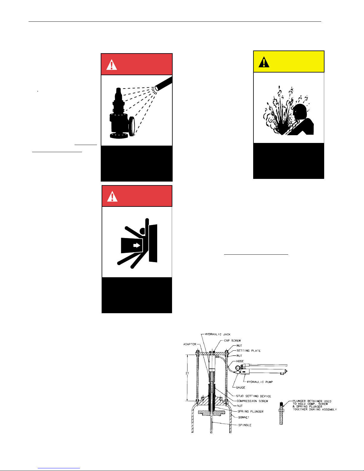
Ram In Use
FIGURE 9
Page 13
VII.B. (Continued)
pressure testing. Remove the
Compression Screw from the Bonnet. Use
pliers to prevent the Spindle from turning
when removing the Compression Screw.
b. For V and W Orifice Valves: Attach the
setting device. Apply enough pressure to
the plunger using the ram to free the
compression screw. Unscrew the
compression screw completely out of the
bonnet. The valve should be set using the
setting procedure after reassembly.
4. Remove the stud nuts and lift off the bonnet.
Next, remove the bonnet gasket.
5. Remove the spring and spring washers.
The spring and spring washers should
be kept together, as a unit, at all times.
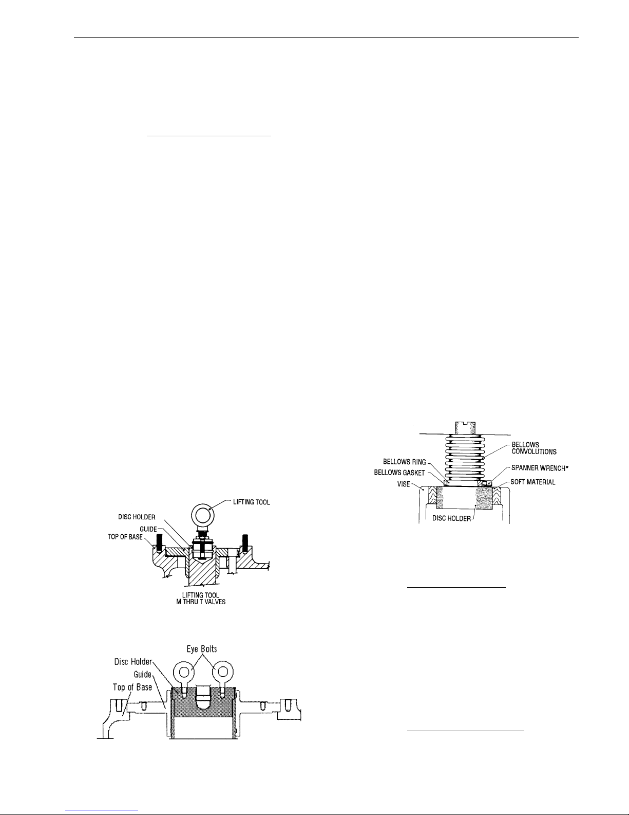
6. For D thru M orifice valves, remove the
upper internal parts by carefully pulling
“straight up” on the spindle. For bellows
valves, care should be taken to avoid
damaging the bellows or its flange. If parts
are fouled, use a suitable solvent for
loosening the components. For the P thru
T orifice valves, special lifting tools are
available for ease of upper, internal-parts
removal. First, remove the spindle by
using a screwdriver to compress the spindle
retainer. Then insert the lifting tool (see
Figure 10, below) into the disc holder spindle
pocket and tighten the eyebolt. Remove
the disc holder and disc by lifting up on the
lifting tool. For V and W orifice valves, use
the lifting lugs to lift the disc holder top and
remove all internals.
7. To remove the spindle from the disc holder
for D thru M orifice valves, clamp the skirt
portion of the disc holder snugly between
two wooden V-blocks in a suitable vise
(see Figure 11, below). Then compress
the spindle retainer with a screwdriver or
similar tool through the slots provided, and
remove the spindle.
8. Remove guide from the disc holder. (For
restricted lift valves, refer to Paragraph
X.L., on page 28 of this manual.) For V and
W orifice, unbolt bellows from guide before
guide removal.
9. For D-T orifice bellows valves, the bellows
is attached to the disc holder by right-hand
threads. Apply a special spanner wrench*
to the bellows ring, and remove by turning
counterclockwise (again, see Figure 11,
below). The bellows convolutions are very
thin, and fragile, and care should be taken
to protect them from damage at all times.
Next, remove the bellows gasket. For V
and W orifice bellows valves, the bellows is
bolted to the guide and disc holder. These
bolts should be removed before removal of
the guide.
FIGURE 10
FIGURE 10 b
* Drift Pins, See Section XVII, page 43 for details.
FIGURE 11
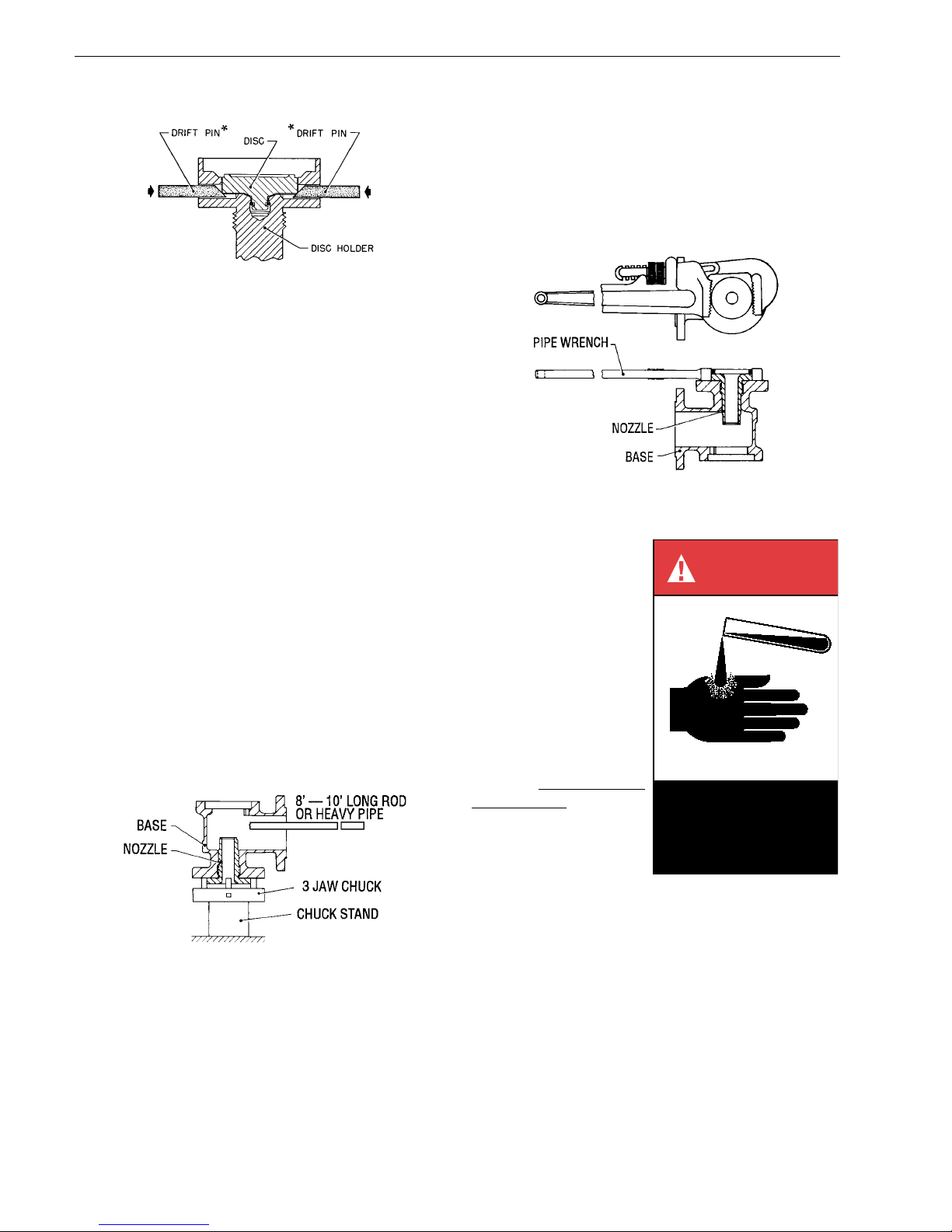
10. a. For D-T Orifice Valves: Remove the disc
from the disc holder in the following manner.
Clamp the stem portion of the disc holder,
disc end up, firmly between two wooden Vblocks in a vise. Then start special drift
pins* into the holes in the disc holder (see
Figure 12) with the tapered portion of the
pins working against the top of the disc as
indicated. Tap each pin alternately, with a
light machinist’s hammer, until the disc
snaps out of the recess in the disc holder.
b. For V and W Orifice Valves: Turn the disc
holder on its side. Remove the retaining
bolts. Attach the lifting lug to the disc and lift
out.
CON-2
Page 14
Follow recommendations for
safe handling in the solvent’s
Material Safety Data Sheet and
observe safe practices for any
cleaning method.
DANGER
VII.B. (Continued)
FIGURE 12
11. For O-Ring seat seal valves only, remove
the retainer lock screw(s), retainer and ORing.
12. Remove the adjusting ring by turning it
counterclockwise (left-handed).
13. The nozzle should be removed from the
base. (Reference nozzle removal methods
in paragraph 14.)
14. The nozzle is normally removed for routine
maintenance and service. The nozzle is
assembled to the base with threads and
may be removed by turning it
counterclockwise. To facilitate removal of
the nozzle from the base, it may be found
beneficial to first soak the threaded joint
with a suitable penetrating liquid or solvent.
In instances where the nozzle is frozen into
the base, its removal may be helped by
sufficiently heating the base from the outside
with a blowtorch in the area of the nozzle
threads, while dry ice or other cooling
medium is applied to the inside of the
nozzle.
NOTE:
Exercise care when inserting a rod or
pipe in the outlet, in order to ensure that
the valve nozzle is not damaged during
this operation.
16. Use a large pipe wrench on nozzle flange
to remove the nozzle from the base (see
Figure 14).
FIGURE 14
VIII. Cleaning
1900 Series Safety Relief
Valve internal parts may
be cleaned with industrial
solvents, cleaning
solutions and wire
brushes. If you are using
cleaning solvents, take
precautions to protect
yourself from potential
danger from breathing
fumes, chemical burns, or
explosion. See the
solvent’s Material Safety
Data Sheet for safe
handling recommendations and equipment.
FIGURE 13
NOTE:
Should heat be applied, use care to
prevent cracking of cast parts.
15. Utilize a 3 or 4 jaw chuck welded vertically
to a stand bolted to a concrete floor. Chuck
on nozzle flange and break the body loose
CON-2
from the nozzle with a heavy rod or pipe
(see Figure 13).
It is not recommended to
“sand blast” internal parts as it can reduce the dimensions
of the parts. The base, bonnet and cap castings may be
sand blasted with care not to erode internal surfaces, or
damage machined surfaces.
IX. Parts Inspection
A. Nozzle Inspection
Criteria
Nozzle should be replaced if:
1. Dim. from seat to first thread after
remachining and lapping is less than D min. on Table 1.
2. Both thread sections are damaged from
pitting and/or corrosion.
 Loading...