

DResearch TeleObserver MR3140 User Manual
video
solutions
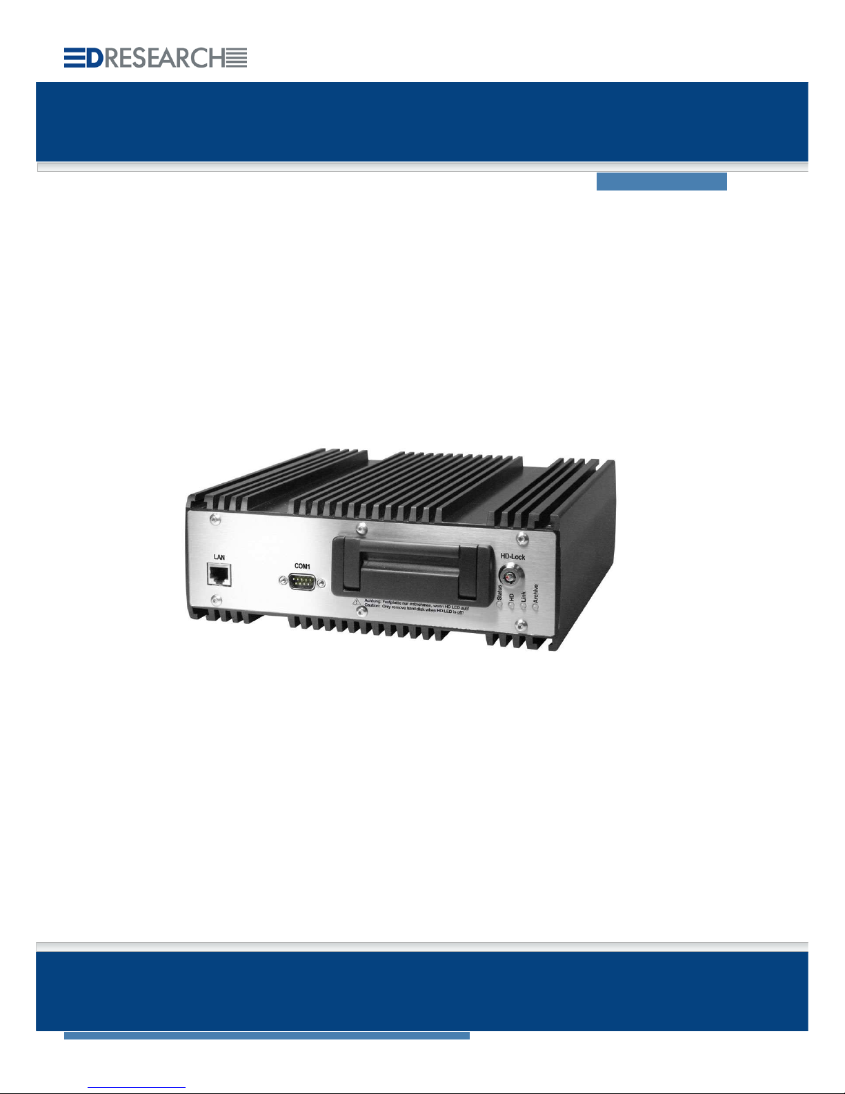
TeleObserver MR3140
Mobile hybrid digital video recorder
User manual
Firmware 6.1

DResearch – User Manual TeleObserver MR3140 2011-02-03
2
This document may not be copied, reproduced, summarised, translated or otherwise reproduced
without the express permission of DResearch. It has been compiled to the best knowledge of
DResearch. DResearch is not responsible for the consequences of typographical or residual errors
relating to the user manual which is only informative in nature.
DResearch retains the right to make amendments to the contents of the user manual without having
any duty to inform third parties. Any change made to the product or its associated software not
expressly confirmed by DResearch will result in the termination of the operating licence and warranty.
Any company and/or product names are trade names and or legally protected trademarks of the
relevant manufacturer.
© Copyright 2011 DResearch Fahrzeugelektronik GmbH. All rights reserved.

DResearch – User Manual TeleObserver MR3140 2011-02-03
3
C O NT E NT S
1 General information about DResearch video systems............................................................. 5
1.1
System overview and new functions in this version...............................................................6
1.2
Scope of delivery.................................................................................................................... 7
1.3
Accessories & additional devices...........................................................................................7
1.4
Safety advice.......................................................................................................................... 8
1.5
Warranty................................................................................................................................. 9
1.6
Certifications, standards and conformities............................................................................. 9
1.7
Scope of use ........................................................................................................................10
1.8
General installation information............................................................................................ 10
1.9
Temperature range ..............................................................................................................11
1.10 System components and device features............................................................................ 12
2 The recording device MR3140 in detail ....................................................................................15
2.1
Device description................................................................................................................15
2.2
Changing and inserting the removable disk.........................................................................16
2.3
Significance of the status LEDs ...........................................................................................17
2.4
Device interfaces.................................................................................................................. 18
2.4.1 Analogue video inputs 1 ... 4 – connection of analogue CCTV cameras........................18
2.4.2 LAN Interface – connection of IP network cameras or other devices.............................. 18
2.4.3 Video Out 1 and 2 – connection of control monitors ....................................................... 19
2.4.3.1 Sequential video output and multiviews.................................................................. 19
2.4.3.2 Display of information and system events (OSD)...................................................20
2.4.4 Power supply for the device and cameras....................................................................... 21
2.4.5 COM 1 – Serial data transmission and GPS connection.................................................22
2.4.6 COM 2 Interface – External modem connection............................................................. 22
2.4.7 COM 3 and COM 4–Interface (IBIS and RS485)............................................................. 22
2.4.8 The audio interface..........................................................................................................23
2.4.9 GPIO-interface – detector inputs and switch relay outputs .............................................23
2.4.10 GPIO-Interface ............................................................................................................ 24
2.4.11 “Ext. Devices“ Interface – IBIS, CAN and RS485 .......................................................25
3 Device Configuration - The main program CMS and its menu .............................................. 26
3.1
SystemManagement –module for device configuration....................................................... 27
3.1.1 The device configuration..................................................................................................29
3.1.1.1 System :: Basic settings..........................................................................................31
3.1.1.2 System :: Time ....................................................................................................... 34
3.1.1.3 System :: Passwords............................................................................................... 35
3.1.1.4 System :: Version....................................................................................................36
3.1.1.5 Devices :: Cameras.................................................................................................36
3.1.1.6 Devices :: IP-Cameras ............................................................................................ 39
3.1.1.7 Devices :: Detectors................................................................................................41
3.1.1.8 Devices :: Relays ....................................................................................................42
3.1.1.9 Devices :: Audio ...................................................................................................... 42
3.1.1.10
Connectors :: GPS..............................................................................................43
3.1.1.11
Connectors :: Network ........................................................................................ 44
3.1.1.12
Video output :: MultiView .................................................................................... 45
3.1.1.13
Video output :: Transfer order............................................................................. 45
3.1.1.14
Activations...........................................................................................................46
3.1.1.15
System events ....................................................................................................48
3.2
The web interface of the system .......................................................................................... 51

DResearch – User Manual TeleObserver MR3140 2011-02-03
4
4 Relevant comments on the daily operation ............................................................................. 52
4.1
Power supply and shutdown of the systems.................................................................. 52
4.2
Hold-back time of the permanent recordings versus data privacy .............................. 52
4.3
Shutdown behaviour of the system .................................................................................53
4.3.1 Shutdown behaviour during permanent and alarm recordings........................................53
4.3.2 Shutdown behaviour during data research......................................................................54
4.3.3 Influencing of the recording during data research........................................................... 54
4.4
Overheat protection: temperature shutdown level of the system......................................... 55
4.5
Default configuration for factory reset .................................................................................. 55
5 Update & Reset, maintenance, problem analysis and technical support............................. 56
5.1
Update of the device via the update tool..............................................................................56
5.2
Update and Reset of the device via the web interface ........................................................56
5.3
Maintenance, cleaning and care of the system....................................................................57
5.4
Problem analysis and resolution .......................................................................................... 58
5.5
Technical support by the manufacturer................................................................................59
6 Technical data of the MR3140 ...................................................................................................60
7 Technical drawing ......................................................................................................................62
8 Abbreviations.............................................................................................................................. 63

DResearch – User Manual TeleObserver MR3140 2011-02-03
5
1 General information about DResearch video systems
Congratulations on the acquisition of your MR3140!
Dear customer, thank you for deciding to purchase an MR3140 mobile hybrid recorder, we are most
grateful for your custom. You have made an excellent choice in acquiring this device, a top quality
product from DResearch. The MR3140 is a compact digital unit for recording video sequences from
analogue and digital cameras as well as other associated data (IBIS and GPS). With industrial styling
and a robust nature, the device is intended for mobile and static use under the severest conditions.
Because of the particular application requirements of mobile CCTV monitoring, the MR3140 is
designed to be a compact, efficient system with a long service life.
Owing to its tolerance of temperature variations and its resistance to vibration and shocks, corrosion,
dust and moisture, the unit is particularly well equipped for flexible use in vehicles. The system
digitizes and records up to 4 analogue video streams. Alternatively up to 8 digital video streams from
IP cameras can be recorded from a local network. The MR3140 also has many interfaces for
configuration, expansion, maintenance and integration in all-in-one systems. As many as 12 IP
cameras can be set up in the network for display on a control room monitor.
Please take some time to read the user manual carefully so that you are familiar with the complete
functional scope of the system and its application requirements. The documentation for the device is
provided on the software CD supplied with the device.
We wish you every success in working with the MR3140 mobile hybrid recorder!
DResearch devices at a glance
MR3060* MR3140 MR3180 TO1200* TO3100
Analogue recording yes yes yes - yes
Digital recording - yes yes - Video-IN analogue (max.) 6 4 8 4 8
Video-IN digital (max.) - 8 8 - Video-OUT 1 2 2 - 1
Transmission via SMS, Video (GSM,
GPRS, EDGE) if an alarm is triggered
yes *** yes *** yes *** yes ** yes **
GPS data recording yes yes yes yes yes **
IBIS data recording yes yes yes - yes **
Max. capacity HD in GB 500 250 250 - 160
Motion detection yes yes yes - Sabotage detection yes yes yes - Encryption/digital signature yes yes yes yes yes
Digital inputs 6 6 8 6 8
Digital outputs/switch relays 4 4 2 4 6
RS232/485 yes yes yes yes yes
Video management software incl. yes yes yes yes yes
* The device TO1200 is from 2010 no longer available, the device MR3060 is available from 2010.
** optional, depends on type of device
*** only for SMS transmission via external device

DResearch – User Manual TeleObserver MR3140 2011-02-03
6
1.1 System overview and new functions in this version
System overview
Recording of video, audio, IBIS, GPS
Hybrid mode: recording of up to 8 analogue and digital camera signals
Formats - analogue: H264, CIF + 2CIF; digital: MJPEG, up to 1 MPx
Hard disks: HDD / SSD (S-ATA) with capacity between 80 and 250 GB
Recording into separated archives (alarm, pre-alarm, ring)
Automatic deleting of archives, configurable hold-back time and maximum recording time
Operating modes: pause, continuous recording, sleep
Selftest of the unit and automatic securing of the data integrity
Digital inputs for switches / buttons and alarm detectors
Digital relay outputs to switch external devices
Robust and fanless design, maintenance free, vandal safe
Vehicle fit and certified in accordance to e1 and EN50155
Extensive configuration options
Ethernet interfaces, serial interface RS232, 485
Sending SMS in the case of an alarm and for defined system events
Data security: multi-level access protection, digital signing of the recorded data
Numerous detectors for system disorders, motion and sabotage detection for analogue cameras
Logically combinable system detectors and allocation of defined actions
And much more…
A detailed overview of the possibilities of the system is given in this document and further
information materials, like system description or application concepts from DResearch –
request them or visit us on our website:
www.DResearch.de
New features in this firmware – version 6.1
Suspension of the overheating protection: The upper temperature shutdown level can be
increased – during the update – with the update tool from +55°C to +70°C. Please note the
instruction of the update tool and the corresponding annotations in this document.
Definable default configuration: During the update with the update tool you can specify if the
factory settings of the manufacturer or the current configuration of the system shall be defined as
default configuration. This default configuration will be loaded by a factory reset. Please note the
instruction of the update tool and the corresponding annotations in this document.
DResearch – User Manual TeleObserver MR3140 2011-02-03
7
1.2 Scope of delivery
Digital hybrid recorder
Removable hard disk (capacity between 80 – 250 GB)
Software for configuration and analysis (Central Monitoring Software - CMS)
Licences for the CMS
Product CD with software and documentation
1.3 Accessories & additional devices
The devices can be expanded with various accessories. For a detailed list of all the accessories
offered by DResearch, please refer to the current product catalogue. For other information and
ordering of accessories please contact your system integrator or our team direct.
Assortment of additional devices for the system:
Power supply unit 24V/2,5A
Power – plug (ready-made 75cm cable with pin sleeves)
Miscellaneous mounting material
Service cable (crosslink and patch cables, serial service cable)
Plug set GPIO, plug set Ext. Device
Power-over-Ethernet switch (PoE) for supplying power to IP cameras
DC/DC transformer (various input voltages, Out: 12-24V)
Hard disks HDD/SSD: 80 - 250 GB
Video- and network cables (CAT 5; 6 ) in various lengths
GPIO tester
Assortment of additional devices to extend the system:
WLAN modules
GPS receiver, GSM antenna in various versions
UMTS/GPRS/HSDPA/HSUPA modems for data transfer
Coupling systems for bridging vehicle clutches
Various analogue and IP network cameras
Coloured and b&w surveillance monitors for fitting into vehicles (trucks, buses,
trams, trains)
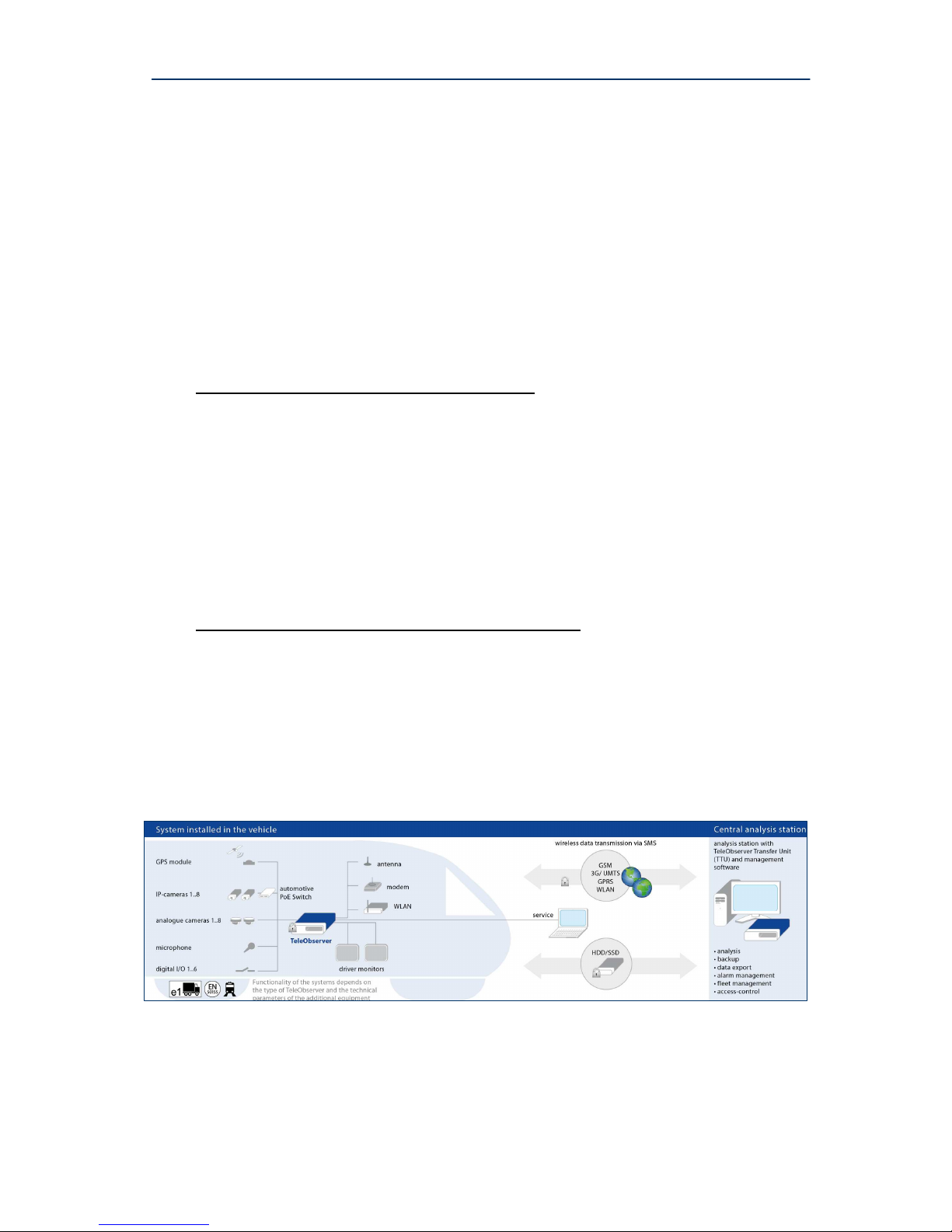
A complete installation in a rail carriage when expanded with accessories could look like this:*
* This is an illustrative example of the MR3180 – the MR3140 works with a maximum of four analogue cameras.
DResearch – User Manual TeleObserver MR3140 2011-02-03
8
1.4 Safety advice
Incorrect handling can, at its worst, lead to personal injury or destruction of the device, and/or the
termination of the guarantee. Therefore please be sure to note and follow the advice below before
operating the device.
Never try to insert objects into any device openings since this could cause short-circuits or
deliver electric shocks because of the voltage inside the unit.
Only use original parts or products recommended by the manufacturer in the operation of
the equipment. If you have a problem please consult your system integrator.
Avoid installing equipment where it could be exposed to excessive smoke, dust, vibration,
chemicals, moisture, heat, direct sunlight or electromagnetic fields. Such exposure can have
a detrimental effect on the operation of the device and – in the worst case – can cause
damage to the device.
Never operate the device in locations where there is a danger that water might penetrate the
device.
When connecting up the device with the peripherals ensure that the cable is not under
tension. Ensure all cables are installed properly.
Only remove the hard disk from the device when all the LEDs on the front panel are off. To
remind you this warning is printed on the front of the removable hard disk.
This is an (EMC, EN 55022) Class B system and can be used in all environments.
Remove only, when all LEDs are off!

DResearch – User Manual TeleObserver MR3140 2011-02-03
9
1.5 Warranty
The warranty terms for materials and manufacturing faults are, unless otherwise agreed by special
negotiation, set out by DResearch Fahrzeugelektronik GmbH in its General Terms and Conditions.
The General Terms and Conditions are to be found in the documents supplied. No further, expressed
or tacit guarantees are accepted. The manufacturer is not responsible for claims arising from the
improper handling or faulty installation by third parties.
The warranty is terminated if repairs or interventions are made by people who have not been
authorised by the manufacturer. Claims arising from the inappropriate use of the equipment, incorrect
maintenance or the use of accessories not recommended by the manufacturer are not covered under
the terms of the warranty.
Opening the device inevitably leads to the cancellation of all existing guarantee cover, guaranteed
rights and agreed warranties.
The supplied software and installation pack presuppose a conflict-free operating system. Solving
problems relating to this require detailed knowledge of the systems used or their complete
reinstallation. The manufacturer makes no guarantees that programs or systems operated by the user
will deliver the desired benefits.
If a product is returned under the terms of the warranty this is always to be agreed in advance with the
supplier, otherwise the return will not be processed. If returning an item, you will be given a returns
number which is to be used throughout the procedure. The manufacturer takes no responsibility for
damage or insurance during transit. Cash on delivery and ‘carriage forward’ shipments are not
accepted.
1.6 Certifications, standards and conformities
The device is made to current safety and reliability standards (state: 09/2008) for use in a variety of
environments. It was designed specially for use in trucks and locomotives and meets current
requirements of various European standards.
Certifications, standards and conformities:
CE compliant to EN 55022 class B
RoHS conformity
Conformity to European rail standard EN 50155
e1 certification from the German Federal Bureau of Motor Vehicles and Drivers (KBA)
Conformity to European EMC guidelines
Vibration IEC 61373 (9) and shock IEC 61373 (10.5)
Heat & fire resistance DIN 53438-2, DIN 5510-2
EN 55024, EN 60950, EN 61000, EN 50121

DResearch – User Manual TeleObserver MR3140 2011-02-03
10
1.7 Scope of use
Public transport sectors
Trams, suburban railways, underground railways, buses, local and long distance trains and other vehicles
Distribution, logistics and transport sectors
Secure cash transport, transportation of hazardous loads, trailers and storage areas, high-bay warehousing and
distribution centres, etc.
Housing and construction industry
Local properties, lifts and entrance halls as well as building sites.
Industry and commerce
Builders yards, industrial sites, waterworks and water treatment works, pumping stations, power stations,
transformer substations, wind farms, geothermal power stations, retail branches, shopping centres, etc.
Maritime - Offshore
Locks, sea level measuring stations, oil drilling platforms, off-shore wind farms, etc.
Private sector
Holiday cottages, residential property, bungalows, boats, yachts, other vessels.
Caravans, camper vans, etc.
1.8 General installation information
Power supply
The device must be plugged into a buffered power supply (UPS or unswitched supply/permanent
positive).
Do NOT use the on board train power supply switch to turn the system on. Use the ignition.
Ensure that the device is wired up exactly as described in the manual.
Ensure there is a constant power supply of 12-24 VDC. Temporary power outages will be tolerated
by the device but they are always to be avoided and can lead to system failures and permanent
damage to the equipment (e.g. from lack of proper vehicle battery maintenance).
The UPS must be a device which has been recommended by the manufacturer and has valid
certification for the application type.
Any damage resulting from disregarding this advice will not be covered by any guarantee or
warranty.
Cable length between device and cameras
Long connection paths between device and cameras have detrimental effects on the quality of the
video signals. Select camera positions so that as much as possible of the area to be monitored can be
covered with minimum cable lengths. Your system integrator will help you with the design of the
system.

DResearch – User Manual TeleObserver MR3140 2011-02-03
11
Ventilation and cooling
Avoid installations where heat can build up. The equipment is designed to function without the need
for a fault-prone fan, but adequate air circulation needs to be provided round the cooling fins.
The system is equipped with an automatic overheating protection. In this case the system will be
shut down automatically and controlled if the internal temperature is 55°C. Please note that the
internal temperature may be up to 15°C above the am bient temperature.
Select the installation place so that heat accumulations can be avoided and the system is
sufficiently cooled by air circulation. Further information about overheating protection you will find
at the end of this document.
Mounting
The device has 2 guide rails on the top and bottom which take mounting screws. If at all possible,
mount the device on a mounting plate which can also take the necessary additional components such
as a transformer and connection block.
The device must not be mounted with the hard disk drive aperture facing down! When fitting
ensure that it is possible to change the removable hard disks easily!
1.9 Temperature range
Storage temp.: maximum + 70°C
Operating temp.: 0°C to + 55°C (normal HDD)
0°C to + 70°C (HT- HDD, SSD)
Humidity: 10 … 90 % (not condensed)
When using conventional data storage devices (HDD) the unit will automatically shut down when it
reaches its temperature limit of + 55°C (for normal HDD) in order to protect the hard disk.
When the temperature reduces to below this limit, the device will automatically switch back on.
This temperature-dependent switching event is stored in a log file.

DResearch – User Manual TeleObserver MR3140 2011-02-03
12
1.10 System components and device features
The complete system consists of three different modules which communicate with each other via a
proprietary software data protocol which is the same irrespective of the operating system.
The device MR3140
Data recording and storage of video streams with metadata according to the
predetermined configuration
Storage on a removable hard disk
Connection of up to two control monitors
Function and configuration: see following chapters
Default IP address of the device when shipped: 192.168.0.1
Service computer and analysis station
Usually the review station is used for analysing the recorded data. A service laptop is often employed for
installation, configuration and system maintenance. A standard commercial computer can be used.
Currently DResearch offers two software packages:
Central Management Software (CMS)
with the modules Vision, ImageFinder and SystemManagement for
Visualisation of recorded data (video, add. data)
Searching recorded data according to freely configurable parameters (e.g. time, events etc.)
Display of live video sequences (incl. additional data)
Device configuration
Operating systems (OS) supported: Windows XP Prof. and Vista
ImageFinderNX
The analysis software ImageFinder NX is the successor of the CMS module ImageFinder
and provides a convenient search and analysis of the recorded data. The software is
usable in conjunction with the USB-TTU. A direct search at the device is possible from
version 1.5. The usage requires Windows operating systems Windows XP Prof. (SP 2)
or Vista.
The previous CMS module ImageFinder will be developed only until the end of 2009 and
then discontinued!
The TeleObserver Transfer Unit (USB-TTU)
This separate device (USB-TTU) has the following uses:
Taking the removable hard disk for the evaluation/analysis of data.
Formatting the hard disk.
Activating removable hard disks and decoding data (when using DR.Secure
encryption).
Displaying synchronous video images.
Analysing of the recorded data (video, audio, add. Data, such as IBIS and GPS).
Creating backups.
Export of video data, printing of pictures etc.
(For a detailed description of all the features have a look in the manual of the USB-TTU.)

DResearch – User Manual TeleObserver MR3140 2011-02-03
13
Detailed information you will find in this manual and the data sheet.
System specification – an overview
Hybrid recorder for recording video, audio and metadata, designed for buses, trains, trams and other
vehicles, certified to e1 and EN 50155
4 x video-in analogue (BNC), 8 x video-in to record from IP network cameras (AXIS, Mobotix and others
up to 1 Megapixel, 1280 x 1024 Pixel)
2 channel audio recording (e.g. for the documentation of the driver communication)
Removable hard disk HDD / SSD: up to 250 GB HDD
2 x video-OUT for analogue and up to 12 IP network cameras, split screen display and
onward signal switching
Recording of metadata such as IBIS (VDV 300), GPS
Interfaces: RS232, RS485, Ethernet, IBIS
6 digital alarm inputs (for alarm triggering devices) and 4 digital outputs (for switch relays)
Integrated power supply for 4 analogue cameras
Compact, robust industrial design for use in the most difficult conditions with protection against vibration
Safe from vandalism through stable cast aluminium housing (continuous casting)
Maintenance-free through fan-free operation
Software and data management
Live video pictures, search and playback function and fast video download via an Ethernet-interface
Configuration and management software with ergonomic graphical user interface
Expanded event and information management, including IBIS / GPS metadata
Support for alarm and fleet management
Data encryption, watermark, sabotage recognition, role-based access management, motion detection
Flash based real-time operating system and hardware control system
MJPEG and H.264+ (MPEG-4 AVC) picture compression with recording rates up to 200 frames per
second
SMS support for alarm events as well as for maintenance/service-support (GSM modem required)

DResearch – User Manual TeleObserver MR3140 2011-02-03
14
Feature Description
Configurable video
recording
Recording of video sequences from up to 8 cameras (hybrid operation of
analogue and IP cameras) in automatic generated archives (one ring, alarm
and pre-alarm archive per camera).
Maximum of 25 pictures/s for analogue cameras to the 4 video inputs
Recording of up to 8 IP cameras with a maximum of 25 pictures/s per camera
Definable setting for maximum age for the video footage.
Configurable picture
resolution (picture
format)
The picture format has to be determined before recording begins!
Recording formats from analogue cameras:
CIF (352 x 288 = 101 376 Pixels)
Half frame/2CIF (704 x 288 = 202 752 Pixels)
Recording formats from IP cameras:
The IP camera picture format has to be determined in the camera set up – not
via CMS!
Configurable picture
quality
For each analogue camera there are 5 different settings for the picture quality of
the recorded video footage.
The picture quality from the IP cameras is determined by the camera
configuration settings.
Configurable alarm
recording
Pre- and post-alarm recording times are configurable.
Events can be used to start alarm recording.
Data recorded with this feature are marked as such. The alarm footage is not
automatically overwritten.
The maximum age of the alarm sequences can be determined.
Activated alarm
recording display
If alarm recording is activated, this is indicated by the yellow HD LED and it is
displayed on the control monitor.
Configurable metadata
recording
Besides video footage, additional data such as date/time, camera name, IBIS
and GPS data can be recorded.
Calling up status
information
Information about the current status of the device is indicated via the devices
LEDs and displayed on a control monitor (OSD).
Display of the event
log
Information about the device is recorded in the event log. The log can be
viewed in the searching software.
System events Indicate the various device and archive conditions. They can be viewed on a
control monitor (OSD).
Motion detection Trigger-level-controlled motion detection
Motion detection can be limited by masking off particular areas of the picture.
Configurable actions in response to motion detection e.g. alarm recording
and/or switching relays.
Camera sabotage Trigger-level-controlled camera sabotage detection (only for analogue cameras)
Configurable actions in response to camera sabotage, e.g. relay switching,
sending SMS.
DResearch – User Manual TeleObserver MR3140 2011-02-03
15
2 The recording device MR3140 in detail
2.1 Device description
The MR3140 is one part of the complete recording system and works without a fan. The housing is
made from non-rusting, maintenance-free material. The data transmission and recording processes in
the device are encrypted to prevent unauthorised access to the data. The file and security operating
systems used prevent loss of important files if there is a power outage and therefore maintain
continuity.
The device forms the switching centre and link between all other system components. It provides the
interfaces for the connection of cameras, peripherals such as WLAN modem, GSM modem, PoE
switch, driver monitors, relays and switches as well as other components.
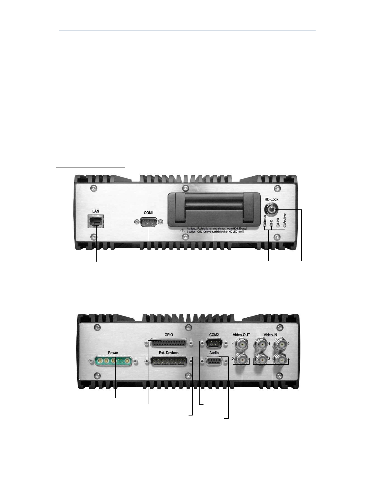
Front view of the MR3140
Rear view of the MR3140
Ethernet
removable storage disk
state - LEDs
COM1
RS 232
HD-lock
video-IN
1 .. 4
(analogue)
digital I/O power supply
audio
COM2
RS 232
video-OUT
1, 2
(analogue)
RS 485, IBIS, CAN
(optional)
DResearch – User Manual TeleObserver MR3140 2011-02-03
16
2.2 Changing and inserting the removable disk
In MR3140 devices use only the hard disks provided and pre-formated by DResearch. Only hard
disks with the same capacity should be used within each fleet. For more information and for
ordering hard disks please contact the sales team (E-Mail: sales@dresearch.de).
Use only original hard disks from the manufacturer!
Otherwise all existing warranties and guarantees are invalidated.
To prevent any manipulation of the data, the hard disk is adopted by the device. This process happens
when the device starts up with the hard disk for the first time. Only after this can recording start. To
prepare the device for recording for the first time proceed as follows:
Switch the device off and wait until all the LEDs have gone out
(by unlocking the HD lock) – this takes several seconds.
Without using physical force carefully insert a formatted (!) removable hard disk (label upwards)
in the carrier guides.
Lock the HD lock again.
The system will start again (so long as the power is on).
The hard disk capacity will be automatically allocated to the camera archives by the software.
No further intervention is necessary.
If you anticipate exchanging hard disks between different devices (so-called interchange of hard
disks) then the following details are important – please note the configuration of the basic
settings!
The hard disk is a sensitive part of the system. To ensure constantly reliable functioning we
recommend checking up the hard disks every 3 months.
After changing the hard disk the device needs 2 minutes to examine and adapt the disk. Turn off
the device after initial boot with a new disk earliest after 2 minutes!
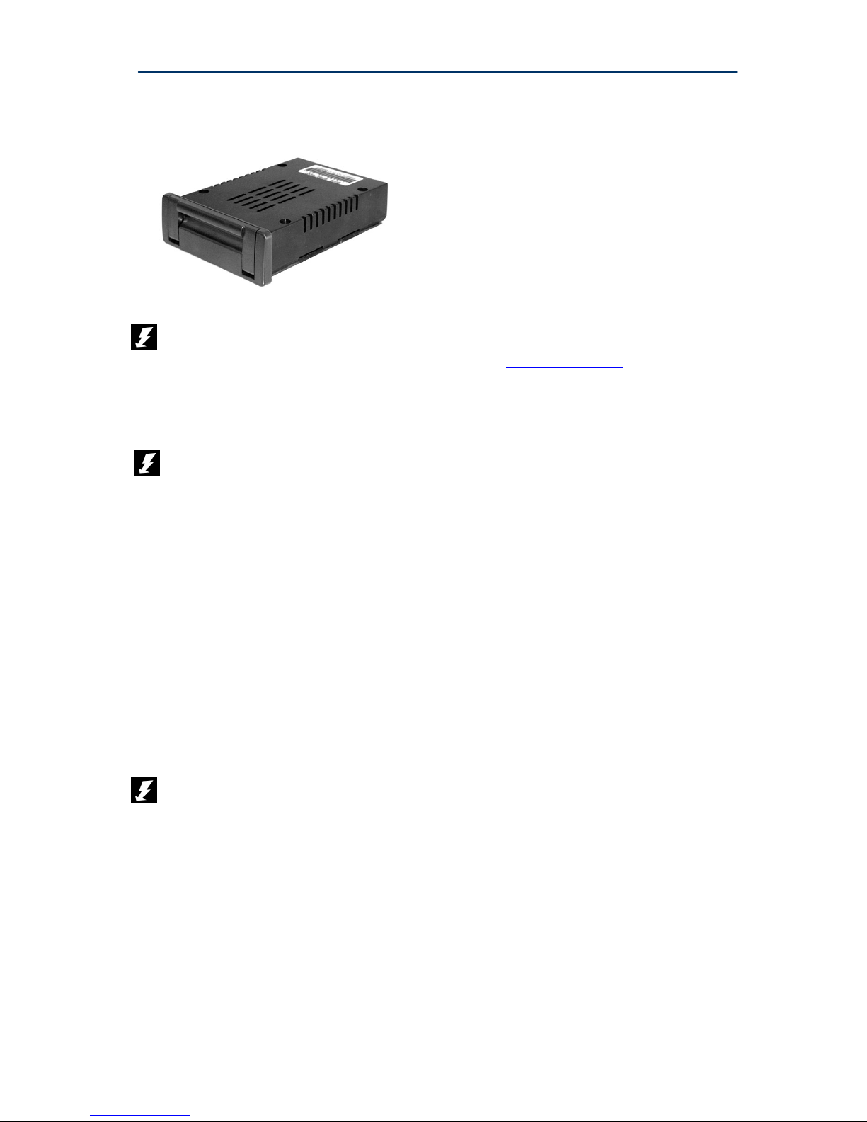
the MR recorder series’ removable disk
Please ask your system integrator or the
manufacturer about the sizes and models
currently available.
Only remove the hard disk when all the LEDs on the front of the device are off! Removing the
hard disk before the LEDs go out results in damage to the device. All warranties and
guarantees are thereby invalidated!

DResearch – User Manual TeleObserver MR3140 2011-02-03
17
2.3 Significance of the status LEDs
On the front of the unit there are four coloured LEDs which indicate the current status of the device.
At any time you can determine the current status of the device from the colour codes. We recommend
that you print out the following table and keep it with your service documents.
LED State Description
off
device is switched off
green device is ready for operation
orange device is booting or shutting down
Status
(state of the device)
red Error – contact the service department!
off device is not recording
green actively recording into the ring archive (normal)
orange actively recording into the alarm archive (alarm event)
orange
flashing
HD will be deleted and adopted by the device in 30 seconds
HD
(recording)
red hard disk is not available or could not be recognised/adopted by the
device
no recording on the hard disk
other errors
off no connection between PC and device
green active data transmission, connection between PC and device
orange not busy
Link
(LAN-connection)
red Error – no communication
off archives cannot be recognised (fault)
green 0% - 60% of the capacity full
orange > 60% - 80% of the capacity full
Archive
(archive fill level)
red > 80% - 100% of the capacity full
The codes listed here could be changed by the manufacturer. If in doubt contact your system
integrator or the manufacturer.

DResearch – User Manual TeleObserver MR3140 2011-02-03
18
2.4 Device interfaces
2.4.1 Analogue video inputs 1 ... 4 – connection of analogue CCTV cameras
Up to four standard commercial CCTV cameras can be connected via the BNC connections IN 1 to
IN 4 (rear of device) provided they have BNC connectors and deliver an analogue CCIR standard
(CVBS, PAL/NTSC) signal. The operating voltage for the cameras is provided by the MR3140
recorder itself (12V).
Before video footage can be recorded from a camera (analogue and IP), video recording for this
camera has to be explicitly activated in the Central Monitoring Software (see configuration chapter).
Note that you can only ensure a stable camera power supply of 12 V if the power supply to the
recorder is always over 13V.
2.4.2 LAN Interface – connection of IP network cameras or other devices
Pin Name Description
1 Tx+ Transceive Data+
2 Tx- Transceive Data3 Rx+ Receive Data+
4 Not used
5 Not used
6 Rx- Receive Data7 Not used
8 Not used
This interface supports a bandwidth of 100 Mbit
Pinout of the RJ45 network interface
Using the RJ45-interface (LAN, Ethernet) and a patch cable (CAT 5 or higher) you can connect the
device with other external devices. This might be:
A computer - for configuration and/or control through the CMS
External devices - such as a WLAN-modem, a switch, a single IP-camera
or several IP-cameras over a switch
Connection of IP-cameras
Up to 12 IP cameras can be connected via the LAN interface and an external switch (see system
diagram on page 4). Video recording can be activated for up to 8 IP cameras, the remainder can be
set up in parallel to provide video pictures on a monitor.
Please note that the device does not support Power over Ethernet (PoE). Depending on the type of
cameras used (e.g. AXIS 209 FD-R) their power supply has to come via a separate power supply
unit or the PoE supply belonging to the external switch. Consult the relevant camera manual for
power supply details.
Only use DResearch recommended accessories!

DResearch – User Manual TeleObserver MR3140 2011-02-03
19
2.4.3 Video Out 1 and 2 – connection of control monitors
Two control monitors for monitoring the cameras can be connected in parallel via the recorder’s
analogue video outputs. This enables the camera pictures to be viewed in two different locations.
The cameras to be displayed on the monitors can be configured in the SystemManagement software
module. All 4 analogue and up to 12 IP cameras can be displayed using a video switcher and/or in
multi-view (single, quad, nona etc.). The position of the individual camera signals/video pictures within
the screen and the switching sequence can be individually configured.
It is not necessary for the relevant camera to be activated for recording in order to display video
pictures. Although only 8 IP cameras can be activated for recording, up to 12 IP cameras can be
connected to the recorder via the external switch and all 12 video signals can be displayed.
Please note that displaying video makes additional demands on the device. Too many video
signals can lead to reduced frame rates and hesitation in playback on the video OUT. Because of
this only set those cameras for video OUT which are absolutely necessary. Usually it makes
sense only to set up those cameras which cover sensitive areas (vehicle entry area or rear view
camera).
A suitable monitor is available directly from DResearch. Please look at our current product catalogue
or contact us.
2.4.3.1 Sequential video output and multiviews
Live pictures from the linked cameras can be switched through in sequence to be shown on the
control monitor – this is controlled via a digital input. Configuration is dealt with in full in chapter 3.

DResearch – User Manual TeleObserver MR3140 2011-02-03
20
2.4.3.2 Display of information and system events (OSD)
Using OnScreenDisplay the recorder shows additional information in the form of symbols and texts
when particular system events and alarms occur. The following information and system events are
displayed:
Symbol Significance Description
Name of the warning device
Symbols for the six digital inputs IN1 to IN6.
Displays the number of the active alarm or
electromechanical lock at the bottom of the
screen.
⊗ -
Alarm in the last hour.
Automatically increases the duration if another
alarm is activated or deactivated within this
period.
* Alarm recording active
Alarm sequence recording.
HD (!) No disk found
No disk or disk faulty.
HD (60%)
HD (80%)
Alarm archives 60% full
Alarm archives 80% full
At least 60% (or 80%) of the hard disk
capacity has been written with alarm footage.
HD (full) Alarm archives full
No further alarm sequence recording possible.
Archiving and release of the alarm archive in
ImageFinder.
GPS GPS fault
Device is not receiving GPS signal.
IBIS IBIS-Bus fault
Device is not receiving IBIS signal.
RMC RMC fault
Fault in the Rail Media Coupler.
IP (1..8) Camera number IP camera video signal missing.
A (1..4) Camera number Analogue camera video signal missing or
camera has been sabotaged or covered.
(A = camera group A = 1..4)
Alarm system conditions and events indicators
 Loading...