

Page 1
User Manual
ConBee
Document Version V1.0
2016-06-15
Page 2

User Manual
Version 1.0
2016-06-15
ConBee - USB Dongle
www.dresden-elektronik.de
Page 2 of 25
Table of contents
1. Overview ......................................................................................................................... 6
2. Applications ................................ ................................................................ ..................... 6
3. Features .......................................................................................................................... 6
3.1. Short facts .............................................................................................................. 6
3.2. How does the USB Dongle work? ........................................................................... 7
4. Quick start ....................................................................................................................... 8
4.1. Content of delivery.................................................................................................. 8
4.2. Requirements ......................................................................................................... 8
4.2.1. Supported Operating Systems .................................................................... 8
4.3. Installing drivers ..................................................................................................... 8
4.3.1. Windows ..................................................................................................... 8
4.3.2. Linux 9
4.3.3. Mac OS X ................................................................................................... 9
4.4. Using the USB Dongle with deCONZ application .................................................... 9
4.4.1. Windows ..................................................................................................... 9
4.4.2. Raspbian Linux ........................................................................................... 9
4.4.3. Ubuntu Linux ............................................................................................. 10
4.4.4. Mac OS X ................................................................................................. 10
5. Installing individual firmware with GCFFlasher .............................................................. 11
5.1. Windows ............................................................................................................... 11
5.2. Raspbian Linux ..................................................................................................... 11
5.3. Ubuntu Linux ........................................................................................................ 12
5.4. Mac OS X ............................................................................................................. 12
5.5. Notes on custom firmware .................................................................................... 12
5.6. Example with BitCatcher ...................................................................................... 12
5.6.1. Software .................................................................................................... 13
5.6.2. Firmware ................................................................................................... 13
5.7. EEPROM layout ................................................................................................... 13
5.8. Fuse setting .......................................................................................................... 13
6. Technical data ............................................................................................................... 13
6.1. Output power and channel settings ...................................................................... 16
Page 3

User Manual
Version 1.0
2016-06-15
ConBee - USB Dongle
www.dresden-elektronik.de
Page 3 of 25
7. Pin assignment .............................................................................................................. 17
8. Hardware modifications for development ....................................................................... 19
8.1. Assemble the program header ............................................................................. 19
8.2. Assemble the trace header ................................................................................... 19
8.3. Assemble the Serial Flash Memory ...................................................................... 20
8.4. Assemble the User button .................................................................................... 20
8.5. Assemble the status LEDs .................................................................................... 21
9. Radio certification .......................................................................................................... 22
9.1. United States (FCC) ............................................................................................. 22
9.2. European Union (ETSI) ........................................................................................ 22
9.3. Approved antenna list ........................................................................................... 23
10. Ordering information ...................................................................................................... 23
11. Revision notes ............................................................................................................... 23
12. References ................................................................................................ .................... 24
Page 4
User Manual
Version 1.0
2016-06-15
ConBee - USB Dongle
www.dresden-elektronik.de
Page 4 of 25
Date
Version
Description
2016-06-15
1.0
Initial version
Document history
Page 5
User Manual
Version 1.0
2016-06-15
ConBee - USB Dongle
www.dresden-elektronik.de
Page 5 of 25
Abbreviation
Description
IEEE 802.15.4
Communication standard, applicable to low-rate Wireless Personal Area
Networks (WPAN)
CE
Consumer Electronics
ETSI
European Telecommunications Standards Institute
FCC
Federal Communications Commission
GPIO
Generals Purpose Input Output
JTAG
Joint Test Action Group, digital interface for debugging of embedded
devices, also known as IEEE 1149.1 standard interface
MAC
Medium (Media) Access Control
MCU, µC
Microcontroller Unit
OS
Operating System
RF
Radio Frequency
RPi
Raspberry Pi, a famous inexpensive single board computer in credit card
size
R&TTE
Radio and Telecommunications Terminal Equipment
(Directive of the European Union)
U[S]ART
Universal [Synchronous/]Asynchronous Receiver Transmitter
ZigBee
Low-cost, low-power wireless mesh network standard. The ZigBee Alliance
is a group of companies that maintain and publish the ZigBee standard.
ZHA
ZigBee Home Automation profile
ZLL
ZigBee Light Link profile
Abbreviations
Page 6

User Manual
Version 1.0
2016-06-15
ConBee - USB Dongle
www.dresden-elektronik.de
Page 6 of 25
1. Overview
The ConBee is the platform independent USB Dongle that turns your host into a full
functional wireless node which can be seamlessly integrated into ZigBee networks. This will
enhance the application range of your host with monitoring and controlling ZigBee networks.
ZigBee compatible devices are available from a lot of manufacturers.
This USB Dongle contains a powerful radio module with integrated power amplifier and low
noise amplifier. Together with the assembled onboard chip antenna which has been
optimally tuned ensures a superior RF performance.
The ConBee is shipped with a bootloader application for simple firmware uploads and
updates.
The ZigBee firmware is interfaced by a software called deCONZ which runs on Windows,
Linux and Mac OS X and is responsible for ZigBee network control and monitoring.
Basically, the USB Dongle is a reference design for the ZigBee radio module deRFmega25623M12 by dresden elektronik.
2. Applications
Mainly the ConBee is designed to handle ZigBee Light Link (ZLL) and ZigBee Home
Automation (ZHA) applications in connection with the ZigBee firmware and software
deCONZ. A more detailed description of the ZLL standard, the features, benefits and
available certified products can be found on the official alliance website [1].
It is also possible to use a custom firmware for wireless applications. Follow the instructions
in Section 5 and Section 10 for detailed instructions on software installation and customer
modifications.
Note: Please note that depending on the modifications the radio certification and
compliance may become invalid. Please get in contact with us to advise you
for a custom FCC certified and/or compliant design.
3. Features
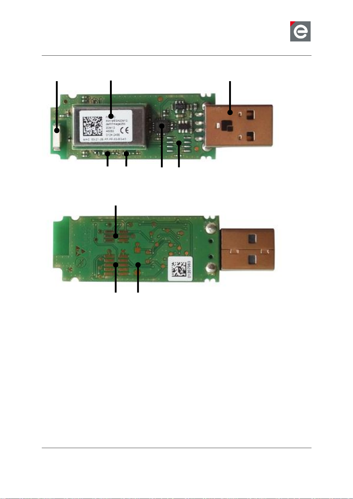
The ConBee contains the features listed below. Figure 1 illustrates the feature parts in a
detailed view.
3.1. Short facts
Slim size: 70.7 x 23.0 x 8.3 mm
Supply voltage: USB powered 5.0V / DC
Onboard 2.4 GHz ZigBee radio module „deRFmega256-23M12‟
Application interfaces: USB
Page 7
User Manual
Version 1.0
2016-06-15
ConBee - USB Dongle
www.dresden-elektronik.de
Page 7 of 25
Radio module
Chip antenna
USB connector
Flash (n.a.)
LEDs (n.a.)
FTDI
UART (n.a.)
JTAG (n.a.)
Button (n.a.)
n.a.: not assembled
Figure 1: ConBee in detail
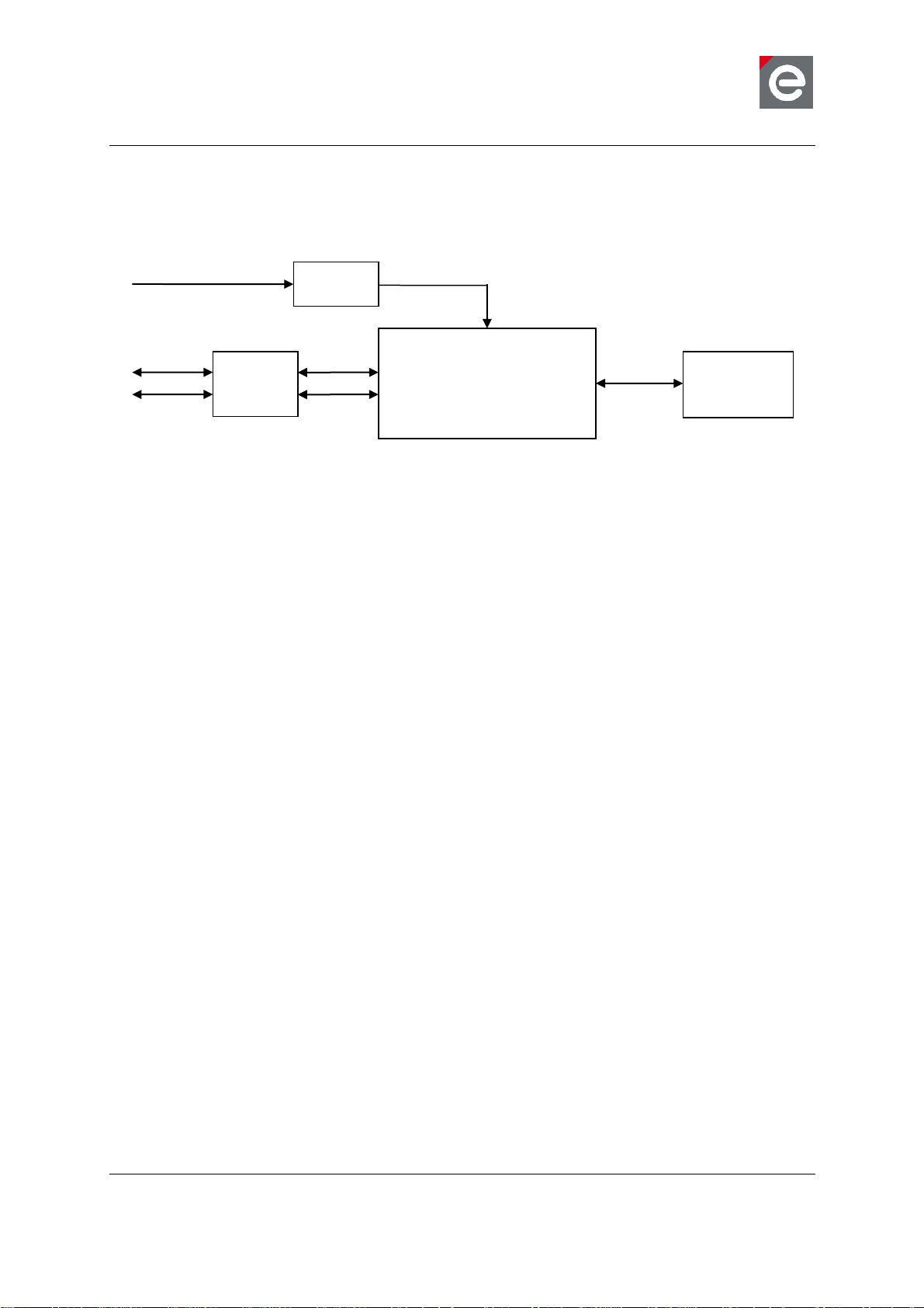
3.2. How does the USB Dongle work?
The functional parts of the ConBee are shown in a schematic overview in Figure 2.
The USB Dongle will be supplied by the USB 5.0 V domain. Therefore the USB power supply
must be sufficient to support the additional load. An onboard low-drop-out voltage regulator
generates a stable 3.3 V voltage to supply the radio module on the USB Dongle.
The onboard placed radio module deRFmega256-23M12 by dresden elektronik contains an
8-bit AVR microcontroller with an integrated low-power 2.4 GHz transceiver for ZigBee and
IEEE 802.15.4 applications. The ConBee has no pre-installed firmware. You can install the
firmware that fits your needs. Each USB Dongle contains a world-wide unique identifier,
named MAC-ID. It consists of an 8 byte address, including the vendor ID and product ID. The
MAC-ID is stored in the MCU internal EEPROM.
Page 8
User Manual
Version 1.0
2016-06-15
ConBee - USB Dongle
www.dresden-elektronik.de
Page 8 of 25
USB
UART
FTDI
Chip Ant.
LDO
VUSB
4.5V to 5.5V
RFOUT2
VOUT
3.3V
The RF output signal of the 2.4 GHz radio module is routed to the assembled onboard chip
antenna.
deRFmega256-23M12
Figure 2: Block Diagram
4. Quick start
This section describes in short steps a fast start-up of the ConBee to control and monitor a
ZigBee network.
4.1. Content of delivery
One shipped USB Dongle package contains the following:
1x ConBee - USB Dongle
1x Instruction leaflet
4.2. Requirements
The ConBee needs a dedicated USB port with up to 500mA current supply and works on
desktop PCs, laptops and the Single Board Computer Raspberry Pi 1, 2 and 3.
4.2.1. Supported Operating Systems
Microsoft Windows 7, 8, 8.1 and 10
Canonical Ubuntu Linux 16.04
Raspberry Pi Raspian Wheezy and Jessie
Apple Mac OS X 10.11
4.3. Installing drivers
On most platforms the necessary USB COM port drivers by FTDI will be installed
automatically when you plug in the USB Dongle. You can also download and install the FTDI
drivers manually from http://www.ftdichip.com/FTDrivers.htm
4.3.1. Windows
Plug in the USB Dongle into a free USB port. On Windows the drivers will be installed
automatically if you have activated automatic driver installation. A window will pop up where
you can select automatic driver installation.
Page 9

User Manual
Version 1.0
2016-06-15
ConBee - USB Dongle
www.dresden-elektronik.de
Page 9 of 25
1
4.3.2. Linux
No further driver installation is needed. All common Linux distributions include the necessary
COM port drivers.
4.3.3. Mac OS X
No further driver installation is needed. Mac OS X includes the necessary COM port drivers.
4.4. Using the USB Dongle with deCONZ application
The deCONZ1 application allows the configuration, operation, monitoring and maintenance of
ZigBee networks.
4.4.1. Windows
1. Download and install the deCONZ software from:
https://www.dresden-elektronik.de/funktechnik/products/software/pc/deconz/
Important Note:
The next step will bring up a windows firewall warning. This happens because deCONZ
runs a webserver to provide the WebApp and is using a discovery mechanism via
Internet so that your devices can find the WebApp. For proper operation it‟s required to
confirm the firewall exception.
2. Start the deCONZ application from the start menu.
3. The application automatically connects to the USB Dongle and a blue coordinator node
with address 0x0000 appears.
4. In a browser navigate to http://www.dresden-elektronik.de/discover/
5. Login as user: delight and password: delight
For further instructions on the WebApp refer to the Quick Start Guide [3].
4.4.2. Raspbian Linux
4.4.2.1. Required software packages
1. Download and install Qt 4.8
$ sudo apt-get install libqt4-core
4.4.2.2. Download and install deCONZ
1. Download deCONZ software package:
$ wget http://www.dresden-elektronik.de/rpi/deconz/stable/deconzlatest.deb
2. Install deCONZ software package:
$ sudo dpkg -i deconz-latest.deb
4.4.2.3. Start and run the application
1. If not already running start the desktop environment
See https://www.dresden-elektronik.de/funktechnik/products/software/pc-software/deconz/?L=1
Page 10

User Manual
Version 1.0
2016-06-15
ConBee - USB Dongle
www.dresden-elektronik.de
Page 10 of 25
$ startx
2. Start the deCONZ application via start menu
Menu / Programming /deCONZ
3. In a browser navigate to http://www.dresden-elektronik.de/discover/
4. Login as user: delight and password: delight
For further instructions on the WebApp refer to the Quick Start Guide [3].
4.4.2.4. Execute the application at start-up
1. Create the folder “autostart”:
$ mkdir -p /home/pi/.config/autostart/
2. Create and edit the file “deCONZ.desktop”:
$ nano /home/pi/.config/autostart/deCONZ.desktop
3. Insert the following lines and save the file:
[Desktop Entry]
Type=Application
Name=deCONZ
Exec=deCONZ-autostart.sh
StartupNotify=false
Now, the application will run automatically after start-up of the Raspberry Pi.
4.4.3. Ubuntu Linux
1. Download the deCONZ (Ubuntu Linux) software from:
https://www.dresden-elektronik.de/funktechnik/products/software/pc/deconz
2. In the file manager right click on the downloaded .deb file and chose “Open With / Ubuntu
Software Center”. In the software center click on the install button.
3. Start the deCONZ application from the applications menu.
4. The application automatically connects to the USB Dongle and a blue coordinator node
with address 0x0000 appears.
5. In a browser navigate to http://www.dresden-elektronik.de/discover/
6. Login as user: delight and password: delight
For further instructions on the WebApp refer to the Quick Start Guide [3].
4.4.4. Mac OS X
1. Download the deCONZ (OS X) software from:
https://www.dresden-elektronik.de/funktechnik/products/software/pc/deconz
2. Unzip the package and drag the deCONZ.app file to applications folder.
3. For the first start you need to right click the deCONZ application in Finder and chose
open. After that deCONZ can be started from Launchpad.
Page 11

User Manual
Version 1.0
2016-06-15
ConBee - USB Dongle
www.dresden-elektronik.de
Page 11 of 25
4. The application automatically connects to the USB Dongle and a blue coordinator node
with address 0x0000 appears.
5. In a browser navigate to http://www.dresden-elektronik.de/discover/
6. Login as user: delight, password: delight
For further instructions on the WebApp refer to the Quick Start Guide [3].
5. Installing individual firmware with GCFFlasher
GCFFlasher is a command line tool which can be used to update the USB Dongle without
additional programming hardware. It is also used by deCONZ to update the ZigBee firmware.
The GCFFlasher communicates with the USB Dongle bootloader via COM port interface.
Note 1: GCFFlasher accepts firmware files in binary file format (.bin) and in dresden
elektronik‟s proprietary GCF file format. There is no EEPROM programming
support within GCFFlasher. EEPROM programming must be done within your
application code. Please note that modifying the EEPROM may cause
irreversibly damage to your USB Dongle. Use with care. GCFFlasher also
provides the option „-r‟ to power cycle the target device.
Note 2: It is not possible to perform the update while running the deCONZ application.
Therefore it is necessary to close the deCONZ application before updating the
firmware with GCFFlasher.
Note 3: For help on the GCFFlasher options run: GCFFlasher -h
5.1. Windows
1. Download GCFFlasher (Windows) from:
https://www.dresden-elektronik.de/funktechnik/service/downloads/software
2. Unzip the package and double click the GCFFlasherCommandline.bat file. A command
prompt will open and output a list of all connected device(s).
3. Put the firmware file in the same folder as GCFFlasher.exe
4. To upload the firmware, invoke GCFFlasher from the command prompt as follows:
GCFFlasher –d <device> -f <YourApplication.bin[.GCF]>
For example:
GCFFlasher –d 0 –f deCONZ_0x26050500.bin.GCF
Note: You can list the devices with: GCFFlasher –l
5.2. Raspbian Linux
1. Download GCFFlasher
$ wget http://www.dresdenelektronik.de/rpi/gcfflasher/gcfflasher-latest.deb
2. Install GCFFlasher
$ sudo dpkg -i gcfflasher-latest.deb
3. To upload the firmware, invoke GCFFlasher (superuser rights required) as follows:
Page 12

User Manual
Version 1.0
2016-06-15
ConBee - USB Dongle
www.dresden-elektronik.de
Page 12 of 25
$ sudo GCFFlasher –d <device> -f <YourApplication.bin[.GCF]>
For example:
$ sudo GCFFlasher –d 0 –f deCONZ_0x26050500.bin.GCF
Note: You can list all devices with: $ sudo GCFFlasher –l
5.3. Ubuntu Linux
1. Download GCFFlasher (Ubuntu Linux) from:
https://www.dresden-elektronik.de/funktechnik/service/downloads/software
2. In the file manager right click on the downloaded .deb file and chose “Open With / Ubuntu
Software Center”. In the software center click on the install button.
3. To upload the firmware, invoke GCFFlasher (superuser rights required) as follows:
$ sudo GCFFlasher –d <device> -f <YourApplication.bin[.GCF]>
For example:
$ sudo GCFFlasher –d 0 –f deCONZ_0x26050500.bin.GCF
Note: You can list all devices with: $ sudo GCFFlasher –l
5.4. Mac OS X
1. Download GCFFlasher (OS X) from:
https://www.dresden-elektronik.de/funktechnik/service/downloads/software
2. In Finder unzip the package by double click on it.
3. Put the firmware file in the unzipped folder
4. Open a terminal and cd into the GCFFlasher folder
5. To upload the firmware, invoke GCFFlasher from the command line as follows:
$ sudo GCFFlasher –d <device> -f <YourApplication.bin[.GCF]>
For example:
$ sudo GCFFlasher –d 0 –f deCONZ_0x26050500.bin.GCF
Note: You can list all devices with: $ sudo GCFFlasher –l
5.5. Notes on custom firmware
When using the JTAG interface, do not modify sensitive EEPROM areas like Bootloader
control section, ZigBee firmware settings, NV-section containing i.e. MAC address, unless
you are absolutely sure what you are doing.
Please also note that dresden elektronik will neither provide firmware images of the
bootloader nor support restoring the bootloader or EEPROM once overwritten.
5.6. Example with BitCatcher
BitCatcher is a software tool for analyzing wireless transmissions in ZigBee based networks
and allows the monitoring of complex network structures as well as observe data flows and
runtime performance in detail without additional effort.
Page 13
User Manual
Version 1.0
2016-06-15
ConBee - USB Dongle
www.dresden-elektronik.de
Page 13 of 25
EEPROM sections
address range
content / remark
0x0000 ... 0x00FF
Bootloader specific
0x0100 ... 0x1EFF
user available
0x1F00 ... 0x1FDF
ZigBee firmware specific
0x1FE0 ... 0x1FFF
NV-section
Fuse bytes
Setting
Description
EXTENDED
0xF8
Extended fuse byte
HIGH
0x90
Fuse high byte
LOW
0xCE
Fuse low byte
5.6.1. Software
1. Download and install the Luxoft BitCatcher ZigBee Network Analyzer from:
http://www.luxoft.com/embedded-systems-development/bitcatcher
5.6.2. Firmware
1. Download the BitCatcher firmware for ConBee from:
https://www.dresden-elektronik.de/funktechnik/service/downloads/software/
2. Execute the steps of section 5.1, 5.2 and 5.3 depending on your operating system.
5.7. EEPROM layout
The radio module contained on the ConBee uses the following EEPROM sections. If
developing custom firmware, please do not modify the sections already used.
Table 1: EEPROM sections
5.8. Fuse setting
The table below shows the recommended fuse byte settings for the ConBee which the board
also comes with in factory new condition. Please refer to the radio module user manual [4]
for their description and alternative configurations.
Table 2: Fuse settings
6. Technical data
The USB Dongle contains the 2.4 GHz IEEE 802.15.4 radio module „deRFmega256-23M12‟
by dresden elektronik. A detailed description of the module‟s characteristics and properties
can be found in the radio module user manual [4].
Page 14

User Manual
Version 1.0
2016-06-15
ConBee - USB Dongle
www.dresden-elektronik.de
Page 14 of 25
Mechanical data
Value
Descriptor
Parameter
Min
Typ
Max
Unit
Size
L
70.7
mm
W
23.0
mm
H
8.3
mm
Temperature range
Value
Descriptor
Parameter
Min
Typ
Max
Unit
Working
temperature
T
work
-40
+25
+85
°C
Absolute maximum ratings
Value
Descriptor
Parameter
Min
Typ
Max
Unit
Supply voltage
V
in_max
T=25°C
5.5 V Supply current
I
in_max
TX_ON, TX_PWR=0x0
215
mA
Electrical characteristics
Value
Descriptor
Parameter
Min
Typ
Max
Unit
Supply voltage
Vin 4.5
5.0
5.5
V
Supply current
I
in_trxoff
Vin=5.0 V (only Bootloader)
5.5
mA
Table 3: Mechanical data
Table 4: Temperature range
Table 5: Absolute maximum ratings
Note: Stresses beyond those listed under “Absolute maximum ratings” may cause
permanent damage to the device. This is a stress rating only and functional
operation of the device at these or any other conditions beyond those
indicated in the operational sections of this manual are not implied. Exposure
to absolute maximum rating conditions for extended periods may affect device
reliability. For more details about these parameters, refer to individual
datasheets of the components used.
Table 6: Electrical characteristics
Page 15
User Manual
Version 1.0
2016-06-15
ConBee - USB Dongle
www.dresden-elektronik.de
Page 15 of 25
I
in_txon
Vin=5.0 V, TX_PWR=0xE
Vin=5.0 V, TX_PWR=0xF
59
48
mA
mA
MCU clock
Value
Descriptor
Parameter
Min
Typ
Max
Unit
MCU clock
CLK
MCU
8 MHz
Radio characteristics
Value
Descriptor
Parameter
Min
Typ
Max
Unit
Antenna
ANT1
Type
Chip Ceramic
Gain
-0.7
dBi
Coaxial connector
COAX
Type
U.FL
Frequency range
F
range_EU
PHY_CC_CCA = 0x0B..0x1A
2405
2480
MHz
F
range_US
PHY_CC_CCA = 0x0B..0x19
2405
2475
MHz
Channels
CH
_EU
PHY_CC_CCA = 0x0B..0x1A
16
CH
_US
PHY_CC_CCA = 0x0B..0x19
15
Absolute TX power
POUT
Vin=5.0 V, TX_PWR=0xE
Vin=5.0 V, TX_PWR=0xF
8.7
3.9
dBm
dBm
Receiver sensitivity
SENS
Data Rate = 250 kBit/s
Data Rate = 500 kBit/s
Data Rate = 1000 kBit/s
Data Rate = 2000 kBit/s
-105
-101
-99
-94
dBm
dBm
dBm
dBm
Data rate (gross)
DR
TRX_CTRL_2 = 0x00
TRX_CTRL_2 = 0x01
TRX_CTRL_2 = 0x02
TRX_CTRL_2 = 0x03
250
500
1000
2000
kbps
kbps
kbps
kbps
Table 7: MCU clock
Table 8: Radio characteristics
Page 16

User Manual
Version 1.0
2016-06-15
ConBee - USB Dongle
www.dresden-elektronik.de
Page 16 of 25
Device
ConBee
Region
ETSI (EU)
FCC (US)
Channel
TX_PWR
TX_PWR
11
0xF
0xE
12
0xF
0xE
13
0xF
0xE
14
0xF
0xE
15
0xF
0xE
16
0xF
0xE
17
0xF
0xE
18
0xF
0xE
19
0xF
0xE
20
0xF
0xE
21
0xF
0xE
22
0xF
0xE
23
0xF
0xE
24
0xF
0xE
25
0xF
0xF
26
0xF
Not used
6.1. Output power and channel settings
The ConBee is able to provide an output power greater than 10 dBm. Table 9 defines the
power settings of the TX_PWR register [4], which must be set to fulfill all national
requirements of Europe (EN 300 328) and the United States (CFR 47 Ch. I FCC Part 15).
Note: Channel 26 must be deactivated for using the USB Dongle in the United
States to fulfill the band edge requirements of FCC Part 15 Subpart C §
15.247.
Table 9: Output power settings
Page 17

User Manual
Version 1.0
2016-06-15
ConBee - USB Dongle
www.dresden-elektronik.de
Page 17 of 25
Signal pin description of assembled radio module deRFmega256-23M12
Radio module pin
Signal
Function
Comment
28
PE0/RXD0
UART RX 0
Communication interface to FTDI
29
PE1/TXD0
UART TX 0
Communication interface to FTDI
30
PE2/XCK0
CTS
Communication interface to FTDI
4
RESET
Reset
10k pull-up onboard, low-active,
Connected to CBUS0 of FTDI
27
PB7
SW1
Button to GND (NA)
15
PD7
LED1
Red, low-active (NA)
8
PG2
LED2
Green, low-active (NA)
57
RFOUT1
RF out signal 1
terminated with 49R9 resistor
53
RFOUT2
RF out signal 2
Chip antenna
48
PF4/TCK
JTAG
NA
47
PF5/TMS
JTAG
NA
46
PF6/TDO
JTAG
NA
45
PF7/TDI
JTAG
NA
13
PD2/RXD1
UART RX 1
NA
12
PD3/TXD1
UART TX 1
NA
20
PB0/SS
Chip Select
Serial Flash Memory (NA)
21
PB2/MOSI
Serial Data In
Serial Flash Memory (NA)
22
PB1/SCK
Serial Clock
Serial Flash Memory (NA)
23
PB3/MISO
Serial Data Out
Serial Flash Memory (NA)
7. Pin assignment
This section lists all available signals and their function on the USB Dongle.
Note: The signal NC means Not Connected. NA means Not Assembled.
Table 10: Signal pin description
Page 18

User Manual
Version 1.0
2016-06-15
ConBee - USB Dongle
www.dresden-elektronik.de
Page 18 of 25
-
VBUS
Voltage supply
5 V supplied by USB port
2, 50
VCC
Voltage supply
3.3 V generated internally
1, 31, 44, 49, 51
GND
Ground
System ground
Header pin description
Header
Pin
Signal
Comment
Program
(not assembled)
1
TCK
JTAG
2
GND
3 TDO
JTAG
4
VCC
3.3 V generated internally
5
TMS
JTAG
6
RESET
Reset signal for ZigBee USB
Gateway
7
VCC
3.3 V generated internally
8
NC 9
TDI
JTAG
10
GND
Trace
(not assembled)
1
TXD1
UART
2
VCC
3.3 V generated internally
3
NC
4
RXD1
UART
5
NC 6
GND
Table 11: Header pin description
Page 19
User Manual
Version 1.0
2016-06-15
ConBee - USB Dongle
www.dresden-elektronik.de
Page 19 of 25
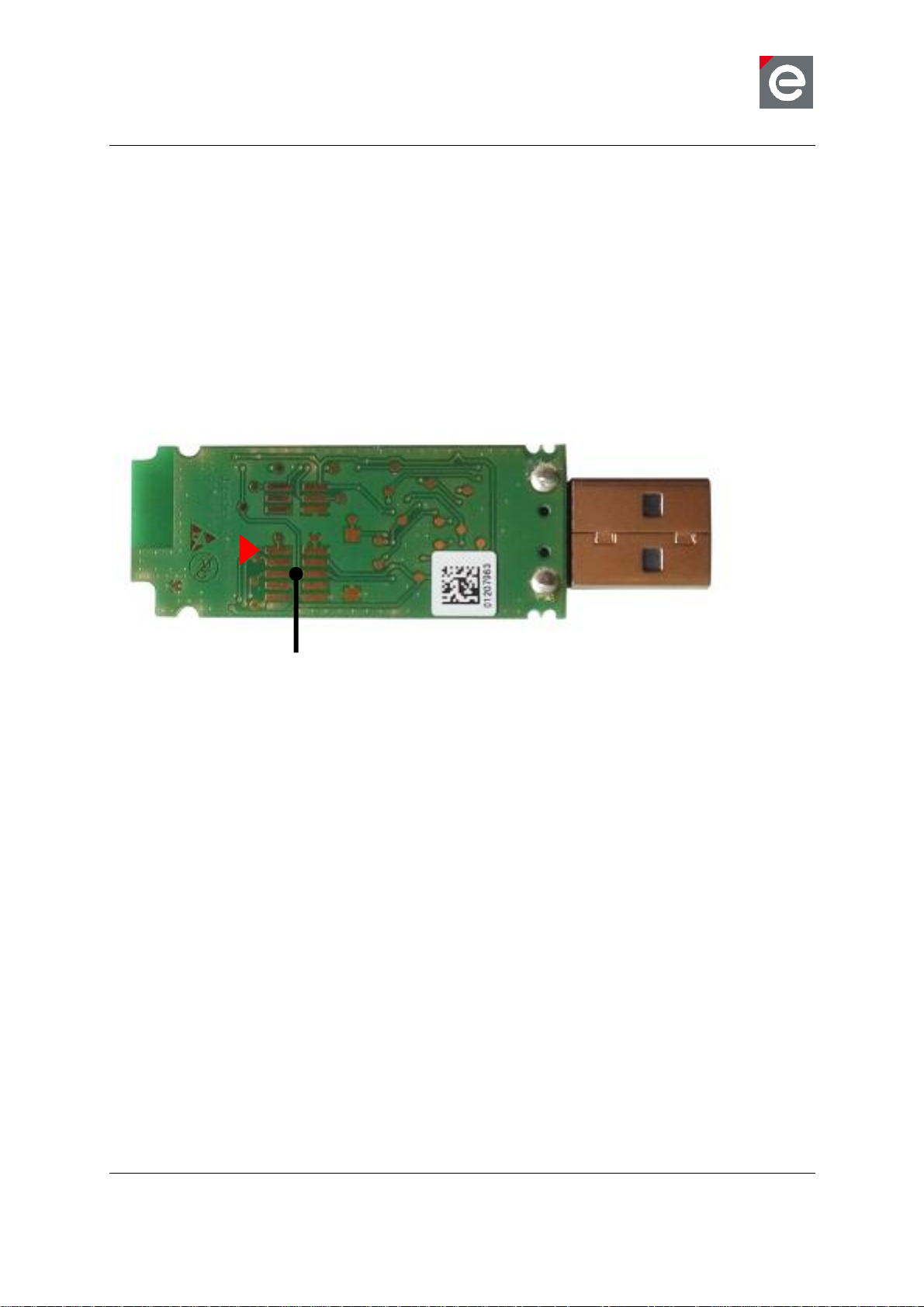
Program header footprint
8. Hardware modifications for development
Besides the factory-default USB Dongle configuration it is also possible to modify the
hardware to enhance its functionality.
8.1. Assemble the program header
The program header provides the microcontroller programming interface of the radio module.
Assemble a 50 mil 10-pin SMT header on the bottom side. We recommend the use of the
header FTSH-105-04-LM-DV-P by SAMTEC or a similar item.
The header pin description can be found in Section 8 Table 11 . A detailed description of
suitable programmers and related software tools are listed in [5].
Figure 3: USB Dongle program header position (default not assembled)
Note: Improper handling in respect of erasing or overwriting the MCU internal flash
or EEPROM completely or in parts may result in an unusable USB Dongle
unit. Modification of the pre-allocated EEPROM memory sections or removal
of the pre-installed bootloader will irreversibly preclude restoring, booting or
upgrading the shipping firmware at all. dresden elektronik will not support such
modifications (see Section 5.3 for details).
8.2. Assemble the trace header
The trace header provides the microcontroller UART interface of the radio module. Assemble
a 50 mil 6-pin SMT header on the bottom side. We recommend the use of the header FTSH103-01-F-DV by SAMTEC or a similar item.
The header pin description can be found in Section 8 Table 11.
Page 20

User Manual
Version 1.0
2016-06-15
ConBee - USB Dongle
www.dresden-elektronik.de
Page 20 of 25
Trace header footprint
Serial Flash Memory footprint
Stabilizing capacitor
Figure 4: USB Dongle trace header position (default not assembled)
8.3. Assemble the Serial Flash Memory
The USB Dongle offers the use of an external Serial Flash Memory for custom application or
features. The memory interface is connected to the SPI of the radio module. The provided
footprint is SO-8. We recommend the use of a Serial Flash Memory like M25P40-VMN6TPB
by MICRON. It is useful to place a stabilizing capacitor of 100nF to the 0402 footprint next to
the memory.
The signal pin description can be found in Section 8 Table 10.
Figure 5: USB Dongle Serial Flash Memory position (default not assembled)
8.4. Assemble the User button
The USB Dongle offers the use of an external user button. We recommend the use of the
SMT button KSR211GLFS by ITT or similar items. The button is connected with ground and
signal PB7.
The signal pin description can be found in Section 8 Table 10Table 11.
Page 21

User Manual
Version 1.0
2016-06-15
ConBee - USB Dongle
www.dresden-elektronik.de
Page 21 of 25
User button footprint
Red LED
Series resistor
Series resistor
Green LED
Figure 6: USB Dongle user button position (default not assembled)
8.5. Assemble the status LEDs
The USB Dongle offers the use of two status LEDs. The first LED is connected with signal
PD7 and the second LED is connected with signal PG2. Each LED needs one additional
series resistor with a value of 820 Ohms. Both LEDs are low-active. We recommend the use
of the following LEDs and resistors:
Red low current LED: TLMS1000-GS08 by Vishay (SMT package 0603)
Green low current LED: LG L29K-G2J1-24-Z by OSRAM (SMT package 0603)
Resistor 820 Ohms: RC0402FR-07820RL by YAGEO (SMT package 0402)
The signal pin description can be found in Section 8 Table 10.
Figure 7: USB Dongle status LEDs (default not assembled)
Page 22

User Manual
Version 1.0
2016-06-15
ConBee - USB Dongle
www.dresden-elektronik.de
Page 22 of 25
9. Radio certification
9.1. United States (FCC)
The ConBee contains the radio module „deRFmega256-23M12‟, which is certified according
to FCC part 15. The FCC-ID of the radio module deRFmega256-23M12 is printed on a
visible permanently affixed label on the top of the module‟s RF shielding.
This product contains FCC ID: XVV-MEGA23M12
This equipment complies with Part 15 of the FCC Rules. Operation is subject to the following
two conditions: (1) this device may not cause harmful interference, and (2) this device must
accept any interference received, including interference that may cause undesired operation
(FCC 15.19). The internal / external antenna(s) used for this mobile transmitter must provide
a separation distance of at least 20 cm from all persons and must not be co-located or
operating in conjunction with any other antenna or transmitter.
Modifications not expressly approved by the manufacturer could void the user's authority to
operate this equipment (FCC section 15.21).
This equipment has been tested and found to comply with the limits for a Class A digital
device, pursuant to Part 15 of the FCC Rules. These limits are designed to provide
reasonable protection against harmful interference when the equipment is operated in a
commercial environment. This equipment generates, uses, and can radiate radio frequency
energy and, if not installed and used in accordance with the instruction manual, may cause
harmful interference to radio communications. Operation of this equipment in a residential
area is likely to cause harmful interference in which case the user will be required to correct
the interference at their own expense (FCC section 15.105).
This equipment has been tested and found to comply with the limits for a Class B digital
device, pursuant to Part 15 of the FCC Rules. These limits are designed to provide
reasonable protection against harmful interference in a residential installation. This
equipment generates, uses and can radiate radio frequency energy and, if not installed and
used in accordance with the instructions, may cause harmful interference to radio
communications. However, there is no guarantee that interference will not occur in a
particular installation. If this equipment does cause harmful interference to radio or television
reception, which can be determined by turning the equipment off and on, the user is
encouraged to try to correct the interference by one or more of the following measures:
Reorient or relocate the receiving antenna
Increase the separation between the equipment and receiver
Connect the equipment into an outlet on a circuit different from that to which the receiver
is connected
Consult the dealer or an experienced radio/TV technician for help
9.2. European Union (ETSI)
The ConBee is compliant for use in European Union countries.
Hereby, dresden elektronik ingenieurtechnik gmbh declares that the radio equipment type
ConBee is in compliance with Directive 2014/53/EU. The full text of the EU declaration of
conformity is available at the following internet address: www.dresden-elektronik.de
Page 23
User Manual
Version 1.0
2016-06-15
ConBee - USB Dongle
www.dresden-elektronik.de
Page 23 of 25
Approved antenna(s) for deRFmega256-23M12
Type
Gain
Mount
Order code
Vendor / Supplier
Integrated antenna
2400 to 2483.5 MHz
Chip antenna
+1.3dBi (peak)
SMT
2450AT43B100
Johanson Technology
Ordering information
Part Number
Product Name
Comment
BN-600090
ConBee
Contains bootloader application
If the USB Dongle is incorporated into a product, the manufacturer must ensure compliance
of the final product to the European harmonized EMC and low-voltage/safety standards. A
Declaration of Conformity must be issued for each of these standards and kept on file as
described in Annex II of the R&TTE Directive.
The manufacturer must maintain a copy of the USB Dongle documentation and ensure the
final product does not exceed the specified power ratings, antenna specifications, and/or
installation requirements as specified in the user manual. If any of these specifications are
exceeded in the final product, a submission must be made to a notified body for compliance
testing to all required standards.
9.3. Approved antenna list
The USB Dongle has an integrated chip antenna. The design is fully compliant with all
regulations and certified as reference design of the integrated radio module deRFmega25623M12 (FCC ID: XVV-MEGA23M12).
Table 12: Approved antenna
10. Ordering information
Table 13: Ordering information
11. Revision notes
Actually no design issues are known.
Page 24

User Manual
Version 1.0
2016-06-15
ConBee - USB Dongle
www.dresden-elektronik.de
Page 24 of 25
[1]
ZigBee Light Link,
URL: http://www.zigbee.org/zigbee-for-developers/applicationstandards/zigbee-light-link/
[2]
User Manual deCONZ;
URL: https://www.dresden-elektronik.de/funktechnik/service/downloads/documentation/
[3]
Quick Start Guide Wireless Light Control,
URL: https://www.dresden-elektronik.de/funktechnik/service/downloads/documentation/
[4]
User Manual deRFmega256 radio modules;
URL: https://www.dresden-elektronik.de/funktechnik/service/downloads/documentation/
[5]
Software Programming User Manual;
URL: https://www.dresden-elektronik.de/funktechnik/service/downloads/documentation/
12. References
Page 25

User Manual
Version 1.0
2016-06-15
ConBee - USB Dongle
www.dresden-elektronik.de
Page 25 of 25
dresden elektronik ingenieurtechnik gmbh
Enno-Heidebroek-Straße 12
01237 Dresden
GERMANY
Phone +49 351 31850-0
Fax +49 351 31850-10
Email wireless@dresden-elektronik.de
Trademarks and acknowledgements
IEEE 802.15.4™ is a trademark of the Institute of Electrical and Electronics Engineers (IEEE).
ZigBee® is a registered trademark of the ZigBee Alliance.
ZigBee USB Gateway™ is a registered trademark of the dresden elektronik ingenieurtechnik
gmbh.
All trademarks are registered by their respective owners in certain countries only. Other brands and
their products are trademarks or registered trademarks of their respective holders and should be noted
as such.
Disclaimer
This note is provided as-is and is subject to change without notice. Except to the extent prohibited by
law, dresden elektronik ingenieurtechnik gmbh makes no express or implied warranty of any kind with
regard to this guide, and specifically disclaims the implied warranties and conditions of merchantability
and fitness for a particular purpose. dresden elektronik ingenieurtechnik gmbh shall not be liable for
any errors or incidental or consequential damage in connection with the furnishing, performance or
use of this guide.
No part of this publication may be reproduced, stored in a retrieval system, or transmitted in any form
or any means electronic or mechanical, including photocopying and recording, for any purpose other
than the purchaser‟s personal use, without the written permission of dresden elektronik
ingenieurtechnik gmbh.
Copyright © 2016 dresden elektronik ingenieurtechnik gmbh. All rights reserved.
 Loading...