

Page 1
Translation of the original
operating instructions
DRELLOSCO P 1020
Page 2

2 DRELLOSCOP 1020
Article no. of this documentation: 1.1020.2B001e
As of: 12.11.2012
DRELLO is used in these operating instructions as abbreviation for
DRELLO Ing. Paul Drewell GmbH & Co. KG.
No part of this publication may be duplicated, transmitted, transcribed,
stored to a memory device, translated into another language or computer
language in any way without prior written permission from DRELLO. Infringement of this copyright can also compromise product support from
DRELLO for this device. DRELLO reserves the right to make changes to
the product described within this manual without advanced notice. The
contents of the manual do not contain any contractual or other obligations
on the part of DRELLO and are not legally binding. This publication was
created with the utmost care. Suggestions for improvement can be submitted to DRELLO.
© DRELLO Ing. Paul Drewell GmbH & Co. KG
Andreas-Bornes-Strasse 46
D-41179 Mönchengladbach
Telephone: +49 - (0)2161 - 909 - 6
Telefax: +49 - (0)2161 - 909 - 700
Email: info@drello.de
Internet: www.drello.de
Page 3

Table of Contents
DRELLOSCOP 1020 3
1 General 5
1.1 Information on these operating instructions 5
1.2 Explanation of symbols 6
1.3 Warnings 7
1.4 Limitation of liability 8
1.5 Spare parts 8
2 Safety 9
2.1 General 9
2.2 Responsibility of the operator 9
2.3 Staff requirements 11
2.3.1 Staff qualifications 11
2.3.2 Unauthorised persons 12
2.3.3 Instruction 12
2.4 Intended use 13
2.5 Device protection 13
2.6 Particular hazards 14
2.6.1 Danger from stroboscopic lig ht flashe s 14
3 Technical specifications 15
4 Description 17
4.1 Description of functions 17
4.2 Device overview 20
4.2.1 Front view 22
4.2.2 View from underneath 22
4.3 Menu structure 23
4.4 Type plate 24
5 Transport, assembly and connection 25
5.1 Scope of supply 25
5.2 Available accessories 27
5.3 Unpacking 27
5.4 Storage 28
5.5 Requirements for the place of use 29
5.6 Mains operation 29
5.7 Connecting an external controller 30
Page 4

Table of Contents
4 DRELLOSCOP 1020
6 Operation 31
6.1 Switching the device ON/OFF 31
6.2 Operating 31
6.2.1 Selecting the operating mode 31
6.3 Further setting options for flash operation (manual control) 33
6.3.1 Setting the flash sequence display 33
6.3.2 Displaying the current flash du ration 33
6.3.3 Setting the "Duration-Auto-Modus" variable flash duration 34
6.3.4 Setting the flash duration "Duration-Fix-Modus" 35
6.4 Further setting options for flash operation (external control) 36
6.4.1 Image shift (PHASE) 36
6.4.2 Setting the slow-motion function 37
7 Maintenance and repair 38
7.1 Maintenance 38
7.2 Changing the batteries 38
7.3 Cleaning 39
7.4 Troubleshooting 39
7.5 Repairs 40
7.6 Disposal 40
Page 5

General
DRELLOSCOP 1020 5
1 General
1.1 Information on these operating instructions
These operating instructions contain important instructions on handling the DRELLOSCOP 1020 LED hand-hel d str obo sc ope, hereinafter referred to as the device, during installation, operation,
maintenance and care as well as disposal.
The requirement for safe, proper and economic work on and with
the device is compliance with all spe cif ied safe t y and handlin g instructions.
Compliance helps to avoid danger, minimise repair costs and
downtimes and increase the reliability and the service life of the device.
In addition, local accident prevention regulations and general safety
rules for the location of the device must be complied with.
Read the operating instructions carefully before beginning any
work! They are part of the product and must be kept in the immediate vicinity of the device and be accessible to operating staff at all
times.
Page 6
General
6 DRELLOSCOP 1020
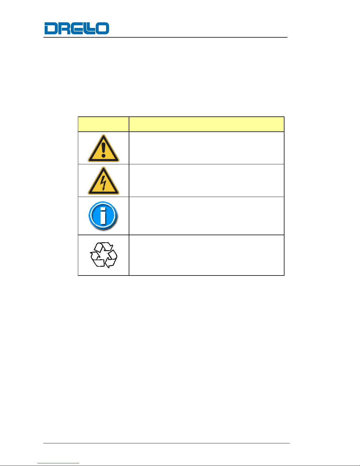
1.2 Explanation of symbols
All warnings in these operating instructions are also indicated by a
warning symbol.
The following warning symbols are used throughout these operating instructions:
Symbol Meaning
General warning
Danger of electric current
General instructions and useful suggestions on
handling
Note on observing environmen tal regula tio ns
for disposal
Page 7
General
DRELLOSCOP 1020 7
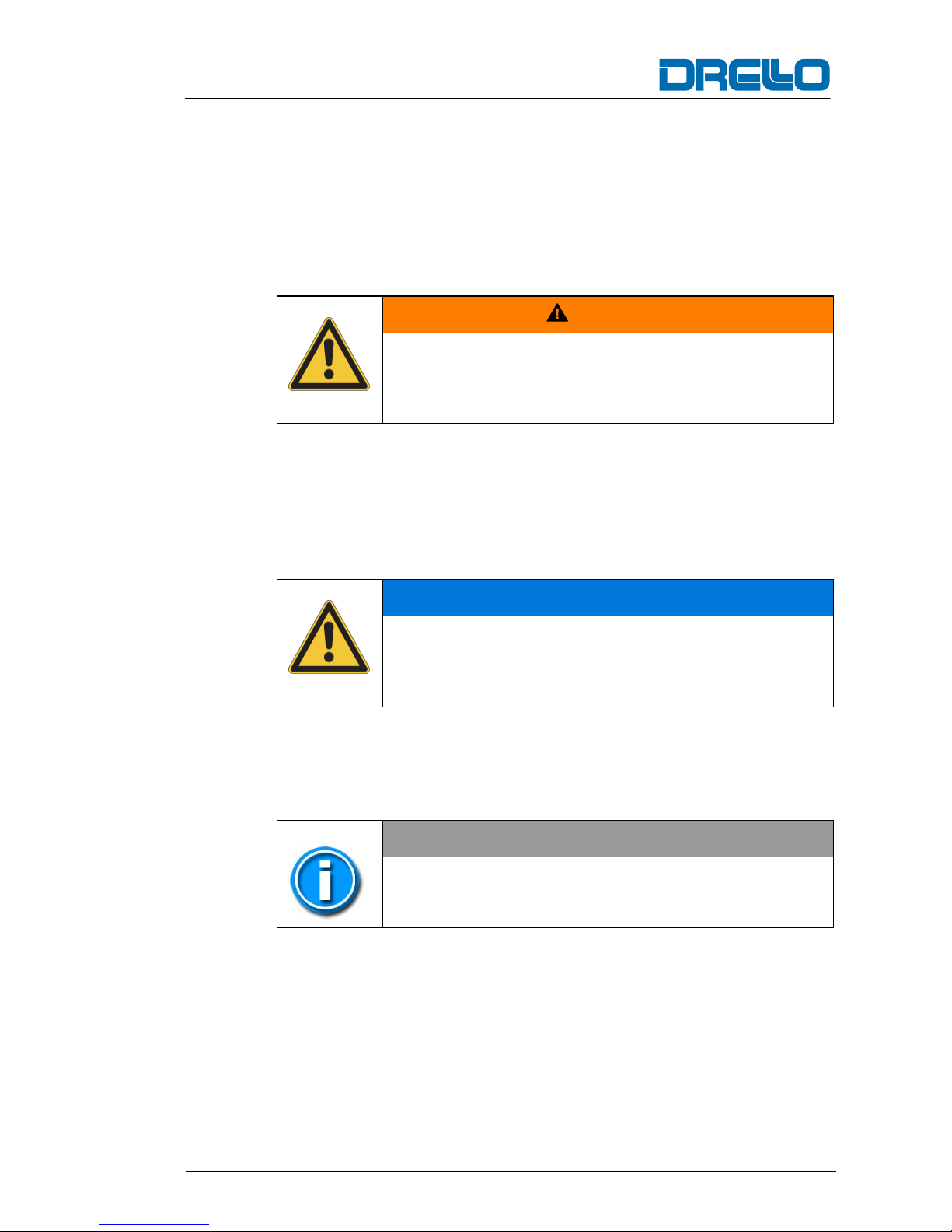
1.3 Warnings
The warnings used in these operation instructions are indicated by
signal words that are intended to indicate the extent of the danger.
The warning symbol also indicates the type of danger.
The following warning symbols are used throughout these operating instructions:
WARNING
Risk of injury!
Consequences of failure to observe...
► Instructions for avoidi ng
A warning of this category indicates a potentially dangerous situation. If the dangerous situation is not avoided, it may lead to serious
injury or even death.
Follow the instructions in this warning to avoid possible danger of
serious injury or even death.
CAUTION
Damage to property by...
Consequences of failure to observe...
► Instructions for avoidi ng
This warning level indicates potential damage to property. If the situation is not avoided, it may lead to damage to property.
Follow the instructions in this warning to avoid material damage.
NOTE
Descriptive text…
A descriptive text contains additional information that is important
for further processing or for simplifying the procedure step explained.
Page 8
General
8 DRELLOSCOP 1020
1.4 Limitation of liability
The manufacturer assumes no liability for damage and operational
faults resulting from:
■ failure to observe these operating instructions,
■ use for other than the intended purpose,
■ deployment of non-trained or insufficiently-trained staff,
■ use of non-approved equipment,
■ faulty connection,
■ previous work that is not part of the scope of supply,
■ failure to use original replacement and acce ssory parts,
■ technical modifications and changes not approv ed by DRELLO,
■ failure to perform prescribed maintenance work.
With the exception of further claims, DRELLO is liable for any errors or omissions within the framework of the warranty obligations
stated in the contract.
Claims for damage are excluded irrespective of the legal basis.
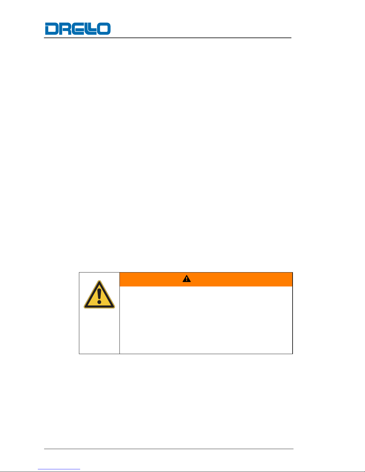
1.5 Spare parts
WARNING
Danger of injury due to wrong or faulty spare
parts!
Incorrect or faulty replacement parts can lead to
damage, malfunction or total breakdown of the
equipment as well endangering the safety.
► Use only the original spare parts of
the manufacturer.
Page 9
Safety
DRELLOSCOP 1020 9
2 Safety
2.1 General
This section provides important instructions on all safety aspects
for optimum protection of staff as well as safe and smooth operation.
WARNING
Danger from failure to observe the safety instructions!
Failure to observe the safety and handling instructions listed in these operating instructions can lead
to considerable danger.
► Always pay attention to all warnings and instruc-
tions specified here.
2.2 Responsibility of the operator
Since this device is used in the commercial sector, the operator is
subject to the legal requirements for occupational safety.
In addition to the occupational safety instructions in these operating
instructions, the current safety, accident prevention and environmental protection regulations relevant for operation of the device
must be complied with.
The operator must
■ be informed on the current industrial safety r egulation s and c on-
duct risk assessment to determine additional hazards specific to
the device that result from the special work conditions at its lo c ation. These must be implemented in the for m of in structions for
the operation of the device.
■ continually check during the entire per iod of serv ice that all oper-
ating instructions created by hi m comply with current regulations
and to modify them if necessary.
■ clearly regulate and determine the responsi bilitie s of t he staff f or
installation, operation, maintenance and c leaning
Page 10

Safety
10 DRELLOSCOP 1020
■ ensure that all persons handling the dev ice have r ead and un der-
stood these operating instructions. In addit ion, he mu st ensure
that persons are regularly trained and informed on all haz ar ds
when using the device.
■ check that staff observes the oper ating instru ctions a nd is aware
of safety and danger while w orking w ith the dev ice.
■ ensure that these operating instructions and all additional regula-
tions can be accessed by operating and ma intenanc e staff.
■ determine a person responsible for the dev ice and allow him to
reject instructions from third par ties that ar e prejud icial to safety!
■ make the necessary protective equipment av ailab le to staff.
The operator is also responsible that the device is always in perfect
condition and the following therefore applies:
■ The operator must ensure that the cleaning and mai ntenanc e in-
tervals stated in these operating instructions are adhered to.
Page 11
Safety
DRELLOSCOP 1020 11
2.3 Staff requirements
2.3.1 Staff qualifications
WARNING
Risk of injury due to insufficient qualification!
Improper use can result in considerabl e damag e to
persons or property.
► All activities shall only be performed by qualified
staff.
The following qualifications are stated in these operating instructions for various different fields of activities.
■ Instructed person
was instructed by the operator on their assigned responsibilities
and the possible dangers resulting from improper behaviour.
■ Specialist staff
is able to carry out assigned work tasks as well as recognise
and prevent possible dangers based on his/her technical training, knowledge and experience, including knowledge of applicable regulations.
Only those staff members are permitted who can be expected to reliably perform their task. Those staff members whose responsiveness is affected by substances such as medication shall not be
permitted.
Allow staff to be trained or instructed and/or persons undergoing
general training to work on the device only under the constant supervision of an experienced person!
NOTE
Observe age and occupational-specific reg ulations
at the location of the device when selecting staff.
Page 12
Safety
12 DRELLOSCOP 1020
2.3.2 Unauthorised persons
WARNING
Danger for and resulting from unauthorised
persons!
Unauthorised persons who do not fulfil the requirements are not familiar with the dangers at the work
location.
► Do not permit unauthorised persons to be in the
vicinity of the work area.
► In case of doubt, approach the persons and
instruct them to leave the work area.
► Do not continue with work while the unauthor-
ised person is in the vicinity of the work area.
2.3.3 Instruction
Staff must be regularly instructed by the operator.
NOTE
In order to keep track and protocol all instruction
sessions, participating members of staff are required to acknowledge with their signature.
Page 13

Safety
DRELLOSCOP 1020 13
2.4 Intended use
The device is portable and intended for visual che ck ing of mo v ing
work sequences. It is possible to connect an external controller via
machine impulse for example.
Any use other than previously stated is considered as improper
use.
WARNING
Danger from use for other than the intended
purpose!
Any use other than and/or going beyond the intended use of the device can lead to dangerous situations.
► Only use the device for its intended purpose.
► Pay attention to all specifications in these
operating instructio ns.
No claims of any kind will be accepted for damage resulting from
use of the appliance for other than its intended purpose. The risk
must be borne solely by the user.
2.5 Device protection
The DRELLOSCOP 1020 is protected during battery operation by
an internal self-restoring fuse, which is not replaceable. If the
DRELLOSCOP 1020 is operated via the NG-1020 mains supply,
the device is protected by the fuse of the mains supply.
Page 14
Safety
14 DRELLOSCOP 1020
2.6 Particular hazards
2.6.1 Danger from stroboscopic light flashes
WARNING
Danger from stroboscopic light flashes
In rare cases, stroboscopes can cause epileptic fits
when operated at a frequency of approx. 10 – 20 Hz.
The risk increases if the contrast between the flash
and the ambient lighting is high. Even persons who
have never experienced an epilept ic fit can be affected. Consequent injury such as falling over can
therefore not be ruled out.
► If possible, always work in normal ambient light
conditions.
► When setting the flash sequence, begin with the
highest frequency.
► Make sure that persons suffering from epilepsy
are not in the vicinity of the device during operation.
WARNING
Danger from optical illusions!
A rotating machine part appears to be stationary at
certain settings of the device. Persons who are not
informed of this effect may reach into or be caught
by the running machine, which could lead to serious
or even fatal injuries.
► Inform all persons who stand in the vicinity of
the illuminated area on the functionality of the
device and make them aware of the danger that
can result from the optical illusion.
Page 15

Technical specifications
DRELLOSCOP 1020 15
3 Technical specifications
Dimensions
Length / width 200 - 85 mm
Height / with rotary adjuster 40 - 55 mm
Weight approx. 0.5 kg
Controller
Manual controller (internal) via rotary adjuster,
120...25000 min-1 or
2...416.6 sec-1
fast finder function by multiplica-
tion/division of the set flash sequence
External controller via rectangular pulse 10...24 V
60…199999 min
-1
or 1…3333 sec-1
display up to 99999 min-1 (1666.6 Hz)
or 3333.3 sec-1
smooth real-
time image shifting 0...360°
and slow-motion function, automatic input
frequency division from 416.66 sec-1
Flash length control automatic, depending on the
flash sequence or manual by rotary
adjuster, setting range 1...250 μs
Maximum flash sequence 416.66 sec-1 or 25000 min-1
Measured value display 5-digit 7-segment display,
number height 7.6 mm
Electrics
Mains supply 3 x 1.2 V NiMH rechargeable batteries
(AA),
fast charging capability
Plug-in mains supply 5 VDC
Power consumption 400 mA @ 5 VDC
Reverse polarity protection yes
Operating time (battery) approx. 4 hours at full load
(depending on battery type, 2850 mAh)
Operating time (plug-in mains
supply)
Continuous operation
Page 16

Technical specifications
16 DRELLOSCOP 1020
Ambient conditions
Ambient temperature range 0 … +4 5 °C
Storage temperature range -20 … +60 °C
Degree of protection IP50
Illumination
LED High-performance LED, white radiating
combined with highly-efficient optics
Colour temperature 6500 K
Illumination Ø 150 mm @ 300 mm object gap
Illumination strength 3500 lx @ 200mm object gap; meas-
ured at 50 Hz and 50 µs flash length
CE declaration of conformity printed version on request
NOTE
Battery operation
Following detection of undervoltage during battery
operation (display flashes), the device can be
operated for approx. 15 minutes.
Page 17

Description
DRELLOSCOP 1020 17
4 Description
4.1 Description of functions
The DRELLOSCOP 1020 is a portable LED hand-held stroboscope
for use in a harsh industrial environment.
Switching the appliance ON/OFF
The device is switched on or off by pressing the ON/OFF button.
A display test is performed after switching on. All display elements
light up for approx. 4-5 seconds and subsequently switch to the
basic setting (LED sec
-1
lights up, display value is 50,000). P ress-
ing the "ON/OFF" button again, switches off the device.
Internal controller (hereinafter referred to as manual controller)
Flash sequence 2.00 sec-1 ...416.67 sec-1 / 120 min-1....25000 min-1.
Setting takes place via the rotary adjuster.
Turn clockwise → flash sequence increases
Turn anticlockwise → flash sequence decreases
Fast finder function
Pressing the "Double" button mult ipl ies the curr ent flas h seq uenc e
by a factor of 2. Pressing the "Halving" button divides the current
flash sequence by two. Exceeding the lower or higher flash sequence limit (2Hz / 416.67Hz) is not possible and in this case, multiplication or division by 2 is not performed. This function allows
convenient detection of the true flash sequence with respect to the
object motion sequence.
Explanation
If an intermittent moving object seems to be standing still, the flash
sequence corresponds to the motion sequence or the ratio is an integer number. However, the highest flash sequence possible
should be set in order to produce a simple stati onary image . When
this has been achieved, the flash sequence is multiplied by a factor
of 2 by pressing the "Double" button. If a doubled stationary image
is then produced, the previously set flash sequence is correct. If
however, a single stationary image is produced, the set flash sequence was too low. Repeated doubling of the flash sequence
helps to determine the correct motion sequence. If this is higher
than the flash sequence range of the stroboscope allows, the true
motion sequence can be determined using a following method:
Page 18

Description
18 DRELLOSCOP 1020
Starting with the highest flash sequence, the first two values are
determined by reducing them, which then produces simple stationary images of the object. This then results in the true motion sequence
True motion sequence f
x
[Hz] = n ∙ f1 [Hz]
with
[ ]
[ ] [ ]
HzfHzf
Hzf
n
21
2
−
=
Example:
Beginning with the highest flash sequence (416.66Hz), the flash
sequence is reduced until a simple stationary image results. The
flash sequence is named f
1
.
The flash sequence is then reduced further until another simple stationary image can be seen. The motion sequence is named f
2
.
To determine the "n" factor, the determined values f
1
and f2 are in-
serted into the corresponding formula. The true motion sequence f
x
cannot be determined using the formula (fx = n ∙ f1). If rotating objects are being examined, rotation-symmetric al str u ct ur e s su ch as
spoke wheels must be marked to rule out ambiguity due to symmetry.
External controller
Pressing the "External" button ( cogw heel sy mbo l) other w ise name d
Extended External Control activates the "external co ntr ol " fun ctio n.
The frequency of the impulse sequence supplied then appears in
the display. The flash sequence is synchronised to the incoming
control impulses and therefore creates the impression that the object is stationary even with heavily fluctuating movement for example. If no control signal is supplied to the "external input", the value
0.0 appears in the display after approx. 2 seconds.
If the input frequency is greater than 416.67 sec
-1
, the flash sequence is automatically split to a permissible flash sequence value.
The displayed value corresponds to the original input frequency.
Note that a frequency input greater than 1.6666 KHz (99999 min
-1
)
cannot be displayed in min-1. Input frequencies greater than
3.33 kHz are not permit ted, t h e error cod e (Err 1) is displayed.
Flash sequences that are smaller than 1 Hz are not permissible
and are indicated by an error code (Err 2). However, flash triggering still takes place irrespective of this error message.
Page 19

Description
DRELLOSCOP 1020 19
Menu control
Additional function expansions or display values can be set via the
menu control.
Menu functions for manual control:
■ Display value in sec
-1
■ Display value in min
-1
■ Flash duration display or setting
Also with extended control
■ Setting of the image position and display of the pha se angle i n
degrees
■ Setting of the slow-motion funct ion und disp lay of the slow-motion
angle in degrees
For further information, refer to the "Menu structure" section
NOTE
The menu level "Display value selection or functions" is closed after pressing the "Menu" button
directly afterwards. The original setting remains
unchanged. For all other levels, the selected menu
functions are accepted.
Generally, all settings in the menu can be confir me d
by pressing the rotary adjuster.
Sleep function
If no settings to the device are made by the user, it is switched to
sleep mode after approx. 16 minutes. This reduces the intensity of
the display field and the keyboard considerably and the flash function is switched off. Pressing a button or the rotary adjuster switches the device back to the operating mode and the flash function on.
Page 20

Description
20 DRELLOSCOP 1020
4.2 Device overview
1 Display Displays the current value of the
selected function.
2 Display for min
-1
Display of flashes per minute. The LED
lights up when the function is selected.
3 "Menu" button Menu control selection. The LED lights
up when the function is selected.
1
2
3
4
5
6
10
9
8
7
Page 21

Description
DRELLOSCOP 1020 21
4 Rotary adjuster The rotary adjuster is used to switch the
flash mode on and off and for confirming
the menu functions.
Turning clockwise or anticlockwise, settings are made for the flash sequence
during manual control, image position,
slow-motion angle, flash duration, menu
selection and the "sec
-1
" or "min-1" dis-
play.
5 Double button The current flash sequen ce is multipl ied
by a factor of 2. This is for fast retrieval
of the true object frequency.
6 ON/OFF button Switches the device ON/OFF.
7 9-pole device
plug
Connection for the NG-1020 mains
adapter and supply of the control signals
for the "external control" mode
8 Halving button The current flash sequence is divided by
a factor of 2. This is for fast retrieval of
the true object frequency if the stationary
image is displayed repeatedly.
9 External button Selection of external control. The LED
lights up when the function is selected.
10 Display for sec-1 Displays number of flashes per second.
The LED lights up when the function is
selected.
Page 22

Description
22 DRELLOSCOP 1020
4.2.1 Front view
1 LED with lens High-performance LED with integrated
lens.
4.2.2 View from underneath
1 Lid fixing Thread for removing the fixing screws of
the battery compartment lid.
2 Battery compart-
ment
Battery compartment for accommodating
3 rechargeable 1.2V AA /HR6-size batteries (see scope of delivery)
1
1 2 1
+
+
Page 23
Description
DRELLOSCOP 1020 23
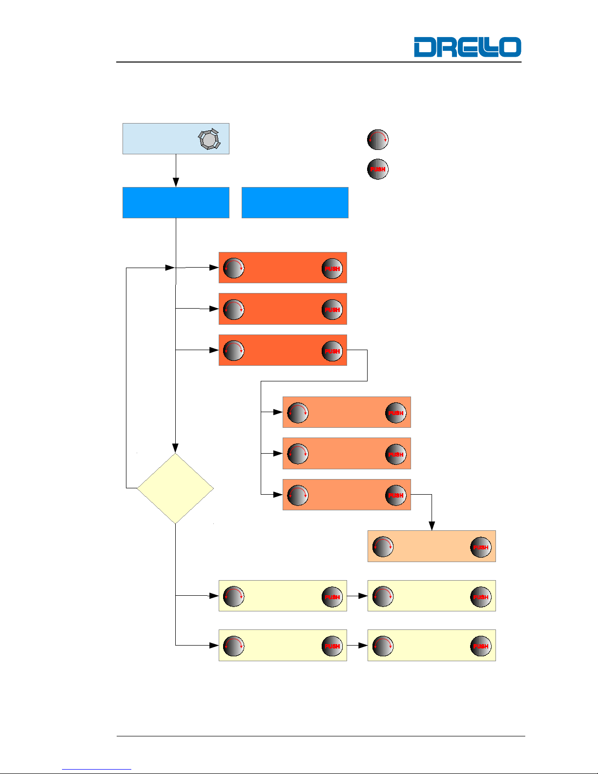
4.3 Menu structure
Menu button
M
Display secˉ1
Display min
ˉ1
Function dur.
POSITION
SL-MOTION
Display dur
Autom. dur. A
Manuel dur. F
Manuel dur. F
Press once for
selection
Press twice for
break-off
External
function
Yes
No
Selection via adjustor
Confirm entry by pressing
the button and chose
function
Rotary adjustor
Setting
position
Setting
slow motion
Page 24

Description
24 DRELLOSCOP 1020
4.4 Type plate
The type plate is located on the underneath of the device. It includes
the following information:
■ Device designation
■ Serial number
■ Connection values
■ Options
Page 25

Transport, assembly and connection
DRELLOSCOP 1020 25
5 Transport, assembly and connection
5.1 Scope of supply
The DRELLOSCOP 1020 system is supplied with the following
components depending on the system number:
DRELLOSCOP 1020 system number: 1.1020.00001
No.
Designation
Article number
1 DRELLOSCOP 1020
1.1020.60001
1 NG-1020 plug-in mains supply
1.1020.20001
3 NiMH 1.2V / 2100mAh HR6 (AA) recharge-
able battery
23.02.022
1 TK-1020-01 plastic transport case
39.1020.001
DRELLOSCOP 1020 operating manual, English
1.1020.2B001e
DRELLOSCOP 1020 system number: 1.1020.00002
No.
Designation
Article number
1 DRELLOSCOP 1020
1.1020.60001
1 LA 1020B charging device (Basic 4 plus)
59.1020.20001
6 NiMH 1.2V / 2100mAh HR6 (AA) recharge-
able battery
23.02.022
1 TK-1020-02 plastic transport case
39.1020.002
DRELLOSCOP 1020 operating manual, English
1.1020.2B001e
DRELLOSCOP 1020 system number: 1.1020.00003
No.
Designation
Article number
1 DRELLOSCOP 1020
1.1020.60001
1 LA 1020B charging device (Basic 4 plus)
59.1020.20001
3 NiMH 1.2V / 2100mAh HR6 (AA) recharge-
able battery
23.02.022
1 NG-1020 plug-in mains supply
1.1020.20001
1 TK-1020-02 plastic transport case
39.1020.002
DRELLOSCOP 1020 operating manual, English
1.1020.2B001e
Page 26

Transport, assembly and connection
26 DRELLOSCOP 1020
DRELLOSCOP 1020 system number: 1.1020.00004
No.
Designation
Article number
1 DRELLOSCOP 1020
1.1020.60001
1 LA 1020US charging device (Ultra Fast)
59.1020.20003
6 NiMH 1.2V / 2850mAh HR6 (AA) recharge-
able battery
23.02.022
1 TK-1020-02 plastic transport case
39.1020.002
DRELLOSCOP 1020 operating manual, English
1.1020.2B001e
DRELLOSCOP 1020 system number: 1.1020.00005
No.
Designation
Article number
1 DRELLOSCOP 1020
1.1020.60001
1 LA 1020US charging device (Ultra Fast)
59.1020.20003
3 NiMH 1.2V / 2850mAh HR6 (AA) recharge-
able battery
23.02.023
1 NG-1020 plug-in mains supply
1.1020.20001
1 TK-1020-02 plastic transport case
39.1020.002
DRELLOSCOP 1020 operating manual, English
1.1020.2B001e
NOTE
Check the entire delivery according to the delivery
note for completeness. We also refer you to our sales
and delivery conditions.
Measures in the event of transport damage
Report damage due to defective packaging or damage incurred
during transit to the haulage contractor, insurer and factory immediately after delivery .
Take steps to reduce existing damage and prevent any further
damage.
Page 27

Transport, assembly and connection
DRELLOSCOP 1020 27
5.2 Available accessories
The following accessories are av ailab le for the device:
No. Designation Article number
1 Sensors for the external controller
on request
5.3 Unpacking
Remove all packaging materials and protective foils from the product and the accessories before using it for the first time.
NOTE
► Do not remove the rating plate or any warning
signs on the appliance.
► If possible, keep the original packaging during the
guarantee period in order to be able to pack the
appliance properly in the event of a guarantee
claim. Transport damage will invalidate the guarantee.
NOTE
The packaging materials used can be recy cled. When
no longer required, dispose of the packaging materials according to local environmental regulations.
Page 28

Transport, assembly and connection
28 DRELLOSCOP 1020
5.4 Storage
The following regulations apply for storage:
■ Store at a dry place. Maximum relativ e humidity : 80%, non-
condensing
■ Protect from direct sunlight. Keep storage temp er ature
between -20 … +60 °C.
■ Store at a dust-free location.
■ Avoid mechanical vibration and damages.
NOTE
After use, store the device in the transport case supplied and also in the original packaging if possible.
CAUTION
Risk of damage to the device due to leaking batteries!
When storing for longer periods of time, ´the rechargeable batteries can leak and damage the device.
► Before storing for longer periods of time, remove
the batteries and store them in the battery compartments proved in the transport case.
Page 29

Transport, assembly and connection
DRELLOSCOP 1020 29
5.5 Requirements for the place of use
■ At the place of use, the device may not be subject to extreme
temperatures or humidity. Comply w ith the specificat ions for ambient conditions specified in the t echnical data.
■ Avoid setting up at locations with direct sunl ight .
■ Avoid strong ambient lighting at the place of u se in order to
achieve a good contrast.
■ Do not subject the device to vibration or knoc ks.
5.6 Mains operation
When using the NG-1020 plug-in mains supply (depending on the
scope of supply), battery operation is switched off automatically.
Carry out the electrical connection of the device as follows:
Insert the 9-pole cable socket of the connectin g cabl e
for the NG-1020 plug-in mains supply into the 9-pole device
connection plug of the DRELLOSCOP 1020 and secure it
against loosening by means of the locking screws.
Insert the plug of the NG-1020 plug-in mains supply into the
mains socket.
CAUTION
Risk of damage to the device due to incorrect pin
assignment!
Incorrect pin assignment of the connecting cable can
lead to destruction of the electrical components in
the device.
► Only use the NG-1020 plug-in mains supply from
the manufacturer.
Page 30

Transport, assembly and connection
30 DRELLOSCOP 1020
5.7 Connecting an external controller
If the device is to be connected to an external controller, the connections on the 9-pole plug must be undertaken by a qualified specialist electrician.
Pin assignment
The pin assignment of the connecting plug is depicted as follows:
Numbering of the device connection plug (top
view)
Pin Signal Direction Level
1 not assigned
2 not assigned
3 Supply voltage (+) Input 5 VDC
4 not assigned
5 Trigger impulse (0 V) Input 0 V trigger
6
Trigger impulse
(+)___----___ 10...24 VS
7 not assigned
8 Supply voltage (-) Input 0 V
9 Supply voltage (-) Input 0 V
Page 31

Operation
DRELLOSCOP 1020 31
6 Operation
6.1 Switching the device ON/OFF
The device is switched on or off by pressing the ON/OFF button.
After switching on, a display test is performed. All display elements
light up for approx. 4-5 seconds and subsequently switch to the
basic setting (LED sec
-1
lights up, display value 50,000). The de-
vice is subsequently ready for operation.
The device is switched off by pressing the butto n again .
6.2 Operating
6.2.1 Selecting the operating mode
The device can be operated in two modes:
Manual controller
This function is active when the LED of the "EXTERN" button is not
lit up. If the LED of the "EXTERN" button lights up, press the "EXTERN" button to activate manual control.
In manual control, the flash sequence is set with the rotary adjuster.
The object to be controlled should speed up to its target speed
in order to adjust the flash sequence.
Press the rotary adjuster to switch on the flash trigger.
Set the flash sequence via the rotary adjuster so that a stationary image is seen by the observer.
The flash sequence speed is increased by turning the rotary adjuster clockwise and decreased by turning anticlockwise.
If multiple images the object are seen, press the "Halving" button. Repeat this procedure until a single stationary image of the
object is achieved.
Page 32

Operation
32 DRELLOSCOP 1020
External controller
This function is available when the device is connected to a pulse
generator, from which it obtains control impulses. This type of flash
sequence control also generates the desired stationary image even
if the machine speed changes.
Press the "EXTERNAL" button . T he ex ternal control ler is act ivated when the LED of the button lights up.
The frequency of the supplied pulse sequence appears in the
display. If no control signal is suppl ied to the "ex ternal inp ut ",
the value 0.0 appears in the display after approx. 2 seconds.
NOTE
► If the input frequency is greater than 416.67 sec-1,
the flash sequence is split down to a permissi ble
flash sequence value automatically. The value
displayed corresponds to the original input frequency.
► An input frequency greater than 1.666 KHz can-
not be displayed in min
-1
.
► Input frequencies greater than 3.333 kHz are not
permissible and are indicated by an error code
"Err 1".
► Flash sequences that are smaller than 1 Hz are
not permissible and are indicated by an error
code "Err 2". However, flash triggering still takes
place irrespective of this error message.
NOTE
If the menu button is pressed, the measured value
can be depicted also for input signals smaller than
1Hz or greater than 3.333Khz in sec
-1
or up to
1.666KHz in min
-1
respectively.
Page 33

Operation
DRELLOSCOP 1020 33
6.3 Further setting options for flash operation
(manual control)
6.3.1 Setting the flash sequence display
Press the "Menu" button. The LED lights up when the function
is selected.
Turn the rotary adjuster until the lights up with "Display min-1" or
"Display sec
-1
".
If the desired display (min-1 or sec-1) was selected, press the rotary adjuster to confirm selection.
NOTE
The menu is closed automatically and all settings are
stored.
6.3.2 Displaying the current flash duration
Press the "Menu" button. The LED lights up when the function
is selected.
Turn the rotary adjuster until the "dur." function is displayed.
Press the rotary indicator.
The current flash duration is displayed in [μs]. Either "dA" for
Duration-Automatic-Mode or "dF" for Duration-Fix-Mode is in
front of the number.
If the setting is to be changed, select the corresponding function
(refer to following section).
Press the rotary adjuster to either set the flash duration
(Fix-Mode) or to exit the function. The changed setting is saved.
NOTE
To exit the function, press the Menu button again.
The menu is closed.
Page 34

Operation
34 DRELLOSCOP 1020
6.3.3 Setting the "Duration-Auto-Modus" variable flash duration
The flash duration is adjusted automatically to the flash sequence
with this function. Automatic adjustment gives the impression of a
constant brightness irrespective of the flash sequence.
NOTE
Use this function if a continual impression of brightness is desired irrespective of the flash sequence
used.
Press the "Menu" button. The LED lights up when the function
is selected.
Turn the rotary adjuster until "dur." is displayed.
Press the rotary indicator.
The current flash duration is displayed in [μs]. Either "dA" for
Duration-Automatic-Mode or "dF" for Duration-Fix-Mode is in
front of the number.
Turn the rotary adjuster until "dA" is displayed.
Press the rotary indicator. The device is in automatic mode and
the current flash duration is displayed in [μs].
Press the "Menu" or rotary adjuster button. The menu control is
closed and the settings saved.
Page 35

Operation
DRELLOSCOP 1020 35
6.3.4 Setting the flash duration "Duration-Fix-Modus"
This function allows the flash duration to be set to a fixed value irrespective of the flash sequence. Adjustment of the fla sh sequen ce
makes it possible to eliminate possible motion blur while depicting
the moving object.
NOTE
Use this function if significant motion blur is detected
or the brightness needs to be reduced.
Press the "Menu" button. The LED lights up when the function
is selected.
Turn the rotary adjuster until "dur." is displayed.
Press the rotary indicator.
The current flash duration is displayed in [μs]. Either "dA" for
Duration-Automatic-Mode or "dF" for Duration-Fix-Mode is in
front of the number.
Turn the rotary adjuster until "dur F" is displayed.
Press the rotary indicator. The device is in fix mode.
Set the flash duration by turning the rotary adjuster.
Press the "Menu" or rotary adjuster button. The menu control is
closed and the settings saved.
NOTE
Manual setting of the flash duration may not exceed
the maximum permissible flash duration for the respective flash sequence.
An additional protective function (overload protection)
reduces the manually set flash duration automatically
when this reaches a non-permissible value as a result of a change in the flash sequence.
Page 36

Operation
36 DRELLOSCOP 1020
6.4 Further setting options for flash operation
(external control)
6.4.1 Image shift (PHASE)
The object to be controlled can be "shifted" into the optimum
position. The flash moment is changed electro nic al ly that another
image position of the object can be viewed.
NOTE
This function is useful when the object does not need
to be completely illuminated.
NOTE
The "image shift" function is deactivated in the "external controller" mode after switching on the device.
The "PHASE" function must called first to enable it.
Switching off the function is only possible if either the
"slow-motion" functi on is selec ted or the dev ice is
briefly switched off and on again.
Press the "Menu" button. The LED lights up when the function
is selected.
Turn the rotary adjuster until "PHASE" is displayed.
Press the rotary adjuster to activate the image shift setting and
to read the current "phase angle" (image position) with respect
to the input signal.
Turn the rotary adjuster to set the desired image position.
Press the "Menu" or rotary adjuster button. The menu control is
closed and the settings saved.
NOTE
After closing the "PHASE" menu functi on, the set
image position remains and can be further modified
with the rotary adjuster. However, the phase angle is
no longer displayed.
Page 37

Operation
DRELLOSCOP 1020 37
6.4.2 Setting the slow-motion function
With external control of the flash sequence a continual, apparent
image shift can be set. The eye perceives this as a sequence in
slow motion.
NOTE
The "scrolling" is deactivated after switching on the
device in "external control" operating mode. The
"SLO" function must be called first to enable it.
Switching the function on/off is only possible when
either the "PHASE" function (image shift) is selected
or the device is switched off briefly and then switched
on again.
Press the "Menu" button. The LED lights up when the function
is selected.
Turn the rotary adjuster until "SLO" is displayed.
Press the rotary adjuster to activate the slow-motion function
and to read the current "slow-motion angle" with respect to the
input signal.
Set the slow-motion speed by turning the rotary adjuster
Press the "Menu" or rotary adjuster button. The menu control is
closed and the settings saved.
NOTE
The apparent slow-motion effect (scrolling) remains
after switching off this function and can be further
modified with the rotary adjuster. However, the "slowmotion angle" is no longer displayed.
NOTE
The "slow-motion angle" serv es as a setting aid.
Once set, it is adjusts itself automatically to the
changing object speed. This automatic adjustment
keeps the apparent circulation speed constant irrespective of the object speed.
Page 38

Maintenance and repair
38 DRELLOSCOP 1020
7 M aint en an ce and rep air
7.1 Maintenance
No maintenance work on the device is necessary. Only the rechargeable batteries used must be charged as required with the
charging station supplied.
NOTE
If the DRELLOSCOP 1020 is not to be used for a
longer period of time, remove the batteries from the
device and insert them into the battery compartment
provided in the transport case.
7.2 Changing the batteries
Switch off the device.
Unscrew both screws of the battery lid and remove it.
Remove any batteries.
Insert the loaded batteries according to polarity into the battery
compartment, replace the lid and the screws.
Charging the batteries
NOTE
When the battery voltage is too low, the indicator in
the display starts flashing. If the voltage sinks further,
flash operation switches off automatically and "dc Lo"
appears in the display. The batteries must be replaced.
The device switches off automatic ally w ithin 30 seconds.
NOTE
If the DRELLOSCOP 1020 is not to be used for a
longer period of time, remove the batteries from the
device and insert them into the battery compartment
provided in the transport case.
Page 39

Maintenance and rep ai r
DRELLOSCOP 1020 39
7.3 Cleaning
Clean the lens (light emitting surface) with a damp cloth as required.
If dirty, clean the housing of the device with a slightly damp, lintfree cloth. Do not use cleaners containing solvents.
7.4 Troubleshooting
Fault Cause Remedy
No display Batteries discharged. Recharge batteries
No voltage supply. Check
connecting cable.
Stroboscope not
switched on.
Switch on
stroboscope.
Display is flashing
Battery voltage in
lower permitted range.
Change the batteries
immediately.
Display is flashing, "dc Lo" is
displayed and
operation not
possible.
Battery voltage too
low.
Replace batteries
immediately.
The device does
not flash with
manual controller.
"External controller"
operating mode is activated without a trigger impulse.
Switch over to "manual controller" operating mode.
The device does
not flash with external controller.
There is no trigger
impulse.
Check external impulse generator
"Err 1" display Input frequency above
3.33 kHz.
Reduce input frequency.
"Err 2" display Input frequency below
1.00 Hz.
Increase input frequency.
Page 40

Maintenance and rep ai r
40 DRELLOSCOP 1020
7.5 Repairs
Do not perform repairs on the device yourself. Contact customer
service at DRELLO. Improper work can result in personal injuries,
damage to property or damage to the device itself.
If repairs must be performed, please cont act:
DRELLO Ing. Paul Drewell GmbH & Co. KG
Customer service
Andreas-Bornes-Strasse 46
D-41179 Mönchengladbach
Telephone: +49 - (0)2161 - 909 - 6
Telefax: +49 - (0)2161 - 909 - 700
Email: service@drello.de
Internet: www.drello.de
7.6 Disposal
This product may not be disposed of in the domestic refuse within
the European Union.
Dispose of the device in accordance with the EC Directive Waste
Electrical and Electronic Equipment 2002/96/EC. Questions on disposal can be answered by the responsible local authority.
 Loading...