

Page 1
DREHMO
C-matic
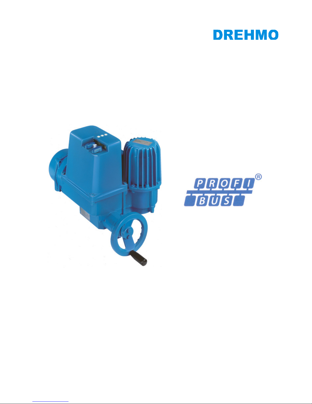
Electrical actuator with integral controls
Complementary operating manual for drives with
PROFIBUS DPV0/DPV1 interface
Operating manual T.-Nr. 186619
Version 1.6
Date: June, 23th 2014
INFORMATION
This operating manual has to be used in conjunction
with the operating manual for actuators (from version 1.15)!
This manual must be kept for future use.
Page 2

Document history
File revision
Date Changes
0 2009-04-15 First release (T-OF)
1 2009-05-12 Review STE/WER
2 2010-03-08 S6.1 for Line redundancy described. Described additional acyclic parameters for phase
sequence detection. (T-OF)
3 2011-04-02 Added chapter GSD Files.
Updated description for FW-Download using Matic C Operator. (T-OF)
4 2011-03-28 Titel DPV1 replaced by DPV0/DPV1 (T-Ste)
5 2013-10-30 Description of the additional conventional I/O interface (parallel interface) (EE-ScMa)
6 2014-06-23 Intermediate position 1 and 2 in PPO1 and PPO2, TR11, DIM-10.4 (EE ScMa)
Contact
Service DREHMO GmbH
Tel.: +49 2762 9850-206
Fax: +49 2762 9850-205
E-Mail: [email protected]
Page 3

DREHMO - MaticC Profibus DPV0/DPV1 Page 3 of 28
Complementary operating manual
Table of contents
1 Warnings and notes ................................................................. 4
1.1 Standards / directives ....................................................................................................... 4
1.2 Commissioning (Electrical connection) ......................................................................... 4
1.3 Maintenance ...................................................................................................................... 4
1.4 Warnings and notes .......................................................................................................... 4
2 Structure of the Profibus interface board .............................. 6
3 Electrical connection ............................................................... 7
3.1 Mains connection (Standard) .......................................................................................... 7
3.2 Bus connection (Standard) .............................................................................................. 7
3.3 Bus cable ............................................................................................................................ 8
3.4 Shield connection ............................................................................................................ 10
3.5 Bus termination ............................................................................................................... 10
3.6 Additional conventional I/O interface (parallel interface) .......................................... 11
4 Switches / LED’s of the interface board ............................... 12
4.1 Location of the components on the interface board .................................................. 12
4.2 Jumper .............................................................................................................................. 12
4.3 DIL-Switches .................................................................................................................... 13
4.3.1 Profibus Address HI / LO ........................................................................................ 13
4.3.2 DIL Switch S4 ........................................................................................................... 14
4.3.3 DIL Switch S6 ........................................................................................................... 14
4.4 Diagnosis LED’s .............................................................................................................. 15
4.4.1 LED 1V8, 3V3 und 5V1 .......................................................................................... 15
4.4.2 LED BL ...................................................................................................................... 15
4.4.3 LED H16 DIAG ......................................................................................................... 15
4.4.4 LED H13/H23 (Yellow) ............................................................................................ 16
4.4.5 LED H14/H24 Profibus physically state (Green) ................................................ 16
4.4.6 LED H15/H25 Profibus protocol state (Green) ................................................... 17
4.4.7 TEST connector ....................................................................................................... 17
5 Profibus Interface ................................................................... 17
5.1 GSD-Files ......................................................................................................................... 17
5.2 Set parameter telegram ................................................................................................. 18
5.2.1 Standard parameter (7 Bytes) ............................................................................... 18
5.2.2 User specific parameters (UsrPrm data) ............................................................. 18
5.3 Process images ............................................................................................................... 19
5.3.1 PPO1: (Default) ........................................................................................................ 19
5.3.2 PPO2: (Matic C compatible) .................................................................................. 21
5.4 Acyclic data ...................................................................................................................... 22
6 System functions .................................................................... 23
6.1 Diagnostics....................................................................................................................... 23
6.2 Firmware download ........................................................................................................ 23
6.2.1 Required items ......................................................................................................... 23
6.2.2 Step by step description ......................................................................................... 23
Page 4
DREHMO - MaticC Profibus DPV0/DPV1 Page 4 of 28
Complementary operating manual
1 Warnings and notes
1.1 Standards / directives
DREHMO products are designed and manufactured in compliance with recognised standards and
directives. This is certified in a declaration of incorporation and a declaration of conformity.
The end user or the contractor must ensure that all requirements with respect to assembly,
electrical connection, and commissioning at the place of installation are met.
They include among others:
• Applicable configuration directives for fieldbus applications.
• National regulations, laws, and prescriptions.
1.2 Commissioning (Electrical connection)
During operation of electrical devices it is unavoidable that certain parts carry dangerous voltages.
All personnel working with this device must be familiar with the safety and warning instructions in
this manual and observe the instructions given. Safety instructions and warning signs on the
device must be observed to avoid personal injury or property damage.
1.3 Maintenance
Maintenance directives have to be carefully attended. Otherwise a safe operation of the actuator
or control unit can’t be assured.
1.4 Warnings and notes
Read these instructions carefully before installation and commissioning. Failure to follow them
may lead to personal injury or to material damage.
The following signs draw special attention to safety-relevant procedures in these operation
instructions:
This symbol signifies „additional information“.
Failure to observe may lead to damage occurring.
This symbol signifies „attention“.
Failure to observe may result in damage and personal injury.
This symbol signifies „warning!“.
Failure to observe may result in damage and severe personal injury.
Page 5

DREHMO - MaticC Profibus DPV0/DPV1 Page 5 of 28
Complementary operating manual
This symbol signifies „ESD hazardous device!“.
Failure to observe may result in damage of the electronic assembly.
Handling of PCBs requires basic protection against damage through electrostatic
discharge – ESD.
Before handling of PCBs discharge yourself with suitable action, for example
touching an earthed part with connection to the device.
PCBs should be touched only at the side or at metallised mounting parts. Avoid
direct contact to plug contacts and electronic parts on the PCB.
The PCB must not be placed on bare metal surfaces or potentially charged surfaces.
In case of doubt use a capable ESD pad.
Transportation of single PCBs has to be done with ESD suitable packaging to avoid
ESD damages.
Page 6
DREHMO - MaticC Profibus DPV0/DPV1 Page 6 of 28
Complementary operating manual
2 Structure of the Profibus interface board
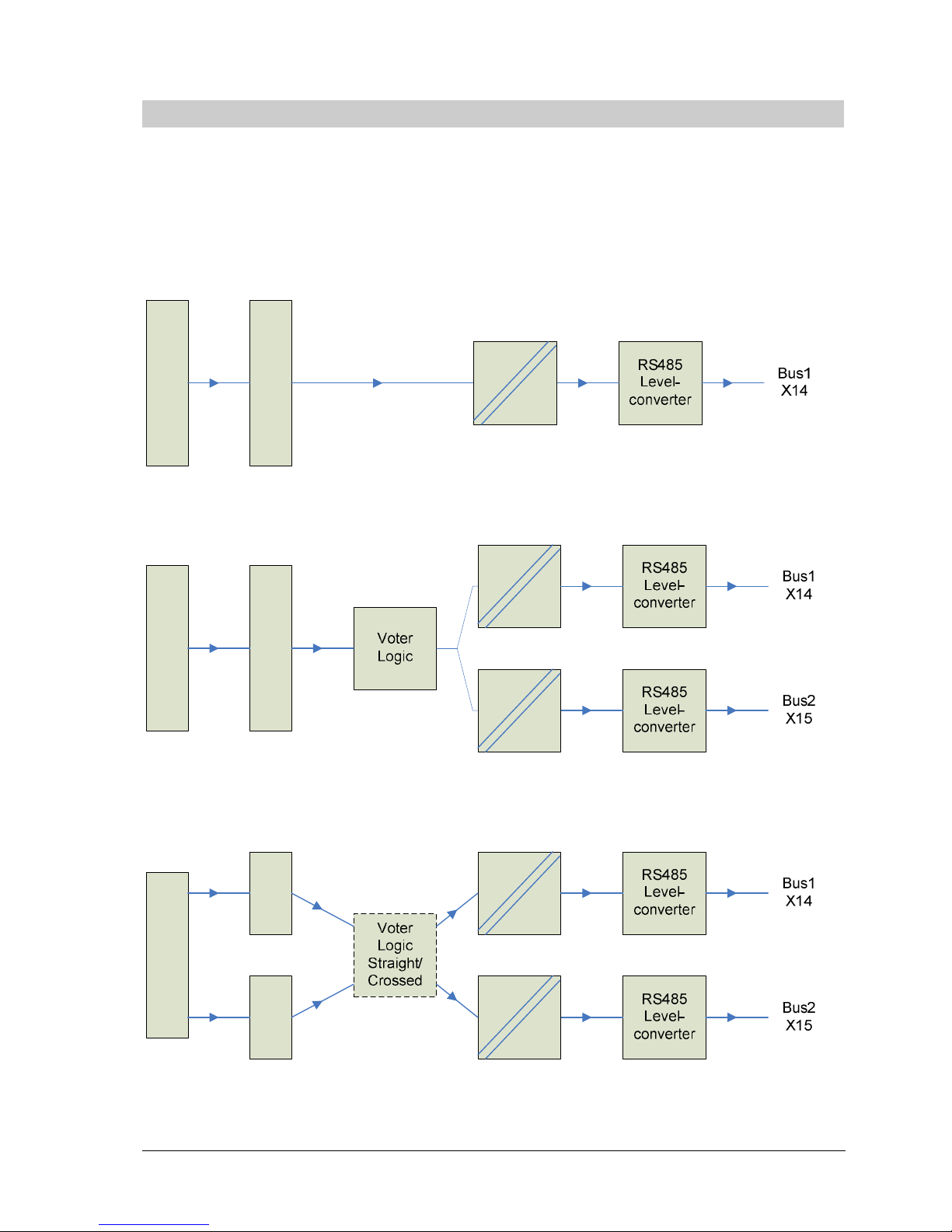
There are three different kinds of interface boards available. Depending on the desired type of
usage (Single line, Line redundant, Master/Slave redundant) the interface board is equipped with
different components.
The block diagrams are shown in the following:
Single ASIC Interface with 1-channel physical media access:
Controller
Profibus ASIC
Single ASIC Interface with 2-channel physical media access and voter logic:
Controller
Profibus ASIC
Dual ASIC Interface with 2-channel master/slave redundant physical media access and
voter logic:
Controller
Profibus
ASIC
Profibus
ASIC
Page 7
DREHMO - MaticC Profibus DPV0/DPV1 Page 7 of 28
Complementary operating manual
3 Electrical connection
3.1 Mains connection (Standard)
Work on electrical equipment and electrical installation work on actuators must be
carried out by electricians or under supervision by fully qualified engineers, in
accordance with the valid electrical regulations.
Wiring should be carried out according to the enclosed wiring diagram. All control
cables shall be shielded to guarantee the electromagnetic compatibility of the
actuator. The main power cable need not be shielded.
The overcurrent protection of the actuator has to be installed inside the power
network. For rated values, see design data.
Pay special attention to the grounding of the actuator (refer to wiring diagram). Electrical
protection is not obtained until all covers are closed.
3.2 Bus connection (Standard)
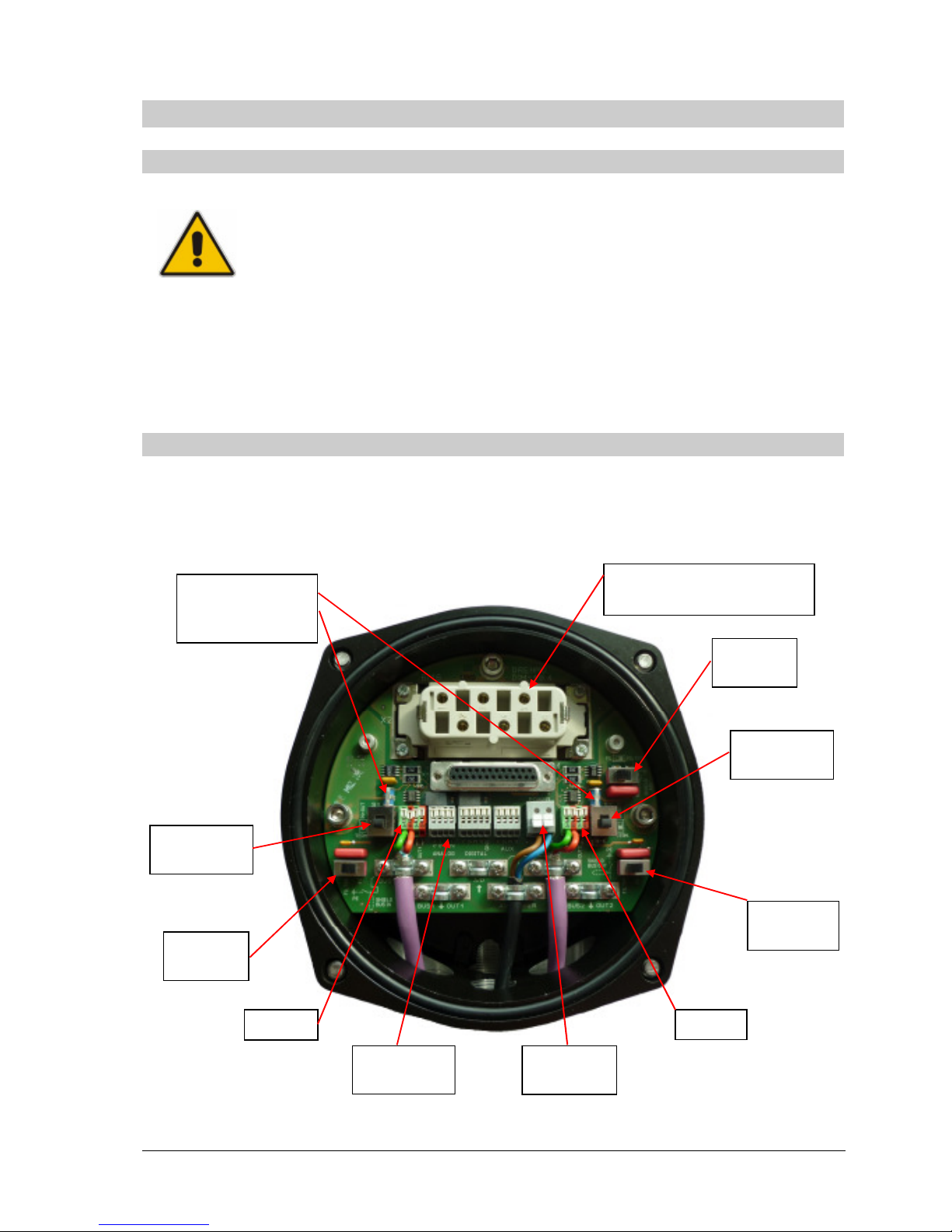
Wiring is carried out according the wiring diagram supplied with the actuator. Locations of the
connection terminals and switches are shown in the following picture. The picture shows the
version for the redundant bus connection with overvoltage protection. Depending on the
configuration it is possible, that the components for BUS 2, the optional inputs or the overvoltage
protection do not exist.
Additionally to the electrical connection enabling/disabling the Profibus termination and the
grounding of the shield is done on the connection board.
BUS 1
BUS 2
Mains supply connector
(connection on backside)
Shield
A/D
Shield
Bus OUT
Shield
Bus IN
Terminator
Bus 1
Terminator
Bus 2
Optional
A/D
inputs
24V DC
input
Optional
overvoltage
protection
Page 8
DREHMO - MaticC Profibus DPV0/DPV1 Page 8 of 28
Complementary operating manual
The circuit board is equipped with different connection terminals. The small connection terminal
can be used for a wire cross section of up to 0,5mm², the large connection terminal for up to
2,5mm².
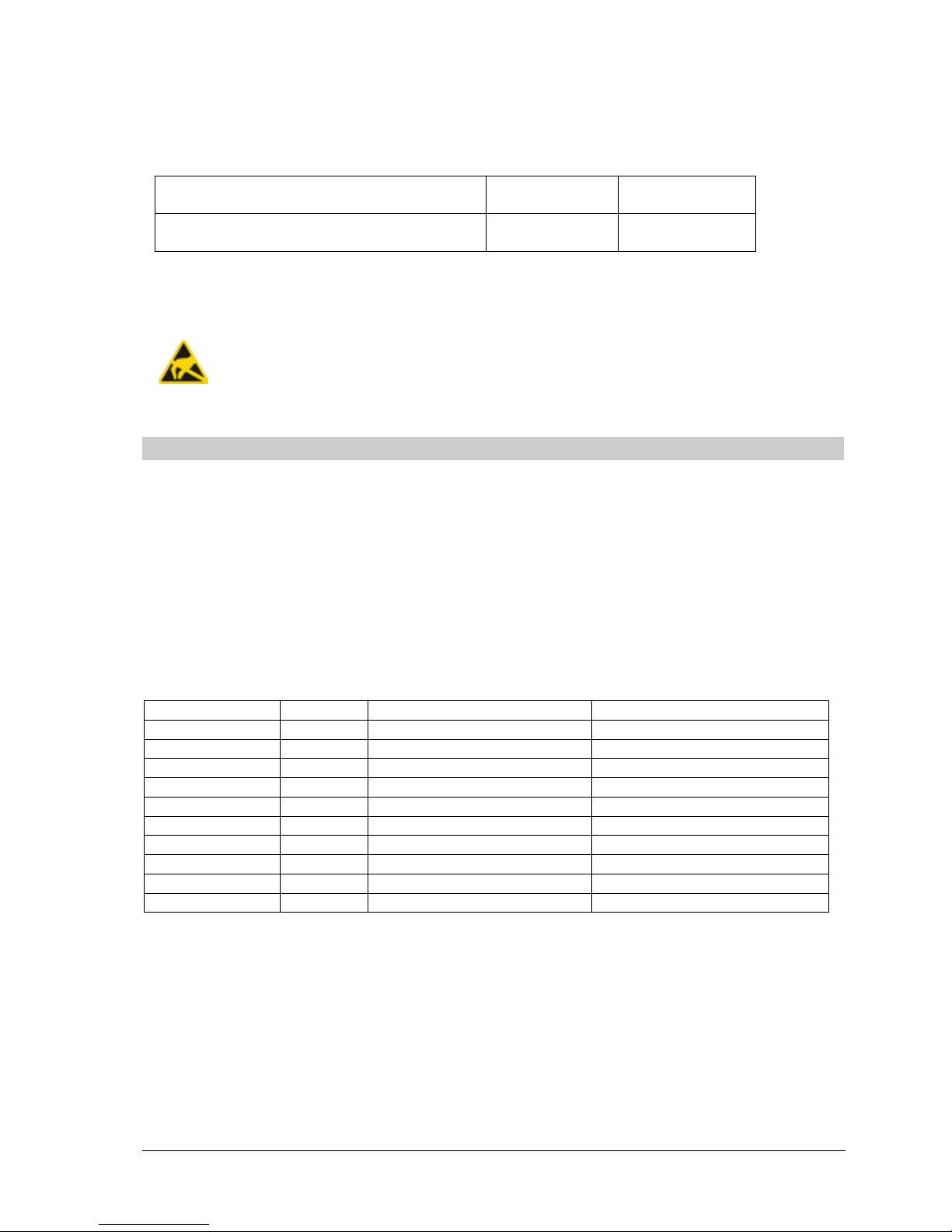
Table 1: Process structure
Connection terminal small –
bus connection , optional inputs
AWG 20 - 28 0.08 – 0.5 mm²
Connection terminal large –
external 24V input
AWG 12 - 20 0.5 – 2.5mm²
The bus circuit board DiM-10 is equipped with RS485 transceivers. For that reason the internal
length of the stub cable does not affect the signal quality of the bus segment.
Pay attention to the ESD protection of the bus circuit board. Especially good personal
earthing is required.
If the bus circuit board is disassembled from its housing transport and storage must
meet ESD requirements.
3.3 Bus cable
Only cables according to IEC 61158 and 61784 standards, cable type A, may be used for Profibus
DP wiring.
A maximum of 32 devices can be connected to a segment. If more devices should be connected
to the Profibus connect the segments using repeaters. Respect a distance of minimum 20 cm
between the bus cable and other cables. If possible, bus cables should be laid in a separate,
conductive, and earthed cable tray.
Make sure to avoid potential differences between the individual devices on the bus (perform a
potential equalisation).
For Profibus wiring the directives for segment length and maximum spur/stub length have to be
observed.
Bitrate [kbit/s]
Bit time
Max. segment lengt
h [m] Max. stub length [m]
9,6 104 µs 1200 500
19,2 52 µs 1200 500
45,45 22 µs 1200 100
93,75 10.6 µs 1200 100
187,5 5.3 µs 1000 33
500 2 µs 400 20
1500 666 ns 200 6,6
3000 333 ns 100 6000 166 ns 100 12000 83 ns 100 -
Connection data:
Strip length: 5 to 6 mm
Wire insertion angle relative to PCB: 40°
Connection technology: CAGE CLAMP® PCB terminal with slider
(WAGO series 218)
Cross section (solid-conductor): 0.08 to 0.5 mm²; AWG 28 to 20
Cross section (multi-conductor): 0.08 to 0.5 mm²; AWG 28 to 20
Cross section (multi-conductor): up to 0.25 mm², AWG 28 to 23
(ferrule without plastic shroud allowed)
Page 9
DREHMO - MaticC Profibus DPV0/DPV1 Page 9 of 28
Complementary operating manual
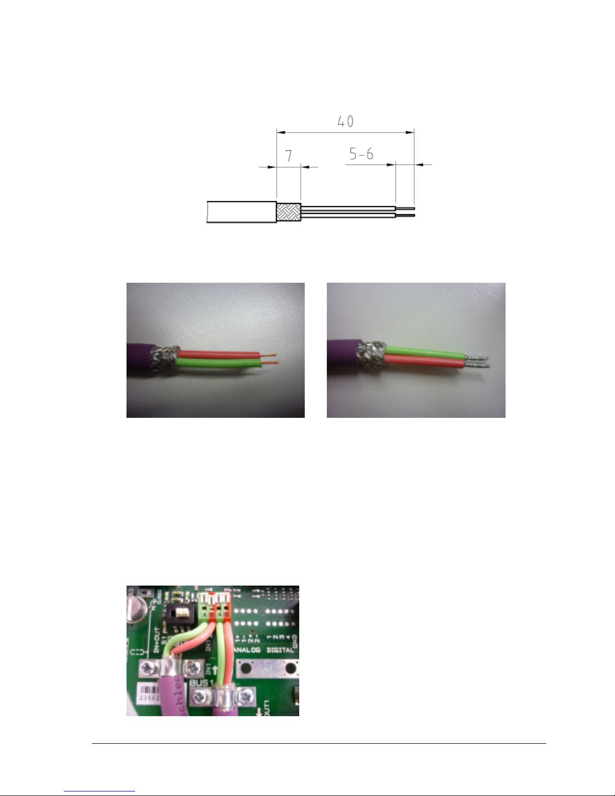
Connection:
- Insertion of the PROFIBUS cable trough the cable glands
- The shielding clamps for the PROFIBUS cables have to be removed
- The PROFIBUS cable and wires have to be prepared according the following drawing
all measurements in mm
Preparation of the PROFIBUS cable and wires
without ferrule with ferrule
Pictures:
PROFIBUS cable without ferrule and multi-conductor with ferrule
- In order to open the terminal contact, the slider has to be pushed forward or the contact
spring (in front of the slider) has to be pushed down with a screwdriver (blade width 2.5 to
3.5 mm)
- The PROFIBUS wire has to be inserted in an angle of approximately 40° relative to the
PCB board plane into the terminal. The slider has to be pushed backwards afterwards to
fasten the conductor (if a ferrule without plastic shroud is used, due to the commonly
ferrule length of approx. 7mm, the conductor isolation doesn’t immerge totally inside the
terminal inlet).
Picture: PROFIBUS terminals
Page 10
DREHMO - MaticC Profibus DPV0/DPV1 Page 10 of 28
Complementary operating manual
- The shielding of the PROFIBUS cable has to be tightened securely by means of the
respective cable clamps
- The cable glands have to be fastened with the prescribed torque value in order to
guarantee the specified IP grade.
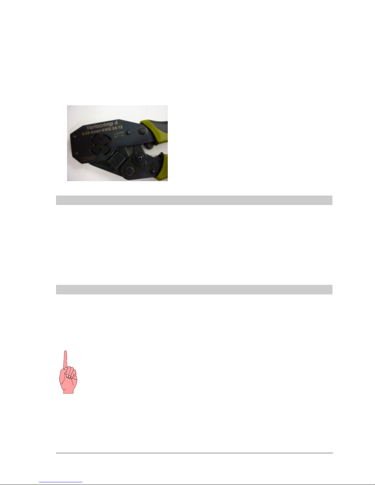
For the crimping of the ferrules we recommend the usage of the crimping tool from company
WAGO - Variocrimp 4. Uniform, compact crimping on all four sides for high conductor retention is
best suited for the used terminals.
3.4 Shield connection
The strain relief clamps for the PROFIBUS cable and the A/D input cable may be used for the
cable shielding – instead of the preferred usage of EMC cable glands. The strain relief clamps are
electrical connected via a RC combination to the housing. By means of this, highly frequent
signals can be deflected to the housing. Current flow over the shielding due to stray electric
currents in the overall plant installation can be avoided. In case of a good potential equalization
between the connected field devices, the RC combinations can be short-circuit via the according
switches in order to have an optimized conduction of possible disturbance signals from the cable
shield to the housing.
3.5 Bus termination
RS485 segments have to be terminated and conditioned at the beginning and the end in order to
define the signal levels and avoid signal reflections. On the appropriate actuators, the termination
switch S1 for BUS1 and S2 for BUS2 has to be in position „TERM“ (termination active). If the
termination is active, the outgoing PROFIBUS signal is decoupled from the incoming signal. By
means of this, subsequent field devices are disconnected from the master. If subsequent field
devices are existing, the termination switch S1 resp. S2 have to be in the position „IN=OUT“
(termination inactive).
Active conditioning of the fieldbus signals in case of activated termination is only given, if
the actuator electronic is powered via the mains power connection or the optional
existing external 24V DC supply.
Page 11
DREHMO - MaticC Profibus DPV0/DPV1 Page 11 of 28
Complementary operating manual
3.6 Additional conventional I/O interface (parallel interface)
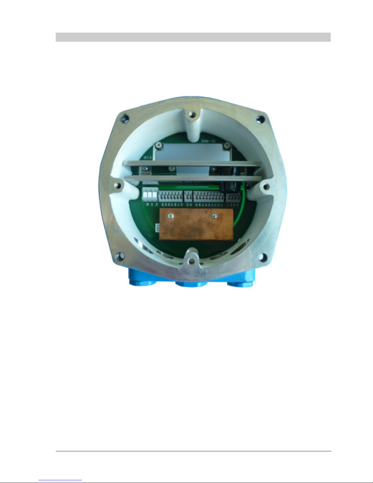
If the actuator is equipped with a conventional I/O interface in parallel to the PROFIBUS
connection, there is a separate intermediate connector housing mounted between the compact
plug cover and the actuator housing. By means of this, additional wiring space and additional
available cable entries are given. Separate connectors for the conventional input and output
signals according to the wiring diagram are mounted on an additional PCB.
Picture: Intermediate connector housing with the integrated PCB connector board for the
conventional I/O signals
The mains power connector in those applications is no longer mounted inside the compact plug
cover. Instead it is mounted on the connector board for the conventional I/O signals inside the
intermediate connector housing.
The PROFIBUS signals are wired from the actuator housing side towards the compact plug cover
side through the intermediate housing via an additional D-Sub connector cable.
Page 12
DREHMO - MaticC Profibus DPV0/DPV1 Page 12 of 28
Complementary operating manual
4 Switches / LED’s of the interface board
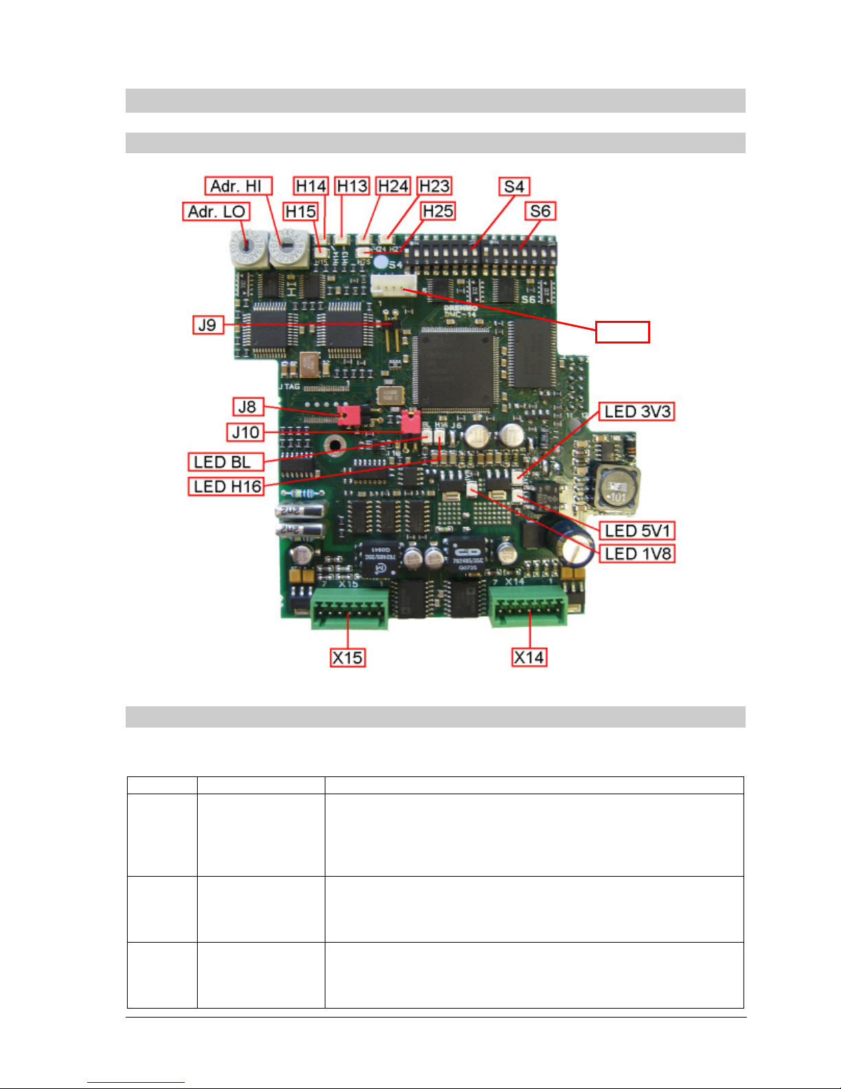
4.1 Location of the components on the interface board
4.2 Jumper
The system behaviour can be controlled by 3 jumpers. They are marked as follows:
Jumper
Meaning
Description
J8 HW-Watchdog
Reset out
Routes the Reset output of the external watchdog supervisory
circuit to the reset input of the controller. This enables the
watchdog circuit to reset the controller in case of under voltage
or watchdog tripping. For normal operation this jumper must be
closed.
J9 Bootloader Jump Causes the controller to enter the bootloader routines upon
system restart for firmware download. This disables the user
code from executing. For normal operation this jumper must be
open.
J10 HW-Watchdog
Watchdog in
Routes the controller generated watchdog trigger signal to the
supervisory circuit. This enables the external watchdog logic. If
the jumper is left open the external watchdog logic will be
disabled. For normal operation this jumper must be closed.
TEST
Page 13
DREHMO - MaticC Profibus DPV0/DPV1 Page 13 of 28
Complementary operating manual
4.3 DIL-Switches
4.3.1 Profibus Address HI / LO
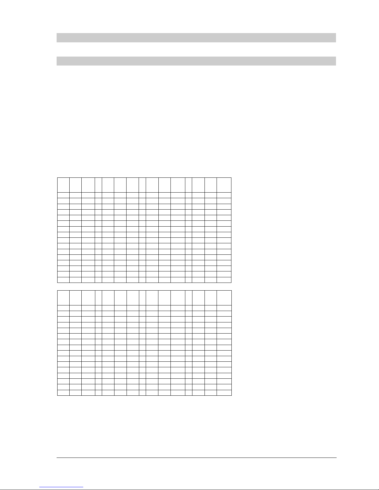
The Profibus address is controlled via the hexadecimal coded switches hex switch Adr. HI + LO.
The switch marked with HI sets the higher nibble, the switch marked with LO sets the lower nibble
of the address value.
The switches control the basic address of the primary channel, from witch, depending on the
selected redundancy concept, the address of the higher channel is calculated.
The basic address can be selected in a range from 2 to 125. Settings out of this given range are
not permitted and disable the Profibus interface. If the address of the second channel is
calculated with an offset of 64 the Bit 2 of the HI Nibble switch is masked out. Therefore only
settings in the range of 2 to 61 make sense in this case. For the second channel the bit 2 is forced
resulting in an address range from 66 to 125 for this channel.
Possible address settings:
HI
LO
ADR
HI
LO
ADR
HI
LO
ADR
HI
LO
ADR
0 0 NA 1 0 16 2 0 32 3 0 48
0 1 NA 1 1 17 2 1 33 3 1 49
0 2 2 1 2 18 2 2 34 3 2 50
0 3 3 1 3 19 2 3 35 3 3 51
0 4 4 1 4 20 2 4 36 3 4 52
0 5 5 1 5 21 2 5 37 3 5 53
0 6 6 1 6 22 2 6 38 3 6 54
0 7 7 1 7 23 2 7 39 3 7 55
0 8 8 1 8 24 2 8 40 3 8 56
0 9 9 1 9 25 2 9 41 3 9 57
0 A 10 1 A 26 2 A 42 3 A 58
0 B 11 1 B 27 2 B 43 3 B 59
0 C 12 1 C 28 2 C 44 3 C 60
0 D 13 1 D 29 2 D 45 3 D 61
0 E 14 1 E 30 2 E 46 3 E 62
0 F 15 1 F 31 2 F 47 3 F 63
HI
LO
ADR
HI
LO
ADR
HI
LO
ADR
HI
LO
ADR
4 0 64 5 0 80 6 0 96 7 0 112
4 1 65 5 1 81 6 1 97 7 1 113
4 2 66 5 2 82 6 2 98 7 2 114
4 3 67 5 3 83 6 3 99 7 3 115
4 4 68 5 4 84 6 4 100 7 4 116
4 5 69 5 5 85 6 5 101 7 5 117
4 6 70 5 6 86 6 6 102 7 6 118
4 7 71 5 7 87 6 7 103 7 7 119
4 8 72 5 8 88 6 8 104 7 8 120
4 9 73 5 9 89 6 9 105 7 9 121
4 A 74 5 A 90 6 A 106 7 A 122
4 B 75 5 B 91 6 B 107 7 B 123
4 C 76 5 C 92 6 C 108 7 C 124
4 D 77 5 D 93 6 D 109 7 D 125
4 E 78 5 E 94 6 E 110 7 E NA
4 F 79 5 F 95 6 F 111 7 F NA
NA) This combination is not permitted.
Page 14
DREHMO - MaticC Profibus DPV0/DPV1 Page 14 of 28
Complementary operating manual
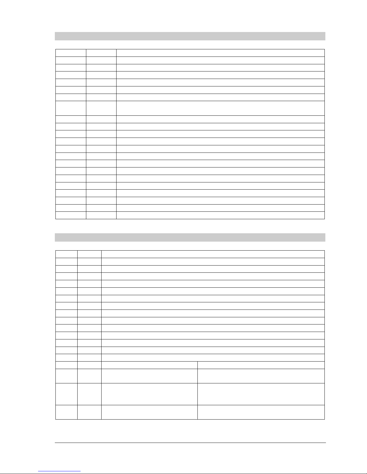
4.3.2 DIL Switch S4
Bit Value
Description
1
Enable Host communication
0 Host communication disabled. (Only for testing purposes)
1 Host communication enabled. (Default)
3..2
Reserve
d
6..4
Fail safe
delay time
(Added to the watchdog timeout provided by the Profibus Master)
000 0 Seconds
001 5 Seconds
010 10 Seconds
011 20 Seconds
100 40 Seconds
111 Fail safe disabled
7
Fail Safe behaviour on GCC (Global Control Clear)
0 Fail as is on GCC
1 Fail safe on GCC
8
Simulate external diagnosis
0 No simulation of external diagnosis (default)
1 Simulate external diagnosis (only for testing purposes)
4.3.3 DIL Switch S6
Bit Value
Description
1 Ad
dress
offset
of second
Profibus
channel
(Only for Dual ASIC)
0 No address offset for second channel
1 Address offset 64 for second channel
1
Line redun
dancy monitoring/switching (only if S6.4 and S6.5 = 1)
0 Use fast monitoring/switching mechanism
1 Switch channel only in case of slave watchdog tripping
3..2
PNO ID
selection for emulation mode
00 Matic C DPV1 (DUAL ASIC: 0x0C26 / SINGLE ASIC: 0x0C27)
01 Matic C DPV0 (0x0686)
10 AUMA (0x05CD)
11 SIPOS (DUAL ASIC: 0x056E / SINGLE ASIC: 0x056D)
5..4
Redundan
cy mode
Proto
col
/ Medi
a access
Dual ASIC
Single ASIC
00 DREHMO redundancy
GSD-File: DREM0C26
No redundancy; 1 ASIC on channel 1
GSD-File: DREM0C27
01 System redundancy acc. PNO
Spec. 2212
GSD-File: DREM0C26
No redundancy; 1 ASIC on channel 1
GSD-File: DREM0C27
10 ABB redundancy
GSD-File: DREM0C26
No redundancy; 1 ASIC on channel 1
GSD-File: DREM0C27
Page 15
DREHMO - MaticC Profibus DPV0/DPV1 Page 15 of 28
Complementary operating manual
11 Line redundancy (1 ASIC oper.)
GSD-File: DREM0C27
Line redundancy
GSD-File: DREM0C27
6
Redundan
cy response
(o
nly if
S6
.4 and S6.5 = 1
)
0 Redundancy reply on active channel
1 Redundancy reply on both channels
7
Position
output
Profibus
0 Output limited to 0..1000 or 46..230
1 Output with over- / underflow
4.4 Diagnosis LED’s
4.4.1 LED 1V8, 3V3 und 5V1
These LED group indicates the presence of the different supply voltages. For accurate operation
the presence of all voltage levels is essential. If one or more of these LED’s are off, this indicates
a serious damage.
4.4.2 LED BL
The LED indicates the correct program execution flow with a flash rate of 1Hz. If the LED keeps
off the user program is not executed. In this case the interface board either is malfunctioning, the
Firmware is missing or the Bootloader mode for firmware download is activated.
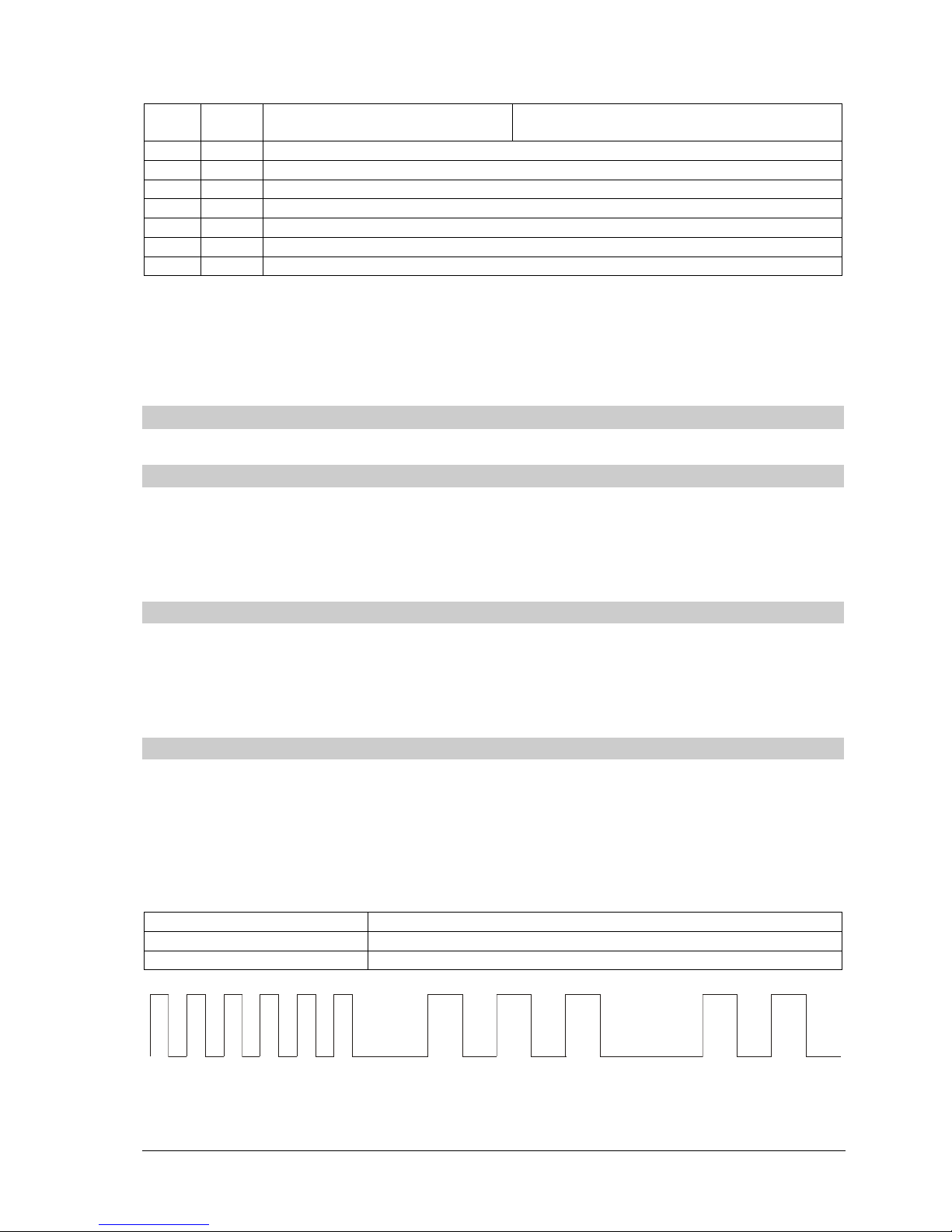
4.4.3 LED H16 DIAG
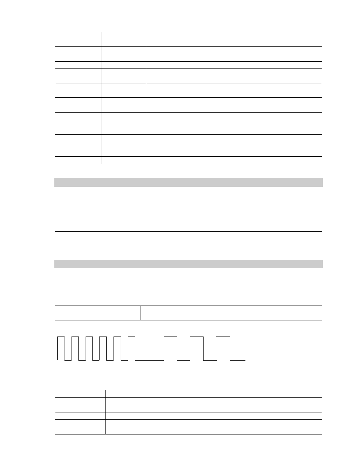
The LED indicates possible failures by flashing with two different frequencies. If the LED is off no
failure is recognized by the controller logic.
If more than one failure is recognized always the failure with the lowest group / code will be
signalled.
Flash code
Fast flash Start of sequence
First slow sequence Failure group
Second slow sequence Failure code
Start Failure group Failure code
Page 16
DREHMO - MaticC Profibus DPV0/DPV1 Page 16 of 28
Complementary operating manual
Fa
ilure group
Failure code
1
Pulse
System
fai
lures
1 RAM-Test Failure. The internal memory test failed.
2 Failure test ASIC channel 1
3 Failure test ASIC channel 2
4 NV-Memory failure. Failure accessing the non volatile
memory.
5 Hardware data failure. The hardware settings of the board are
missing.
2
Pulses
Configuration failures
1 Host communication disabled. S4.1 = 0
2 Invalid Profibus address
3 Board not equipped with necessary hardware
4 Board not equipped with necessary medium voter
3
Pulses
Application failures
1 Communication to host timed out
4.4.4 LED H13/H23 (Yellow)
The LED indicates, depending on the selected redundancy concept, the primary channel of the
interface. On single channel interface boards the LED H13 is always on.
Dual ASIC
Single ASIC
with line redundancy
H13 ASIC 1 is primary ASIC accesses media via BUS 1
H23 ASIC 2 is primary ASIC accesses media via BUS 2
4.4.5 LED H14/H24 Profibus physically state (Green)
The LED indicates the physical state of the respective Profibus channel. H14 indicates the state of
channel 1, H24 the state of the channel 2.
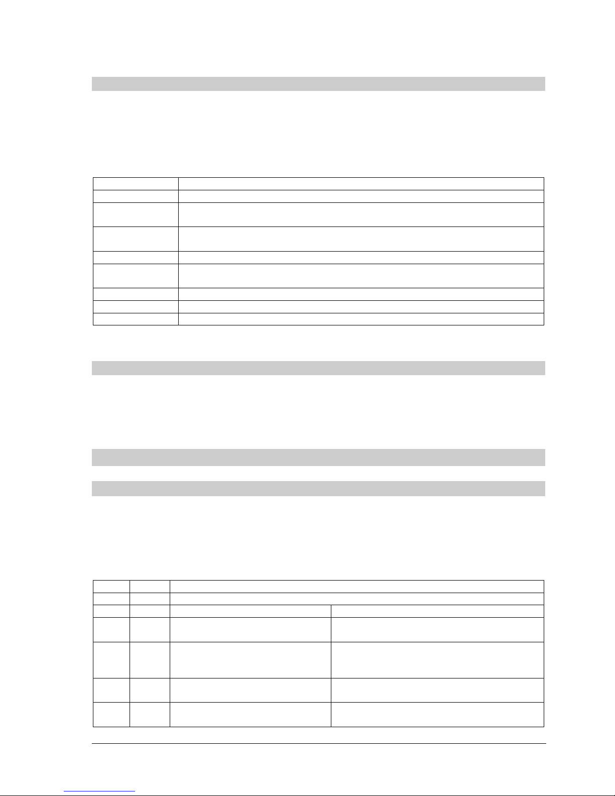
The LED displays the state by flashing with two different frequencies or it is permanent on or off.
Fast flash Start of sequence
First slow sequence State code
Start State code
The following states will be signalled:
H14/H24
State
Off Board is not equipped with ASIC for this channel or the ASIC is disabled
1 Pulse Profibus ASIC is in state Reset
2 Pulses Profibus ASIC is in state Passive Idle
3 Pulses Profibus ASIC is in state baud rate detection
On Profibus ASIC has detected a valid baud rate
Page 17
DREHMO - MaticC Profibus DPV0/DPV1 Page 17 of 28
Complementary operating manual
4.4.6 LED H15/H25 Profibus protocol state (Green)
The LED indicates the protocol state of the respective Profibus channel. H15 indicates the state of
channel 1, H25 the state of the channel 2. The LED indicates the states as described in the
former chapter.
The following states will be signalled:
H15/H25
State
Off For channel state please refer to LED H14/H24
1 Pulse Profibus ASIC is in state WaitPrm. No SetPrm telegram or a SetPrm with
invalid PNO-ID was received.
2 Pulses Profibus ASIC is in state WaitPrm. A SetPrm telegram with invalid
parameters was received.
3 Pulses Profibus ASIC is in state WaitCfg. No CheckCfg telegram was reveived.
4 Pulses Profibus ASIC is in state WaitCfg. A CheckCfg telegram with invalid
configuration was received.
5 Pulses Profibus ASIC is in state GCC. A GCC telegram was received
6 Pulses General failure in state machine/Illegal state.
On Profibus ASIC is in state Data Exchange.
4.4.7 TEST connector
The TEST connector offers extended diagnostic and update possibilities in combination with the
DREHMO USB adapter and the PC-Tool Matic C Operator.
5 Profibus Interface
5.1 GSD-Files
For device integration into engineering tools different GSD-files are available. The selection of the
right GSD file depends on the equipment of the interface board (1 or 2 ASIC’s) and the selected
redundancy concept setting via S6.4 and S6.5. The number of ASIC’s can be determined by
looking at the interface board. The ASIC’s are the square chips located beneath the coding
switches for the bus address.
S6
Bit Value
Redundancy mode Protocol / Media access
5..4
Dual ASIC
Single ASIC
00 DREHMO redundancy
GSD: DREM0C26
No redundancy; 1 ASIC on channel 1
GSD: DREM0C27
01 System redundancy acc. PNO
Spec. 2212
GSD: DREM0C26
No redundancy; 1 ASIC on channel 1
GSD: DREM0C27
10 ABB redundancy
GSD: DREM0C26
No redundancy; 1 ASIC on channel 1
GSD: DREM0C27
11 Line redundancy (1 ASIC oper.)
GSD: DREM0C27
Line redundancy
GSD: DREM0C27
Page 18
DREHMO - MaticC Profibus DPV0/DPV1 Page 18 of 28
Complementary operating manual
Remark:
The list of GSD files is only valid for PNO ID selection Matic C DPV1 according S6.2=0 and
S6.3=0.
5.2 Set parameter telegram
5.2.1 Standard parameter (7 Bytes)
The Profibus interface supports parameterization with different PNO-IDs in Byte 5 and 6 of the
standard parameters, which can be set by DIL switch S6.
This enables the operation of the device with control stations using 3rd party parameterizations.
The other bytes of the standard parameters have the meaning as described in Profibus
specifications.
Single ASC
Dual ASIC
PNO Id of
0C27 0C26 Matic C DPV1
0686 0686 Matic C DPV0
05CD 05CD AUMA
056D 056E SIPOS
5.2.2 User specific parameters (UsrPrm data)
The interface accepts a different amount of user parameter data:
Len
gth Usr_Prm
Description
3
80 00 00
Default value.
3 DPV1 bytes.
5
00 00 00
00 00
Matic C DPV0 compatible
3 DPV1 bytes.
Matic C DPV1 user specific (Reserved, always = 00)
4
80 00 00
00
Sipos compatible
3 DPV1 bytes.
Sipos user specific (Activation of internal position controller (If
equipped). 00=disabled; 01=enabled)
37
80 00 00
00 .. 00
AUMA compatible
3 DPV1 bytes.
34 bytes acc. AUMA GSD
The parameter telegram can be extended with a block of 8 bytes for the parameterization by the
RedCom layer.
Page 19
DREHMO - MaticC Profibus DPV0/DPV1 Page 19 of 28
Complementary operating manual
5.3 Process images
5.3.1 PPO1: (Default)
This process image has no command STOP for the version V005 (internal position
controller). Carefully check the setting of the DIL switch S1.1 in conjunction with the switch
S2.8 on the base plate. If S2.8 is 1 the switch S1.1 must be set to 0. In case of incorrect
settings malfunctioning of the device can occur.
This process image is activated by the following configuration:
Len
gth Cfg Description
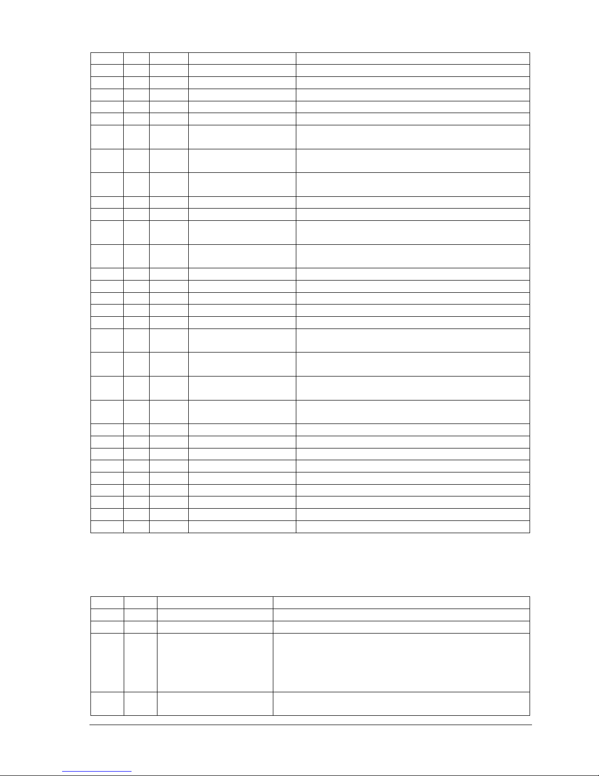
2 97 A3 Default value: 8 bytes input / 4 bytes output
2 53 61 SIPOS compatible: 4 words input / 2 words output
2 1B 23 AUMA compatible: 12 bytes input / 4 bytes output *)
*) Additional input bytes will be filled with 0.
Input data (Data from actuator to controller)
By
te Bit Cfg Signal
Description
0 0 All Final position OPEN Final position indication according to settings
1 All Final position CLOSE Final position indication according to settings
2..3 All Reserved
4 All Running OPEN Running indication OPEN
5 All Running CLOSE Running indication CLOSE
6 All Reserved
7 All Collective fault Collective fault indication
1 0 All Thermal protection Thermal motor protection tripped
1 97 A3 Collective fault 1 Collective fault according to settings
53 61 - 1B 23 - 2 All Mode REMOTE Actuator can be controlled by external commands
3 All Mode LOCAL Actuator can be controlled by local commands
4 All Position switch
OPEN
Final position indication
5 All Position switch
CLOSE
Final position indication
6 All Torque OPEN Torque monitoring tripped OPEN
7 All Torque CLOSE Torque monitoring tripped CLOSE
2 Actual position HI Actual position indication
3 Actual position LO (CLOSED = 0 Dez / OPENED = 1000 Dez)
4 0 All Illegal command Setpoint <0 or > 1000; Multiple commands *)
1 All Mode not REMOTE Actuator cannot be controlled by external
commands
2 All Thermal protection Thermal motor protection tripped
3 All - 4 All Torque OPEN Torque monitoring tripped OPEN
Page 20
DREHMO - MaticC Profibus DPV0/DPV1 Page 20 of 28
Complementary operating manual
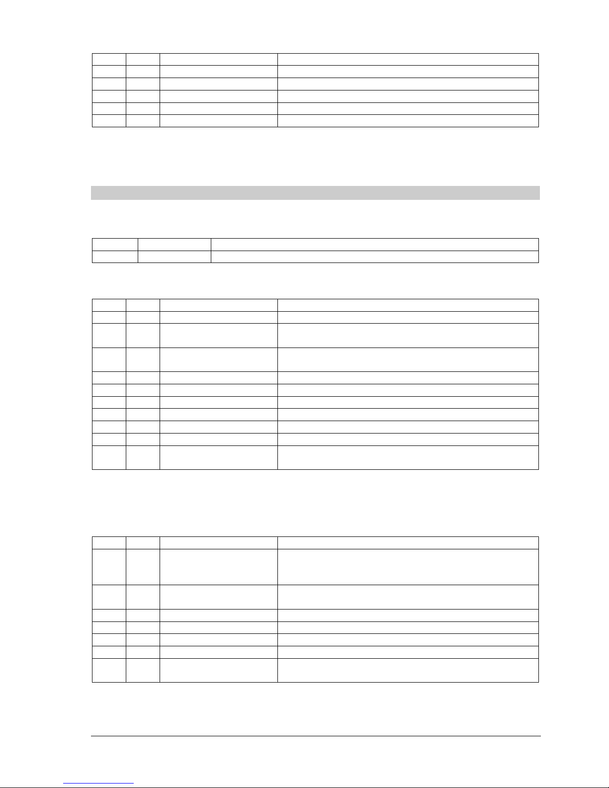
By
te Bit Cfg Signal
Description
5 All Torque CLOSE Torque monitoring tripped CLOSE
6 All CLEAR A Global control clear was received
7 All Reserved
5 0 All Reserved
1 All Channel 2 active Communication via channel 2 in redundancy
mode
2 All Failure position
feedback
Failure of combined sensor or position feedback
3 All Failure position
feedback
Failure of combined sensor or position feedback
4 All - 5 All - 6 All Hand wheel
operation
Actuator is moved by hand wheel *)
7 All Operation time
monitoring
Operation time OPEN / CLOSE exceeded *)
6 0 All Step pause Stepping mode pause *)
1 All Step proportional Stepping mode proportional mode *)
2 All Step operation Stepping mode operation *)
3 All Step area Actuator is within stepping area *)
4 All Running OPEN /
Intermediate pos. 1
Running indication OPEN (TR11 open) /
Intermediate position 1 (TR11 closed) ***)
5 All Running CLOSE /
Intermediate pos. 2
Running indication CLOSE (TR11 open) /
Intermediate position 2 (TR11 closed) ***)
6 All Local operation
OPEN
Actuator is running in OPEN direction in LOCAL
mode
7 All Local operation
CLOSE
Actuator is running in CLOSE direction in LOCAL
mode
7 0 All Digital input 0 **) Command STOP/AUTO
1 All Digital input 1 **) Command CLOSE
2 All Digital input 2 **) Command OPEN
3 All Digital input 3 **) Additional input E1
4 All Digital input 4 **) Additional input E2
5 All Digital input 5 **) Intermediate position 1
6 All Digital input 6 **) Intermediate position 2
7 All - -
*) Not supported yet
**) Only with PNO-ID Matic C and AUMA (S6.2 / S6.3), otherwise always = 0
***) Depending on TR11 setting on the base board of the control unit (from FW 1.05.0020 at DMC-14)
Output data (Data from controller to actuator)
Byte
Bit Signal
Description
0 0 Command OPEN Command OPEN, if AUTO = 0
1 Command CLOSE Command CLOSE, if AUTO = 0
2 Command AUTO
(V005)
Command STOP
(V003)
Activates the internal position controller
(Position controlling according setpoint / actual value
comparison)
Stops the actuator. (Signal has higher priority than
CLOSE and OPEN)
3 Fault acknowledge Reset mechanism for specific tripped faults. (e.g.
Torque tripping) *)
Page 21
DREHMO - MaticC Profibus DPV0/DPV1 Page 21 of 28
Complementary operating manual
4..7 Reserved
1 0..7 Reserved
2 Setpoint HI Position setpoint for positioner
3 Setpoint LO (CLOSE = 0 Dez / OPEN = 1000 Dez)
*) Not supported yet
5.3.2 PPO2: (Matic C compatible)
This process image is activated by the following configuration:
Len
gth Cfg Description
2 21 11 Default value: 2 bytes input / 2 bytes output
Input data (Data from actuator to controller)
Byte
Bit S
ignal
Description
0 0 Collective fault Collective fault indication
1 Running OPEN /
Intermediate pos. 1
Running indication OPEN (TR11 open) /
Intermediate position 1 (TR11 closed) **)
2 Running CLOSE /
Intermediate pos. 2
Running indication CLOSE (TR11 open) /
Intermediate position 2 (TR11 closed) **)
3 Mode REMOTE Actuator can be controlled by external commands
4 Final position OPEN Final position indication according to settings
5 Final position CLOSE Final position indication according to settings
6 Switch off OK OPEN Switch off OK in OPEN direction *)
7 Switch off OK CLOSE Switch off OK in CLOSE direction *)
1 0..7 Actual position Position feedback
(CLOSE = 46 Dez / OPEN = 230 Dez)
*) Not supported yet
**) Depending on TR11 setting on the base board of the control unit (from FW 1.05.0020 at DMC-14)
Output data (Data from controller to actuator)
Byte
Bit Signal
Description
0 0 Command AUTO Activates the internal position controller
(Position controlling according setpoint / actual value
comparison)
1 Command STOP Stops the actuator. (Signal has higher priority than
AUTOMATIK, CLOSE and OPEN)
2 Command CLOSE Command CLOSE, if AUTO = 0
3 Command OPEN Command OPEN, if AUTO = 0
4..7 Reserved
1 0..7 Setpoint position setpoint for position controller
(CLOSE = 46 Dez / OPEN = 230 Dez)
Page 22

DREHMO - MaticC Profibus DPV0/DPV1 Page 22 of 28
Complementary operating manual
5.4 Acyclic data
The access on the acyclic parameters is possible by means of the DPV1 services MSAC1 and
MSAC2. The used data types are conform to the PROFIBUS-PA definitions.
A detailed listing of the overall acyclic data model is not given here, because the access out of the
PLC or DCS system is either done via a DDL (Device Description Language) or a DTM (Device
Type Manager).
DDL or DTM can be downloaded from the DREHMO homepage or can be ordered free of charge
via the DREHMO service.
Page 23
DREHMO - MaticC Profibus DPV0/DPV1 Page 23 of 28
Complementary operating manual
6 System functions
6.1 Diagnostics
PC based diagnosis is possible by means of a separate available dedicated USB adaptor kit in
conjunction with the PC tool Matic C Operator. Further details on that are given in the
corresponding manuals.
If the electronic is equipped with a PROFIBUS board, the interface connection has to be
done in any case via the TEST connector on the PROFIBUS interface board. The
interface connection on the main board is not available in this hardware configuration.
6.2 Firmware download
The following chapter describes deeper interventions into system functions. Thus the
described actions should be carried out only by professional well trained personnel.
Faulty operation or failures could result in major damages.
The controller located on the interface board offers the possibility to update the firmware for
system treatment or for the implementation of new functionality.
6.2.1 Required items
- Drehmo USB-Adapter-Kit
- Test plug SER01 with reset switch (included in Drehmo USB-Adapter-Kit)
- PC equipped with Windows operating system
- Programming software Matic C Operator
- HEX-File with new Firmware
6.2.2 Step by step description
1.) Power off actuator to avoid serious damages to the electronic due to high signal
differences
2.) Connect the serial Com-Port of the PC to the 5-pole
TEST connector of the interface board
3.) Power on the actuator
4.) Start PC Firmware Download Tool
Page 24
DREHMO - MaticC Profibus DPV0/DPV1 Page 24 of 28
Complementary operating manual
Downloading firmware using Matic C Operator
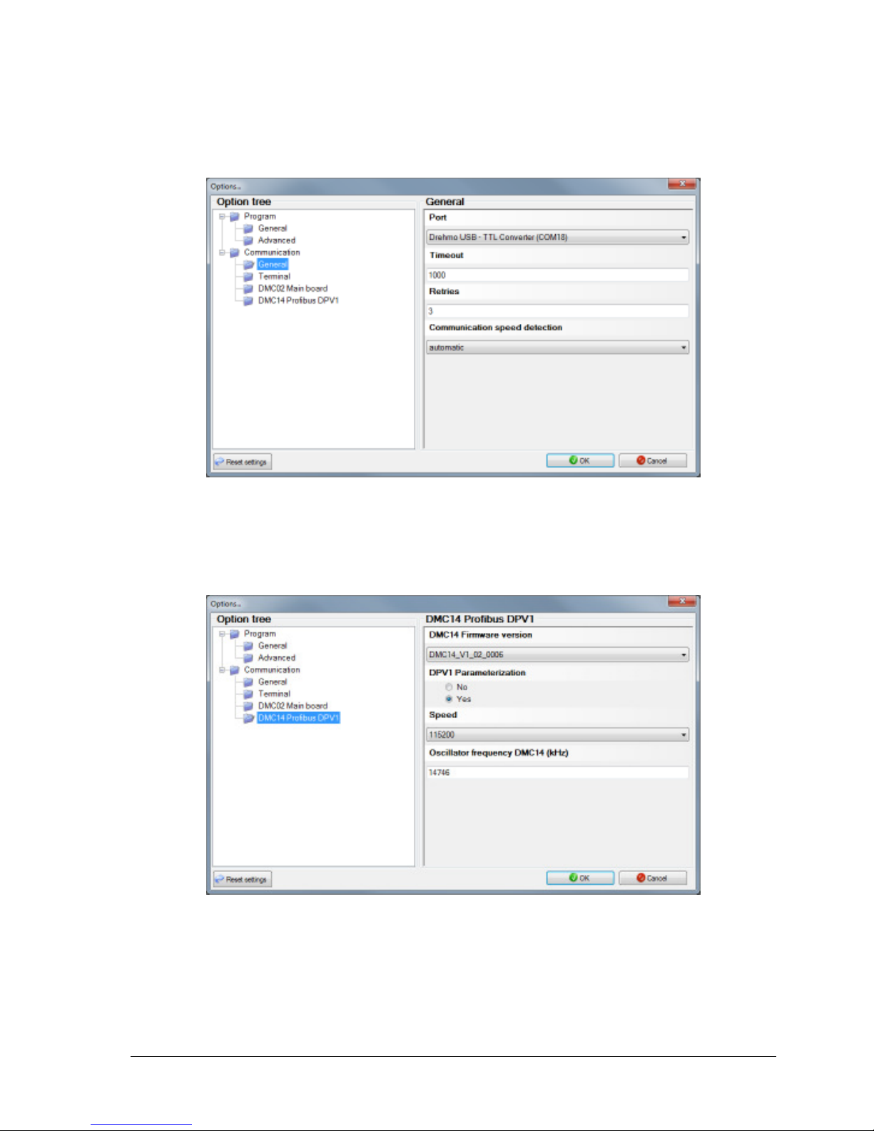
1.) Select the used communication port to which the RS232/TTL level converter is connected.
Communication port setting is done via menu entry Extras->Options. Within the option tree
the entry Communication -> General has to be selected.
2.) Choose the transmission speed for the entry DMC14 Profibus DPV1. The transmission
speed 115200 Baud is the highest selectable speed. This speed can only be used under
ideal circumstances. A save and secure connection can be achieved by selecting a speed
of 57600 Baud. If the connection still fails during the transmission it is advised to further
reduce the speed.
3.) Set the oscillator frequency in kHz. The controller of the interface board is equipped with
an oscillator frequency of 14746 kHz.
4.) Close the Options dialog by pressing the OK button.
5.) Choose the firmware download function by selecting the menu entry Service -> Firmware
download…
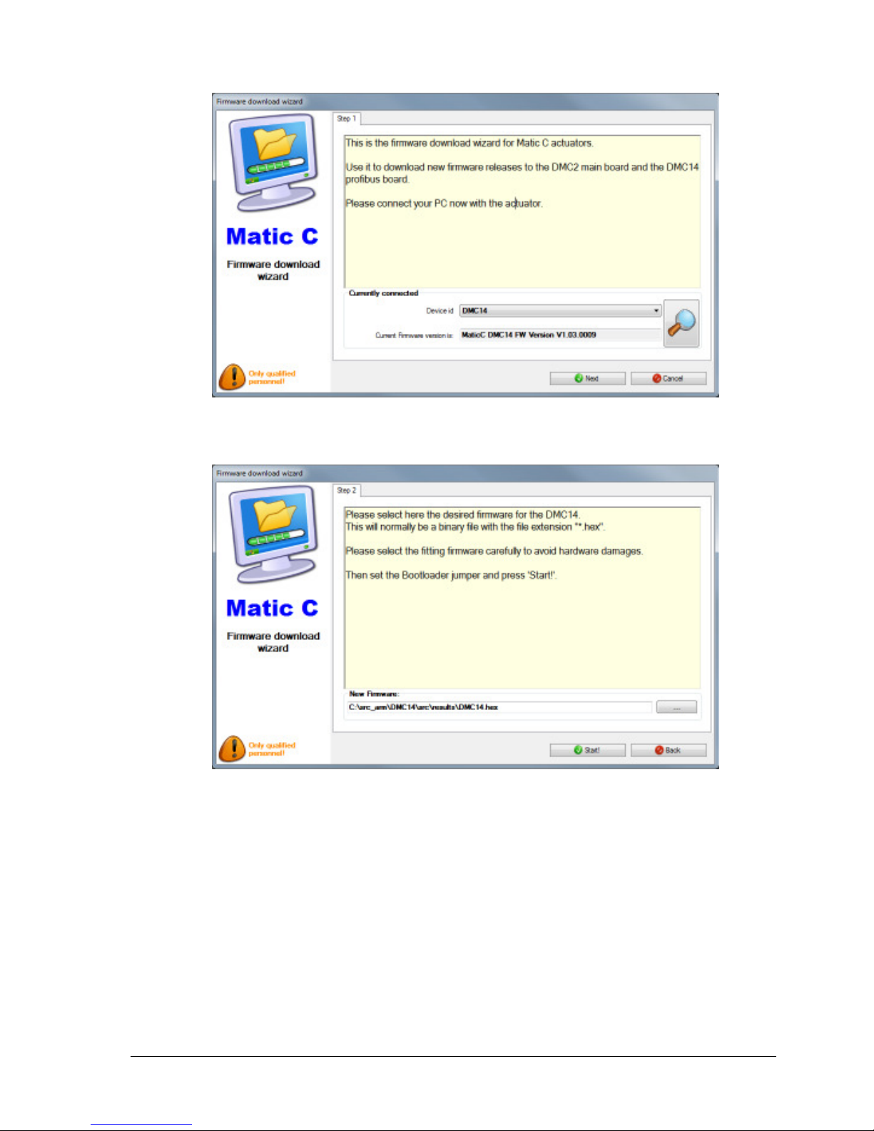
6.) The firmware download wizard will be displayed. The wizard tries to identify the type of the
attached target. If the detection fails manually select DMC14 for the device ID. Proceed by
clicking OK.
Page 25
DREHMO - MaticC Profibus DPV0/DPV1 Page 25 of 28
Complementary operating manual
7.) Choose the Hex File containing the binary data for download. A file open dialog can be
opened by clicking the button “...”.
8.) By clicking the button Start! the download will be started.
Page 26
DREHMO - MaticC Profibus DPV0/DPV1 Page 26 of 28
Complementary operating manual
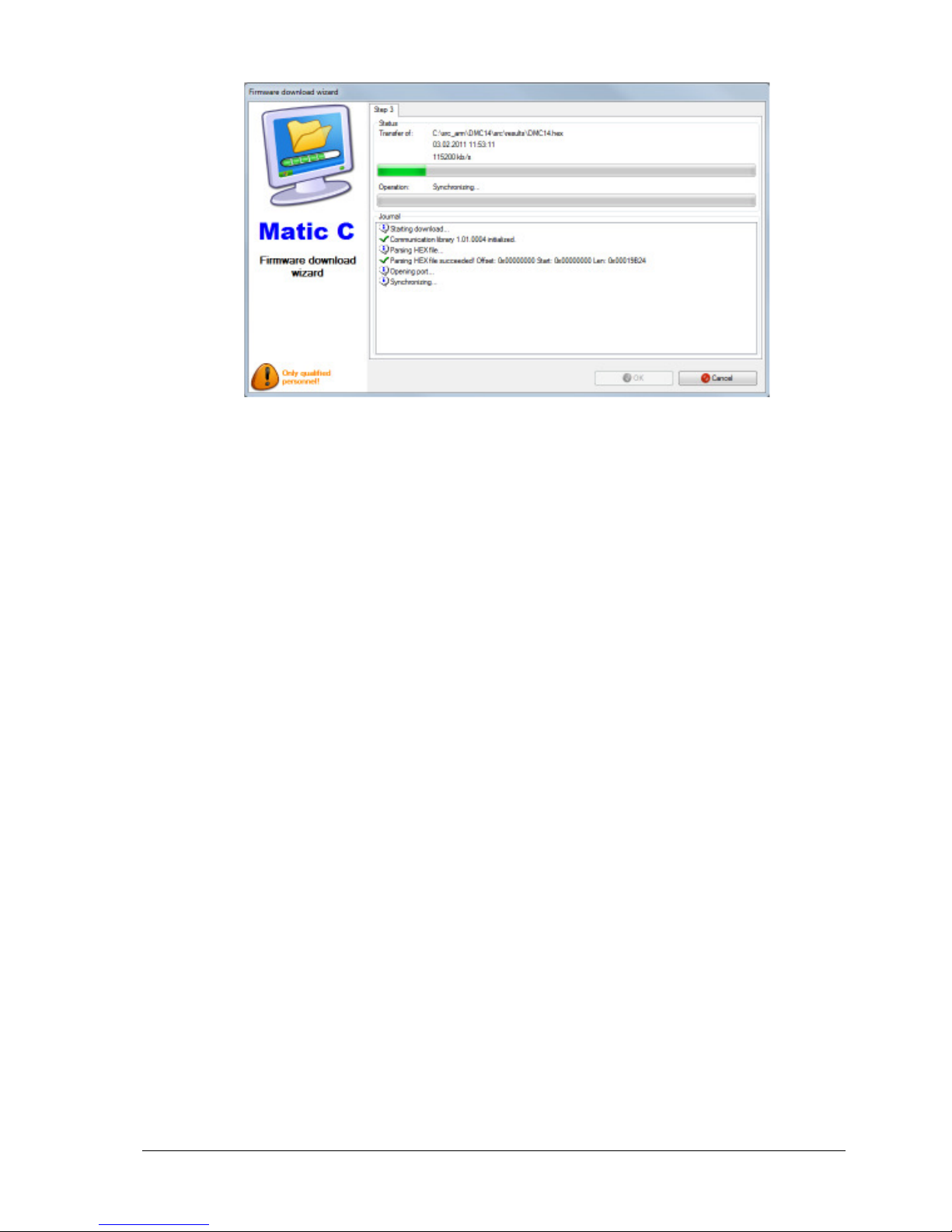
9.) The wizard tries to synchronize with the target first. If this synchronisation fails please
check the correct jumper displacement from position J8 to position J9. Press the reset
switch at the cable connected to the TEST connector for approx. 1s and release it.
Press the retry button.
10.) Firmware download starts. The progress will be displayed.
11.) When the download is finished this will be displayed.
12.) Power off the actuator and remove the connection to the PC.
13.) Remove jumper J9 and place it to J8.
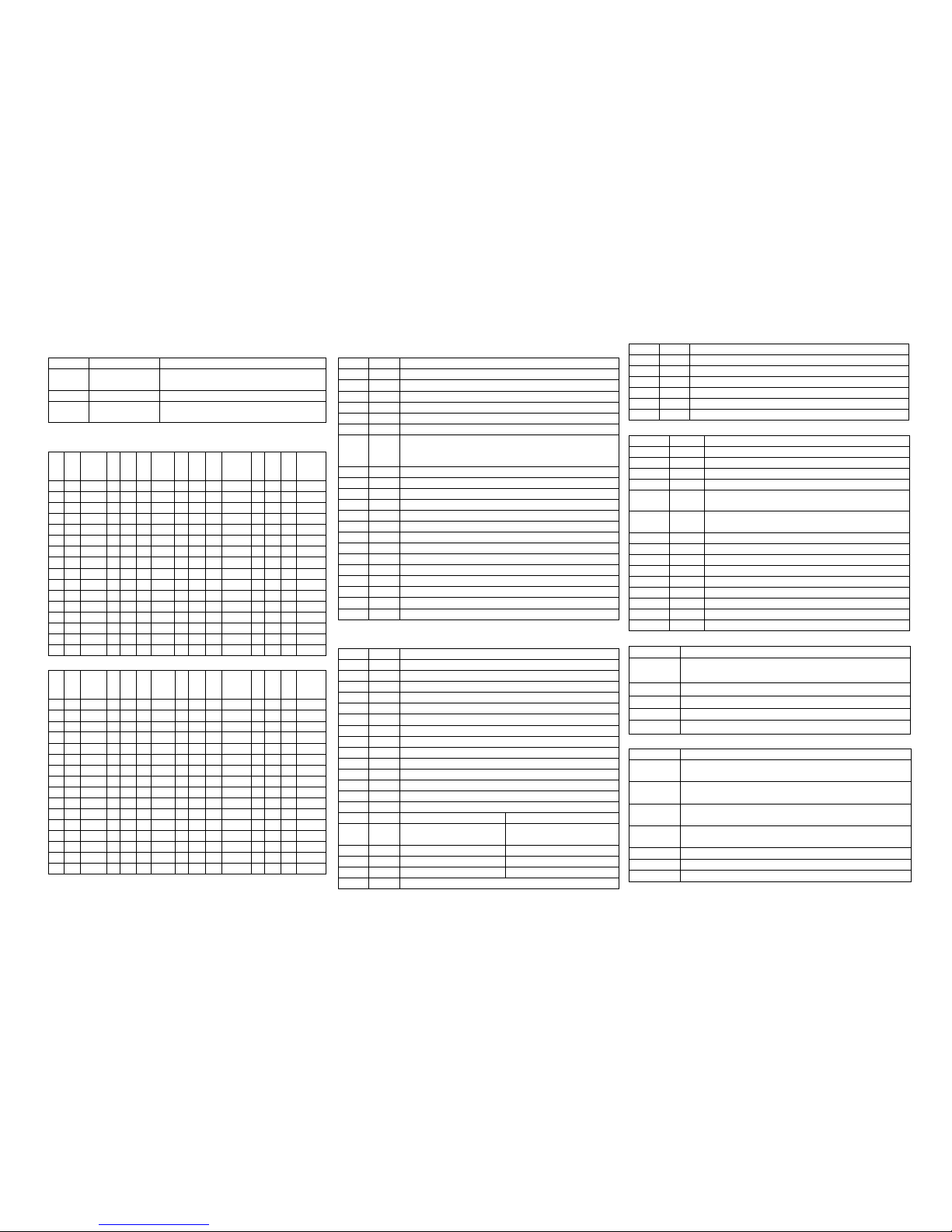
Page 27
Jumper
Jumper Meaning Description
J8 HW-Watchdog
Reset out
Reset-Output e
xternal watchdog
=> Reset Input controller
J9 Bootloader Jump
Start b
ootloader
r
outines
J10 HW-Watchdog
Watchdog in
Watchdog trigger output
=> External
watchdog circuit
Address settings:
HI LO
ADR
HI LO
ADR
HI
LO
ADR
HI LO
ADR
0 0 NA 1 0 16 2 0 32 3 0 48
0 1 NA 1 1 17 2 1 33 3 1 49
0 2 2 1 2 18 2 2 34 3 2 50
0 3 3 1 3 19 2 3 35 3 3 51
0 4 4 1 4 20 2 4 36 3 4 52
0 5 5 1 5 21 2 5 37 3 5 53
0 6 6 1 6 22 2 6 38 3 6 54
0 7 7 1 7 23 2 7 39 3 7 55
0 8 8 1 8 24 2 8 40 3 8 56
0 9 9 1 9 25 2 9 41 3 9 57
0 A 10 1 A 26 2 A 42 3 A 58
0 B 11 1 B 27 2 B 43 3 B 59
0 C 12 1 C 28 2 C 44 3 C 60
0 D 13 1 D 29 2 D 45 3 D 61
0 E 14 1 E 30 2 E 46 3 E 62
0 F 15 1 F 31 2 F 47 3 F 63
HI LO
ADR
HI LO
ADR
HI
LO
ADR
HI LO
ADR
4 0 64 5 0 80 6 0 96 7 0
112
4 1 65 5 1 81 6 1 97 7 1
113
4 2 66 5 2 82 6 2 98 7 2
114
4 3 67 5 3 83 6 3 99 7 3
115
4 4 68 5 4 84 6 4 100 7 4
116
4 5 69 5 5 85 6 5 101 7 5
117
4 6 70 5 6 86 6 6 102 7 6
118
4 7 71 5 7 87 6 7 103 7 7
119
4 8 72 5 8 88 6 8 104 7 8
120
4 9 73 5 9 89 6 9 105 7 9
121
4 A 74 5 A 90 6 A 106 7 A
122
4 B 75 5 B 91 6 B 107 7 B
123
4 C 76 5 C 92 6 C 108 7 C
124
4 D 77 5 D 93 6 D 109 7 D
125
4 E 78 5 E 94 6 E 110 7 E NA
4 F 79 5 F 95 6 F 111 7 F NA
NA) This setting is not available, thus invalid.
DIL Switch S4
Bit Val D
escription
1
Enable Host communication
0
Host communication disabled. (Only for testing purposes)
1
Host communication enabled. (Default)
3..2
Reserved
6..4
Fail safe delay time
(Added to the watchdog timeout provided by the Profibus
Master)
000 0
Seconds
001 5
Seconds
010 10
Seconds
011 20
Seconds
100 40
Seconds
111 Fail safe
disabled
7
Fail Safe behaviour on GCC (Global Control Clear)
0
Fail as is on GCC
1
Fail safe on GCC
8
Simulate external diagnosis
0 No simulation of external diagnosis (Default)
1
Simulation of external diagnosis (Only for testing purposes)
DIL Switch S6
Bit Val Description
1
Adrress offset of second Profibus channel
0
No address offset for second channel
1
Address offset 64 f
or second channel
1
Line redundancy monitoring (only if S6.4 and S6.5 = 1)
0
Use fast monitoring/switching mechanism
1
Switch channel only in case of slave watchdog tripping
3..2
PNO ID selection for emulation mode
00
Matic C DPV1 (DUAL AS
: 0
x0C26 / SINGLE AS: 0x0C27)
01
Matic C DPV0 (0x0686)
10
AUMA (0x05CD)
11
SIPOS (DUAL ASIC: 0x056D / SINGLE ASIC: 0x056E)
5..4
Redundancy mode Protocol / Media access
Dual ASIC
Single ASIC
00
DREHMO
r
edundancy
GSD: DREM0C26
No redundancy
1 A
SIC
GSD: DREM0C27
01
System redundancy
(0C26) No redundancy
(0C27)
10
ABB redundancy
(0C26) No redundancy
(0C27)
11
Line redundancy
(0C27)
Line redundancy
(0C27)
6
Redundancy response (Only if S6.4 and S6.5 = 1)
0
Redundancy reply on active
channel
1
Redundancy reply on both channels
7
Position output Profibus
0
Output limited to 0..1000 or 46..230
1
Output with over
-
/underflow
LED H16 DIAG
Group C
ode
1 Imp. System failures
1
RAM-Test Failure. The internal memory test failed
.
2
Failure test ASIC channel 1
3
Failure test ASIC channel 2
4 NV-
Memory failure. Failure accessing the non
volatile
memory.
5
Hardware data failure. The hardware settings of the board
are missing.
2 Imp.
Configuration failures
1
Host comm
unication disabled. S4.1 = 0
2
Invalid profibus address
3
Board not equipped with necessary hardware
4
Board not equipped with necessary medium voter
3 Imp.
Application failures
1
Communication to host timed out
LED H14/H24 Physical state Profibus
HX4 State
Off Board is not equipped with ASIC for this channel or the ASIC is
disabled
1 Pulse Profibus ASIC is in state Reset
2 Pulses Profibus ASIC is in state Passive Idle
3 Pulses Profibus ASIC is in state baud rate detection
On Profibus
ASIC has detected a valid baud rate
LED H15/H25 Protocol state Profibus
HX5 State
1 Pulse Profibus ASIC is in state WaitPrm. No SetPrm telegram or a
SetPrm with invalid PNO-ID was received.
2 Pulses Profibus ASIC is in state WaitPrm. A SetPrm telegram
with invalid
parameters was received.
3 Pulses Profibus ASIC is in state WaitCfg. No CheckCfg telegram was
reveived.
4 Pulses Profibus ASIC is in state WaitCfg. A CheckCfg telegram with
invalid configuration was received.
5 Pulses Profibus ASIC is in st
ate GCC. A GCC telegram was received
6 Pulses General failure in state machine/Illegal state.
On Profibus ASIC is in state Data Exchange.
Page 28
DREHMO GmbH
Zum Eichstruck 10
57482 Wenden/Germany
Tel.: +49 2762 9850-0
Internet: www.drehmo.com
eMail: [email protected]
 Loading...