

Drechselbedarf Schulte MIDI FU-350 Operating Instructions Manual
Original Operating Instructions
Midi FU -350
WOOD TURNING LATHE
Midi FU
Midi FU Midi FU
Midi FU ----350
350350
350
DRECHSELBANK
DRECHSELBANK DRECHSELBANK
DRECHSELBANK
....
Midi FU
Midi FU Midi FU
Midi FU ----350
350350
350
DRECHSELBANK
DRECHSELBANK DRECHSELBANK
DRECHSELBANK
....

Dear Customer,
Thank you for choosing the MIDI FU-350 wood lathe.
With the MIDI FU-350 you get a lathe that combines innovations with time-tested technology. The result of
the collaboration of experienced Turners and engineers is an excellent suitable lathe to a tremendously good
price-performance ratio for beginners, advanced, professionals and artists. Continued support is important
to us. In all issues relating to our products or services, we encourage you to contact us via phone or E-Mail.
We look forward to hearing from you. Your experience will enable us to improve the quality of the lathe even
further.
Best regards,
Drechselbedarf Schulte
D 49744 Geeste / Gr. Hesepe
Meppener Str. 111
Germany
Tel.: +49 (0) 59 37 / 91 32 34
Fax: +49 (0) 59 37 / 91 32 33
Homepage: www.drechselbedarf-schulte.de
Email: info@drechselbedarf-schulte.de
Notice:
Due to a continuous process of improvement the manufacturer reserves the right to implement changes to
the technical specications at any time and without prior notice, without any obligations arising for the manufacturer.
No part of this document may be copied or transmitted for any purpose whatsoever and irrespective of the
manner in which this is done.
- 2 -
© Drechselbedarf SchulteOriginal Operating Instructions V1.0

Index
Icon Legend ................................................................................................................................................. 4
Introduction .................................................................................................................................................. 4
1. Basic health and safety information...................................................................................................... 4
2. Intended use ......................................................................................................................................... 7
3. Technical data ....................................................................................................................................... 7
4. Functional description........................................................................................................................... 8
5. Protective devices ................................................................................................................................ 10
EMERGENCY STOP/OFF- and ON-function ....................................................................................... 10
Overview of furter protective devices .................................................................................................. 10
6. Requirements for the Set-up location .................................................................................................. 11
7. Installation of the lathe.......................................................................................................................... 12
Beschreibung der Drechselbank ......................................................................................................... 12
Montage der Bettverlängerung (optional erhältlich).............................................................................. 16
8. Conntection of the lathe to the power grid ........................................................................................... 17
9. Starting up ............................................................................................................................................ 17
10. Operation of the lathe ........................................................................................................................... 18
Headstock............................................................................................................................................. 18
Tailstock ................................................................................................................................................ 19
Hand rest ............................................................................................................................................. 19
Locking device (eccentric clamp) ....................................................................................................... 20
Spindle lock .......................................................................................................................................... 20
24-step part creation............................................................................................................................. 20
Mobile control box ............................................................................................................................... 21
Recommended speed range ............................................................................................................... 22
Speed range by means of pulley change ............................................................................................ 22
11. Care and maintenance ......................................................................................................................... 29
12. Decommissioning ................................................................................................................................. 30
13. Terms of warranty ................................................................................................................................. 30
14. Malfunctions ......................................................................................................................................... 31
15. Annex.................................................................................................................................................... 32
Annex 2 Spare parts list........................................................................................................................ 33
Anlage 3 Schaltplan ............................................................................................................................. 36
Anlage 4 Maße Befestigung für betreiberseitiges Untergestell ............................................................ 38
© Drechselbedarf Schulte Original Operating Instructions V1.0
- 3 -
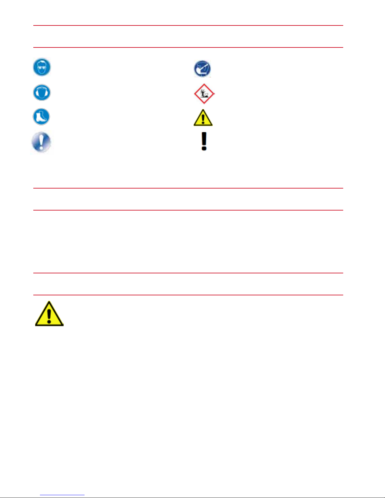
Explanation of symbols
Introduction
1. Basic health and safety information
Wear eye protection
Wear ear protection
Wear safety shoes
Damage or hazards for persons,
lathe, material or the environment
This manual contains instructions for the installation, safety precautions, general operating instructions,
instructions for maintenance and a spare parts list. The concept and the construction of the Midi FU - 350
is designed to allow you a trouble-free work for years if you take into account the recommendations in this
guide.
The non-observance of the following rules and warnings, as well as the safety instructions listed in this manual and attached to the machine, can lead to serious injury.
• In the interest of your own safety.
Read the instructions before starting the installation or machine operation. Please keep the instructions
safe and if you pass the lathe to others, make sure you provide the instruction manual with it.
• Do not make any technical modications.
The machine is designed exclusively for working with wood. Get to know the scope and the limitations of
the machine and related special dangers connected therewith. There are no direct or indirect guarantee
and warranty claims against the seller if the unit is used improperly or used outside the intended purpose.
In addition, the seller is not liable for injuries that may arise from the unintended use.
• Familiarise yourself with the working methods and functioning before initial start up.
If you are not familiar with the function of a lathe, you should seek expert support. An instruction by
someone competent in dealing with lathes is highly recommended. The Corporation Drechselbedarf
Schulte offers appropriate courses for you.
• The minimum age for users of the lathe is 16 years old.
Wear breathing protection
Environmentally hazardous substances
Immediate health hazards
and serious injury
Important note
- 4 -
© Drechselbedarf SchulteOriginal Operating Instructions V1.0
Symbolerklärung
Augenschutz tragen Atemschutz tragen
Gehörschutz tragen Umweltgefährdende Stoffe
Sicherheitsschuhwerk tragen
Unmittelbare Gefahren für die Gesundheit
und ernsthaften Verletzungen
Symbolerklärung
Augenschutz tragen Atemschutz tragen
Gehörschutz tragen Umweltgefährdende Stoffe
Sicherheitsschuhwerk tragen
Unmittelbare Gefahren für die Gesundheit
und ernsthaften Verletzungen
Schäden bzw. Gefahren für
Personen, Drehbank, Material oder
Umwelt
Wichtiger Hinweis
Atemschutz tragen
Umweltgefährdende Stoffe
Unmittelbare Gefahren für die Gesundheit
und ernsthaften Verletzungen
Unmittelbare Gefahren für die Gesundheit
und ernsthaften Verletzungen
Unmittelbare Gefahren für die Gesundheit
und ernsthaften Verletzungen
Wichtiger Hinweis

• Physical tness.
User must be physically suited and trained by a competent person prior to the rst use. People with disabilities may only use the machine after prior consultation by qualied personnel and if necessary use with aids.
• Keep children and visitors away from the workplace.
Children and visitors must reside in a safe area outside the working area. Make the workplace safe for
children by shutting off the workshop, interrupt or shutting off the supply.
• Do wear appropriate clothing. Danger from rotating parts.
Wear tight-tting clothes. Drop scarves, rings, bracelets or other jewelry and garments, which
can get caught in the moving parts. Wear safety footwear and watch for a non-slip oor. Wear
a hat/hair net that protect long hair. Avoid wearing gloves, which can get caught in the turning.
• Use personal protective equipment (PPE).
Ear protection: Various materials can produce a higher noise level when turning. In these
cases when working, wear ear protection.
Eye / face protection: When working with the machine always wear goggles. Always use a
full edged eye- or face protection. Normal eye glasses are usually only shock-resistant and
protective goggles protect only your eyes. A face protection protects eyes and face.
Respiratory protection: Various kinds of wood, exotic wood or other harmful substances,
as well as certain types of work such as cutting, grinding, drilling can produce dusts that are
hazardous to your health. Get yourself appropriately informed. Therefore only use the machine in well ventilated rooms and wear respiratory protection (PPE). Also use a suitable dust
extraction and/or ltering of the circulating air.
• Do not work in wet and dangerous environment.
The MIDI FU-350 wood lathe is intended for indoor use only.
Protect the lathe from damp or humid locations. Do not expose the lathe to moisture. Provide adequate
lighting and ventilation of the workplace. Avoid areas with explosive atmosphere. The non-observance of
the rules can lead to warranty and guarantee loss.
• Keep the work area clean!
Not cleaned workplaces and tables can cause accidents. Do not turn the machine on until all items (tools,
pieces of wood and such) have been removed of the lathe. Keep the immediate working area and the oor
free from dirt and surrounding off-cuts. Accumulated sawdust are a risk of re and accidents.
• Fire protection
Take note of the re alarm and re-ghting facilities such as location and use of re extinguishers. Regularly remove the shavings inside the bench bed on the electric motor so that the motor continues to be
provided with the necessary cooling.
• Take note of the electrical safety standards.
Make sure the electrical installation where you connect the lathe is proper. Only use the supplied safety
plug. Do not use extension cords. The used safety sockets must be fused with 16 amp. Disconnect the
machine from the power supply before attempting any user maintenance or repair.
• In case of power failure, the workpiece is no longer slowed down. The phasing-out of the speed may
take some time to complete.
• Avoid unintentional starting.
The lathe is electrically ready to use when you connect the safety plug to the operator-side socket. Use
the switch on the mobile control box to switch on and off. After work ends, pull the plug out of the socket.
• Never run the machine unattended.
Do only leave the machine when it turned off and stopped.
© Drechselbedarf Schulte Original Operating Instructions V1.0
- 5 -

• Protective devices
Leave existing protective device on their positions and keep them operable.
• Use the correct tools.
Only use suitable tools or accessories for the turning work. Avoid an unnecessary load on tool. Hold the
turning tool in good condition. Sharp and clean tools guarantee best and safe results. Also bring the tools
in the right position to the workpiece.
• Never step on machine and tools.
A tilting machine or accidentally touched incisive tool can cause serious injury.
• Remove adjusting key and wrench.
Never leave the socket wrench in the chuck. The socket wrench can be thrown out by starting the chuck
and cause serious injuries. Make a habit of making sure that any tool has been removed before switching
on the machine.
• Cleaning the lathe.
Turn off the lathe before cleaning and disconnect the mains plug. Use a brush to remove shavings and
dirt.
• Attention at work.
Focus on your operation. A distraction through talks or carelessness can lead to serious injuries.
Always ensure a correct body posture and balance. Do not operate the machine when you are tired or
under the inuence of drugs, alcohol or medication.
• Check for damaged parts.
Before you use the lathe or tools, carefully inspect them for damage. Make sure that these parts are in a
proper condition and their intended function is guaranteed.
Check the alignment and fastening moving parts. Defective parts can affect the operation and cause injuries. Damaged parts must be repaired professionally or replaced.
• Work on the lathe
When turned off electric voltage, check the spindle by turning it by hand whether the workpiece can move
freely. Check the workpiece to prevent a breaking out of parts of the workpiece during the turning. Keep
in mind that hollow areas or wide cracks can still be liquid after hours when using adhesives, also Cyanoacrylate Superglue. They can then when turning, due to the centrifugal forces, get out and be thrown
towards the ying chips, therefore in the direction of the turner, and be a risk of injury or pose a health
hazard.
Before starting the spindle, always check whether the correct speed is set.
Use of lowest speed for new or non-circular workpieces.
Do the turning with recommended speed (table g. 29).
Never slow down outgoing workpieces by hand.
Set the hand rest as close as possible (approx. 5-10 mm) to the workpiece. Turn the workpiece before
each start by hand, to ensure that it runs freely. Turn off the lathe from time to time to adjust the hand rest.
- 6 -
© Drechselbedarf SchulteOriginal Operating Instructions V1.0

2. Intended use
3. Technical details
The lathe FU-350 is designed for hobbyists and for semi-professional turning work (max. 6 hours continuous
operation a day) in the interior and constructed to handle wood, horn, bone and plastics in smaller sizes. The
processing of other materials is not permitted or may only be made in special cases after consultation with
the machine manufacturer. The lathe shall be used exclusively for longitudinal and face turning of round or
regularly shaped prismatic workpieces.
The lathe is not suitable for use in explosive environments.
Improper use of the machine can lead to a risk to human and
tangible assets, also the function of the machine can be compromised.
If the turning machine is used any other than mentioned above, shall be deemed as being not in conformity
with the intended purpose. For resulting damage we do not assume any liability as manufacturer.
Measurements
Length x height x depth ............................................................................................ 865 x 330 mm x 415 mm
Handles ...............................................................................................................................................2 pieces
Weight
Total weight..............................................................................................................................................43 kg
Distance between centers ........................................................................................................350 mm
Hight of centers .....................................................................................175 mm / (workpiece Ø 350 mm)
Headstock
Spindle thread ........................................................................................................................... M33 x 3.5 mm
Drilling....................................................................Morse taper MK 2 with 10 mm through-hole by headstock
Part Set-Up .................................................24-step (every 15 degrees) with reading scale on the handwheel
Spindle lock by locking with the enclosed ejector rod ..............................................................................twice
Drive .......................................................... ~ 230V, three-phase motor, IP54, 1,420 revs / min 50 Hz 750 W
..............The control of the motor speed is innitely variable by the potentiometer on the mobile control box.
Mains connection ...............................................................................................230 V ~ 1 / N / PE 50 Hz
Speed levels (revs / min at the spindle) ...... .... ..................... .Stufe I 80-800 revs / min, stage II 170-1700
.................................................................................... and stage III 360-3700 revs / min by adjusting the belt
Tailstock
Drilling..........................................................................................Morse taper MK 2 with 10 mm through hole
Quill travel...................................................................................................... 50 mm with measurement scale
Knife support ............................................................................................. 150 mm with 1» (25,4 mm) pin
Emission sound pressure level ......................................................................................... <79 dB (A)
© Drechselbedarf Schulte Original Operating Instructions V1.0
- 7 -
Basic equipment
150 mm hand rest, 80 mm faceplate, revolving center MK2, 25 mm 4-side carrier, open-end wrench to loosen
the faceplate, bracket for operating tools and mobile control box, ejector rod and German manual.
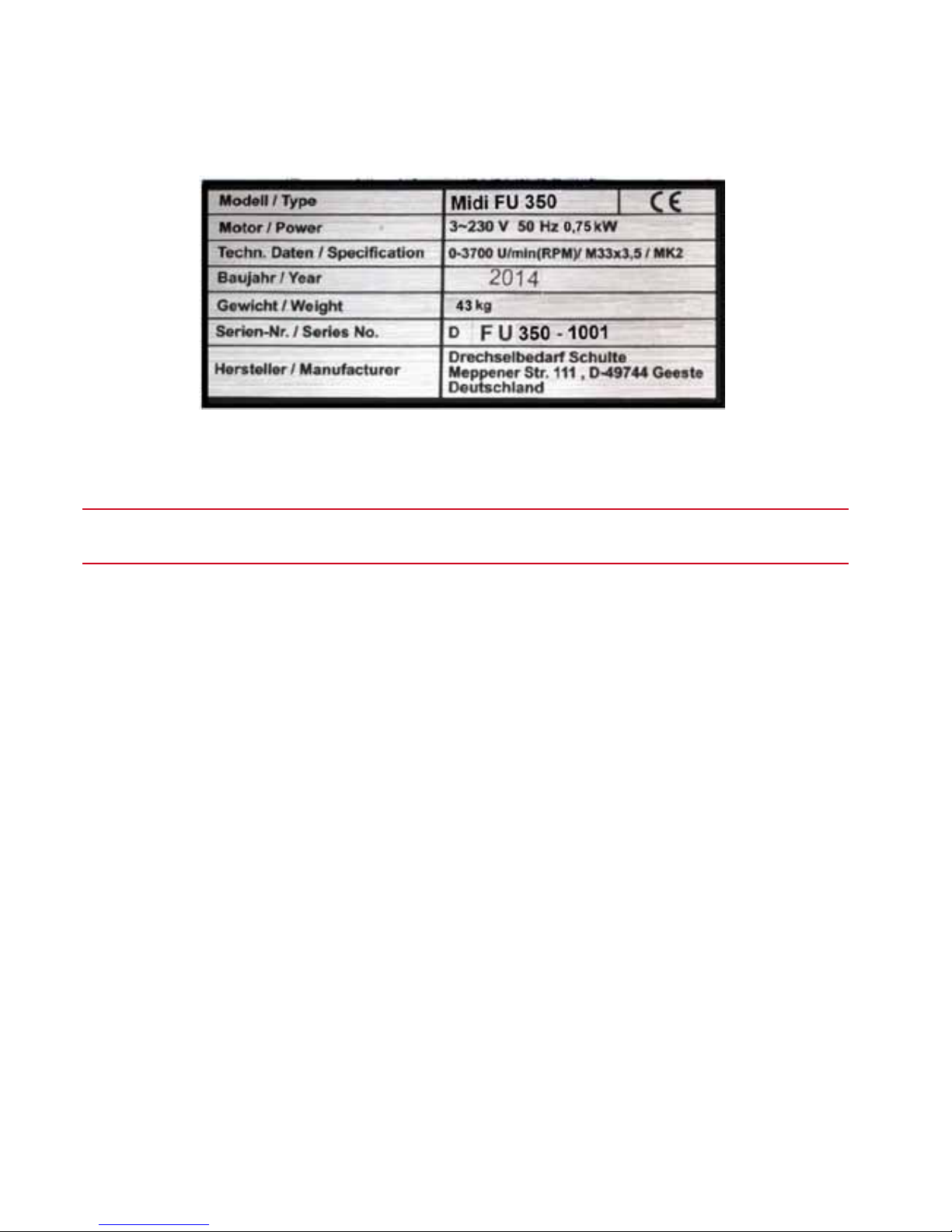
Nameplate
Fig. 1
4. Functional instructions
A Midi FU-350 lathe is a machine, that is generally used to edit cylindrical or prismatic timber workpieces.
Here, the workpieces with special xing between headstock and tailstock or using special jigs (chuck, face
plate, etc.) are clamped and driven by an electric motor.
The machine is driven by the electric motor via pulleys on the spindle. The Midi has three speed groups
(Translations) that you can choose. The ne tuning of the motor speed is done through a frequency conversion, which should be regulated over the potentiometer (short POTI) at the mobile control box so that you
can adjust the motor speed continuously in the respective group speed. This will help you to choose a reasonable peripheral speed according to the workpiece diameter. This improves the security when turning and
the quality of the workpiece surface.
To turn on the drive unit, rst connect the plug of the Midi in the operator’s existing grounded socket. Turn
on the motor on the mobile control box (Fig. 2) and adjust the motor speed slowly up on the potentiometer.
Automatic shutdown
The Midi is equipped with a zero-voltage switch, which switches off the bench during a power outage and prevents a restart if the power supply is restored. If overloaded, the speed can be switched off by the frequency
converter while turning. To be able to take the lathe back into operation in all cases, the cause must be eliminated. During a power failure the power supply shall be restored, when lifting the cover it shall be closed
again and when overloaded it shall be reduced or the pulley with the lower speed indication shall be chosen.
By means of the hand rest the turning chisel will be guided to the workpiece by hand, which entails a risk of
injury, since the cutting forces must be absorbed by the operator.
In order to derive the resultant forces, the turner knifes must continually lie rmly on the knife support.
It is important that you read the manual carefully prior to rst use to learn about the dangers which
might arise caused by the operation of the machine (in particular rotating parts, occurring forces or
danger of injury).
- 8 -
© Drechselbedarf SchulteOriginal Operating Instructions V1.0

If you do not have any previous experience with turning, inform yourself before rst start of the lathe. Please
consult turning specialists and knowledgeable people and be instructed.
At our company location, we offer courses for beginners and advanced courses.
Electronic frequency converter FU
The Delta frequency converter is programmed particularly quiet and ready for operation. Please do not make
any changes to the frequency converter itself. The knurled screw or programming screw on the rear of the FU
drive shall be operated only by qualied personnel. Speed changes to the lathe by the user or
turner may only be made via the potentiometer on the control box with the magnet at the bottom.
The FU is programmed with a soft start and soft stop. You can not shorten the phasing-out time after stopping
with the handwheel, let the workpiece simply phase out after stopping.
© Drechselbedarf Schulte Original Operating Instructions V1.0
- 9 -
5. Protection devices
Protection devices are used to protect people and property. Without intact protection devices it could lead to
serious injuries.
Danger!
Die Drechselmaschine darf nur mit funktionierenden Sicherheitseinrichtungen betrieben werden.
Schalten Sie die Drehmaschine sofort ab, wenn Sie feststellen, dass eine Sicherheitseinrichtung
fehlerhaft oder demontiert ist! Alle betreiberseitigen Zusatzanlagen müssen mit den vorgeschriebenen
The turning machine shall only be operated with functioning protection devices.
Turn off the lathe immediately if you notice that a protection device is defective or dismantled! All operators additional devices shall be equipped with the prescribed protective
devices.
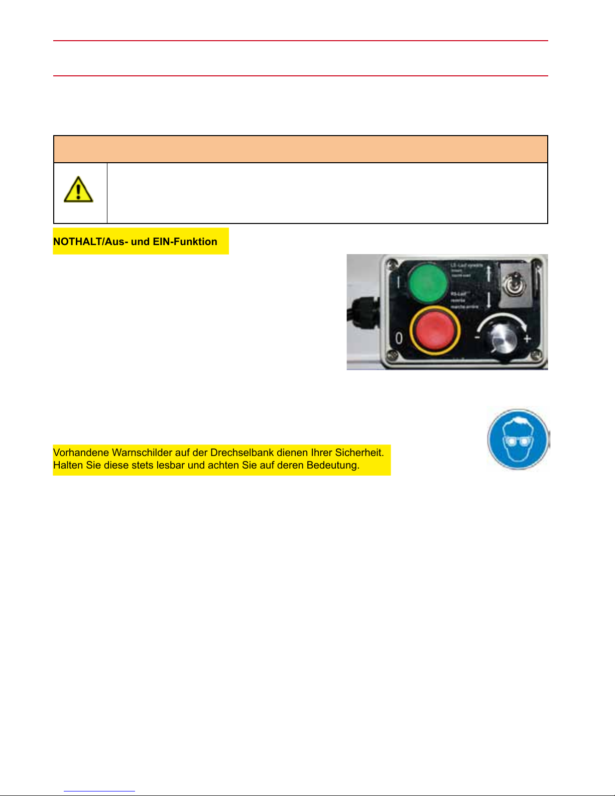
NOTHALT/Aus- und EIN-Funktion
The lathe has a red combination switch (0) on which it can be
turned off by the EMERGENCY STOP or switched off normal-
ly (Fig. 2). All machine functions will be stopped by pressing
the red button (0).
To restart, press the green button (I).
The toggle switch is used to turn on the revers rotation
(make sure that the discharge valve on the faceplate is operating).
Use the potentiometer to adjust the motor speed.
Warning labels on the lathe
Vorhandene Warnschilder auf der Drechselbank dienen Ihrer Sicherheit.
Halten Sie diese stets lesbar und achten Sie auf deren Bedeutung.
Wear safety goggles (see Figure 3)
Overview of further safety devices
The lathe has various safety devices:
1. Electrical protective conductor which is connected to the earthing-pin plug to the local power grid.
2. Cover over the drive pulley (can only be opened with tools).
3. Covers on the electric motor.
4. Emergency shut-down (located on the mobile control box).
5. Discharge valve of the faceplate through two hex/grub screws in reverse rotation
- 10 -
© Drechselbedarf SchulteOriginal Operating Instructions V1.0
Fig. 3
Fig. 2

6. Requirements for the set-up location
Requirement Recommendation
Set-up location of the lathe Place the Midi FU - 350 in a dry interior close to a power source (mains).
Watch out for at, rm and stable surface.
Allow sufcient space in front of the machine as a workspace.
Other established machines in the workshop shall not affect the operation of
the lathe.
Lighting and ventilation Make sure that there is a good light (illuminance levels according to DIN5035)
and ventilation. Additionally use an adjustable lighting system for your workspace on the lathe, so that no shadows will be thrown on the workpiece. We
recommend the establishment of a light source which worth at least 300 LUX,
better has a 500 LUX on the cutting edge.
If possible, place the machine near a window.
Electrical equipment A suitable standard household 230 V socket which is fused with 16 amp. is
required to operate the lathe.
Electrical cables and sockets must comply with local electrical regulations.
If in doubt, ask your professional electricians. Avoid the use of an extension
cord (see also the chapter « Connection of the lathe to the power supply»).
Ventilation Ventilate your workplace sufciently. The degree of ventilation depends on the
size of the workshop and the number of nished workpieces. The use of dust
extraction systems and lters reduce your health risk.
Working height The lathe should be located such that the spindle center position is at the
height of the operators elbow.
Working space Before the lathe shall be a free space of at least 80 cm.
Base unit Since the MIDI FU-350 is a benchtop, the operator has to ensure to use a pro-
per installation space or a suitable base unit. Your dealer offers a base unit.
The provided 3/8 «x 50 mm screws can be rmly connected to a base unit
instead of using the feet.
© Drechselbedarf Schulte Original Operating Instructions V1.0
- 11 -
7. Installation of the lathe
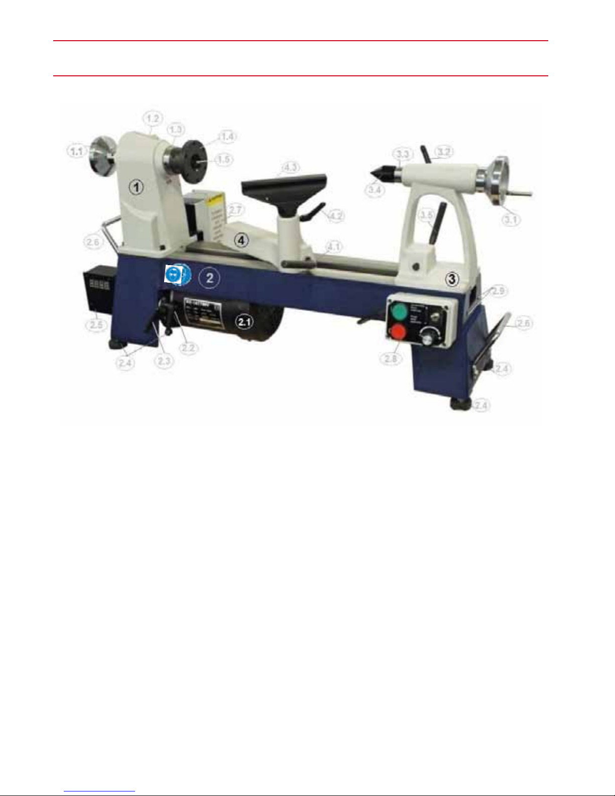
Description of the lathe
1 Headstock
1.1 Handwheel
1.2 Cover pulleys
1.3 Spindle with M33 thread,
1.4 Faceplate
1.5 Driver
2 Bench bed
2.1 Electric motor
2.2 Motor lock quick-release lever
2.3 Clamping lever motor
2.4 Rubber feet
2.5 Digital speed display
2.6 Carry handles
2.7 Frequency converter (FU)
2.8 Mobile control box
2.9 Drill holes for bed extension
3 Tailstock
3.1 Handwheel
3.2 Quick-release lever for quill lock
3.3 Quill with measuring scale
3.4 Revolving center punch
3.5 Lever tailstock
4 Bottom of hand rest
4.1 Clamping-lever hand rest
4.2 Quick-release lever hand-knife support
4.3 Hand-knife support
- 12 -
© Drechselbedarf SchulteOriginal Operating Instructions V1.0
7. Montage der Drechselbank
Fig. 4
 Loading...