

Page 1
UST25-4000HDi
v2
Page 2

Page 3

Page 4

Changes
Dreamvision provides this manual ‘as is’ without warranty of any kind, either expressed or implied, including but
not limited to the implied warranties or merchantability and fitness for a particular purpose. Dreamvision may
make improvements and/or changes to the product(s) and/or the program(s) described in this publication at any
time without notice.
This publication could contain technical inaccuracies or typographical errors. Changes are periodically made to
the information in this publication; these changes are incorporated in new editions of this publication.
Copyright
All right reserved. No part of this document may be copied, reproduced or translated. It shall not otherwise be
recorded, transmitted or stored in a retrieval system without the prior written consent of Dreamvision.
Guarantee
Dreamvision provides a guarantee relating to perfect manufacturing as part of the legally stipulated terms of
guarantee. On receipt, the purchaser must immediately inspect all delivered goods for damage incurred during
transport, as well as for material and manufacturing faults. Dreamvision must be informed immediately in writing
of any complaints. If the purchaser or third party caries out modifications or repairs on goods delivered by
Dreamvision, or if the goods are handle incorrectly, in particular if the systems are commissioned operated
incorrectly or if, after the transfer of risks, the goods are subject to influences not agreed upon in the contract, all
guarantee claims of the purchaser will be rendered invalid. Not included in the guarantee coverage are system
failures which are attributed to programs or special electronic circuitry provided by the purchaser, e.g. interfaces.
Normal wear as well as normal maintenance are not subject to the guarantee provided by Dreamvision either.
The environmental conditions as well as the servicing and maintenance regulations specified in this manual must
be complied with by the customer.
Trademarks
Brand and product names mentioned in this manual may be trademarks, registered trademarks or copyrights of
their respective holders. All brands and product names mentioned in this manual serve as comments or examples
and are not to be understood as advertising for the products of their manufactures.
2
R699855 - UST25-4000HDi User Manual
Page 5

TABLE OF CONTENTS
1.0 SAFETYINSTRUCTIONS .....................................................................................................4
1.1 Important Information ....................................................................................................................4
1.2 Laser Class 2 and Eye Safety .........................................................................................................4
1.3 Regional Specic Information........................................................................................................4
1.4 Important Safeguards .....................................................................................................................5
2.0 INSTALLATIONGUIDELINES ...........................................................................................6
2.1 Introduction ....................................................................................................................................6
2.2 Environment of Use........................................................................................................................6
2.3 Air-Flow and Space Requirements .................................................................................................7
2.4 Ceiling Mounting the Unit .............................................................................................................7
2.5 Projection Distance and screen Offset ............................................................................................7
3.0 REMOTECONTROLUNIT(RCU) ....................................................................................8
4.0 GETTINGSTARTED
4.1 General View ..................................................................................................................................9
4.2 Control Panel and Navigation Buttons .........................................................................................10
4.3 Picture Focus ................................................................................................................................ 11
4.4 Picture Level and Tilt setting........................................................................................................11
5.0 CONNECTIONS .....................................................................................................................11
5.1 Caution when connecting a Device to HDMI Input ..................................................................... 11
5.2 Connecting a Video Source to the Projector.................................................................................12
5.3 Connecting an Automation or Control device ..............................................................................13
5.4 Connecting the Power Cord .........................................................................................................13
5.5 First Power On / Off .....................................................................................................................13
5.6 Accessing Multimedia Files .........................................................................................................14
6.0 MENUSTRUCTURE ............................................................................................................ 15
7.0 MENUS
7.1 Picture ...........................................................................................................................................16
7.2 Screen ...........................................................................................................................................17
7.3 Setting ...........................................................................................................................................18
7.4 Volume .......................................................................................................................................... 18
7.5 Options .........................................................................................................................................19
7.6 3D .................................................................................................................................................19
7.7 Interactive function.......................................................................................................................20
7.8 LAN ..............................................................................................................................................20
..................................................................................................................................... 16
8.0 3DCONTENTAND3DPROJECTION ........................................................................... 20
8.1 General Information about 3D playback ......................................................................................20
8.2 Projector 3D Settings....................................................................................................................20
9.0 MAINTENANCE ................................................................................................................... 21
9.1 Cleaning and Replacing the Dust Filters ......................................................................................21
9.2 Dirt on the Projector beam window .............................................................................................21
9.3 Troubleshooting ............................................................................................................................22
10.0 MISCELLANEOUS ............................................................................................................... 22
10.1 Control via the Web Interface .......................................................................................................22
10.2 RS-232C protocol ......................................................................................................................... 23
10.3 Specications................................................................................................................................26
..............................................................................................................9
R699855 - UST25-4000HDi User Manual 3
Page 6
SAFETY INSTRUCTIONS
1.0 SAFETY INSTRUCTIONS
1.1 Important Information
Lead-free regulation
This product contains lead in some components. Disposal of these materials may be regulated in your community
due to environmental considerations. For disposal or recycling information please contact your local authorities,
or the Electronics Industries Alliance: http://www.eiae.org.
Information for Users on Disposal of Old Equipment
This symbol indicates that the electrical and electronic equipment should not be disposed as general
household waste at its end of life. Instead, the product should be handed over to the applicable
collection point for the recycling of electrical and electronic equipment for proper treatment, recovery
and recycling in accordance with your national legislation.
By disposing of this product correctly, you will help to conserve natural resources and will help
prevent potential negative effects on the environment and human health which could otherwise be caused by
inappropriate waste handling of this product.
For more information about collection point and recycling of this product, please contact your local municipal
office, your household waste disposal service or the shop where you purchased the product. Penalties may be
applicable for incorrect disposal of this waste, in accordance with national legislation.
1.2 Laser Class 2 and Eye Safety
This projector is a Class 2 laser device that conforms with IEC 60825-1:2007 and CFR 1040.10 and
1040.11. DO NOT STARE INTO THE BEAM
• This projector has built-in Class 4 laser module. Disassembly or modification is very dangerous and should
never be attempted.
• Any operation or adjustment not specifically instructed in this user manual creates the risk of hazardous laser
radiation exposure.
• Do not open or disassemble the projector as this may cause damage by the exposure of laser radiation.
• Never stare into beam when the projector is on.
• Without following the control, adjustment or operation procedure may cause damage by the exposure of laser
radiation.
• Adequate instructions for assembly, operation, and maintenance, including clear warnings concerning
precautions to avoid possible exposure to laser and collateral radiation in excess of the accessible emission
limits in Class 2.
. The bright light may result in permanent eye damage.
1.3 RegionalSpecicInformation
CE mark and Directive 2011/65/EU - ROHS 2 (Europe only)
In accordance with Article 7 and the adoption into national law by 2nd January 2013, this product has been
designed and manufactured in accordance with Article 4. The technical documentation and the written declaration
of conformity that assesses the product conformity can be provided to the competent National Authority upon an
email request to: rohs2@dreamvision.net
Other Countries outside the European Union:
If you wish to dispose of this product, please do so in accordance with applicable national legislation or other rules
in your country for the treatment of old electrical and electronic equipment.
About the installation place
Do not install the projector in a place that cannot support its weight securely. If the installation place is not sturdy
enough, the projector could fall or overturn, possibly causing personal injury.
To reduce the risk of electric shock, do not remove cover. Refer servicing to qualified service personnel.
This projector is equipped with a 3-blade grounding type plug to satisfy FCC rule. If you are unable to
4
R699855 - UST25-4000HDi User Manual
Page 7
SAFETY INSTRUCTIONS
insert the plug into the outlet, contact your electrician.
To prevent fire or shock hazards, do not expose this appliance to rain or moisture. This apparatus must
be earthed.
1.4 Important Safeguards
Electrical energy can perform many useful functions. This unit has been engineered and manufactured to
assure your personal safety. IMPROPER USE CAN RESULT IN POTENTIAL ELECTRICAL SHOCK OR FIRE
HAZARD. In order not to defeat the safeguards incorporated into this product, observe the following basic rules
for its installation, use and service.
The power input is auto-ranging from 100 to 240 VAC.
Please read these Important Safeguards carefully before use.
• All the safety and operating instructions should be read before the product is operated.
• Place the projector near a wall outlet where the plug can be easily unplugged.
• Unplug this product from the wall outlet before cleaning. Do not use liquid cleaners or aerosol cleaners. Use
a damp cloth for cleaning.
• Do not use attachments not recommended by the product manufacturer as they may be hazardous.
• Do not use this product near water. Do not use immediately after moving from a low temperature to high
temperature, as this causes condensation, which may result in fire, electric shock, or other hazards.
• Do not place this product on an unstable cart, stand, or table. The product may fall, causing serious injury
to a child or adult, and serious damage to the product. The product should be mounted according to the
manufacturer’s instructions, and should use a mount recommended by the manufacturer.
• When the product is used on a cart, care should be taken to avoid quick stops, excessive force, and uneven
surfaces which may cause the product and cart to overturn, damaging equipment or causing possible injury
to the operator.
Slots and openings are provided for ventilation must not be blocked or covered. Do not place this unit on
a bed, sofa, rug or other similar surface.
• This product should be operated only with the type of power source indicated on the label. If you are not sure
of the type of power supply to your home, consult your product dealer or local power company.
• This product is equipped with a three-wire plug. This plug will fit only into a grounded power outlet. If you are
unable to insert the plug into the outlet, contact your electrician to install the proper outlet. Do not defeat the
safety purpose of the grounded plug.
• Power-supply cords should be routed so that they are not likely to be walked on or pinched by items placed
upon or against them. Pay particular attention to cords at doors, plugs, receptacles, and the point where they
exit from the product.
• For added protection of this product during a lightning storm, or when it is left unattended and unused for long
periods of time, unplug it from the wall outlet and disconnect the cable system. This will prevent damage to the
product due to lightning and power line surges.
• Do not overload wall outlets, extension cords, or convenience receptacles on other equipment as this can
result in a risk of fire or electric shock.
• Never push objects of any kind into this product through openings as they may touch dangerous voltage points
or short out parts that could result in a fire or electric shock. Never spill liquid of any kind on the product.
• Do not attempt to service this product yourself as opening or removing covers may expose you to dangerous
voltages and other hazards. Refer all service to qualified service personnel.
• Unplug this product from the wall outlet and refer service to qualified service personnel under the following
conditions:
a) When the power supply cord or plug is damaged.
b) If liquid has been spilled, or objects have fallen on the product.
c) If the product has been exposed to rain or water.
d) If the product does not operate normally by following the operating instructions. Adjust only those controls
that are covered by the Operation Manual, as an improper adjustment of controls may result in damage and
will often require extensive work by a qualified technician to restore the product to normal operation.
e) If the product has been dropped or damaged in any way.
f) When the product exhibits a distinct change in performance - this indicates a need for service.
• When replacement parts are required, be sure the service technician has used replacement parts specified
R699855 - UST25-4000HDi User Manual 5
Page 8
INSTALLATION GUIDELINES
by the manufacturer or with same characteristics as the original part. Unauthorized substitutions may result in
fire, electric shock, or other hazards.
• Upon completion of any service or repairs to this product, ask the service technician to perform safety checks
to determine that the product is in proper operating condition.
• The product should be placed more than one foot away from heat sources such as radiators, heat registers,
stoves, and other products (including amplifiers) that produce heat.
• When connecting other products such as VCR’s, and personal computers, you should turn off the power of
this product for protection against electric shock.
• Do not place combustible behind the cooling fan. For example, cloth, paper, matches, aerosol cans or gas
lighters that present special hazards when over heated.
• When it is used by other power supply voltage, power cable must be changed. Ensure that the power cable
used for the projector is the correct type for the AC outlet in your country. Consult your product dealer.
• Caution: Do not allow any unqualified person to install the unit. Be sure to ask your dealer to install the unit
(e.g. attaching it to the ceiling) since special technical knowledge and skills are required for installation. If
installation is performed by an unqualified person, it may cause personal injury or electrical shock.
2.0 INSTALLATION GUIDELINES
2.1 Introduction
This product is powered by a Laser Solid State Light (Laser SSL) source and uses a single DLP chip to produce
a Full-HD picture.
Supported 2D signals
480i/p60, 576i/p50, 720p@50/60, 1080i/p@50/60, 1080p/24 and computer signal from VGA (640x480@60Hz)
up to UXGA (1600x1200@60Hz).
Supported 3D signals
This unit is compatible with 3D playback. The source can be connected using one of the two available HDMI
inputs. This unit is compatible with the following 3D formats:
• 1080p @ 23.98/24Hz - Frame Packing, Top & Bottom and Side-by-Side.
• 720p @ 50 or 59.94/60Hz - Frame Packing, Top & Bottom and Side-by-Side.
• 1080i @ 50 or 59.94/60Hz - Top & Bottom and Side-by-Side.
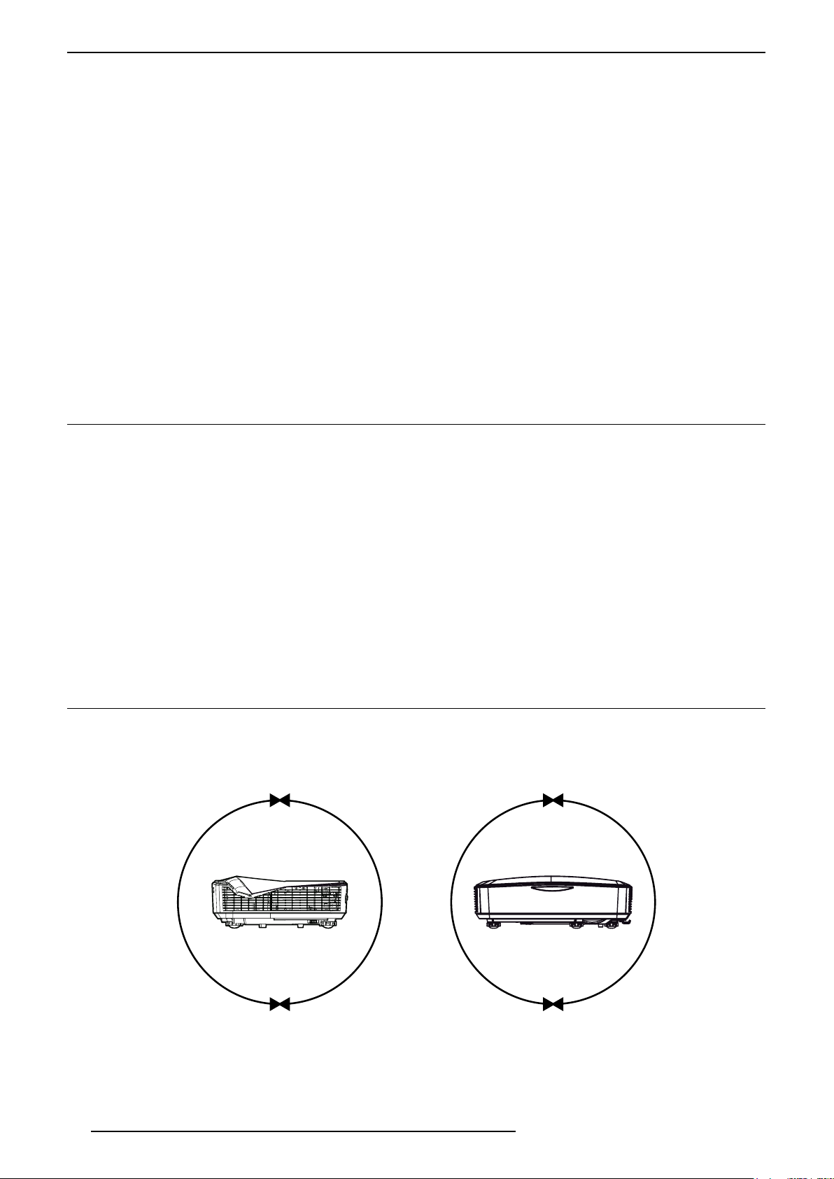
2.2 Environment of Use
This unit makes use of a LASER light source that can reaches a high temperature during projection. Do not allow
projection under the following conditions:
• Projection at a location that blocks the air inlets or exhaust vents.
• Projection at a place exposed to the hot air blast from an air conditioner.
This unit can be operated on any side and can project both landscape or portrait pictures
6
R699855 - UST25-4000HDi User Manual
Page 9
INSTALLATION GUIDELINES
A
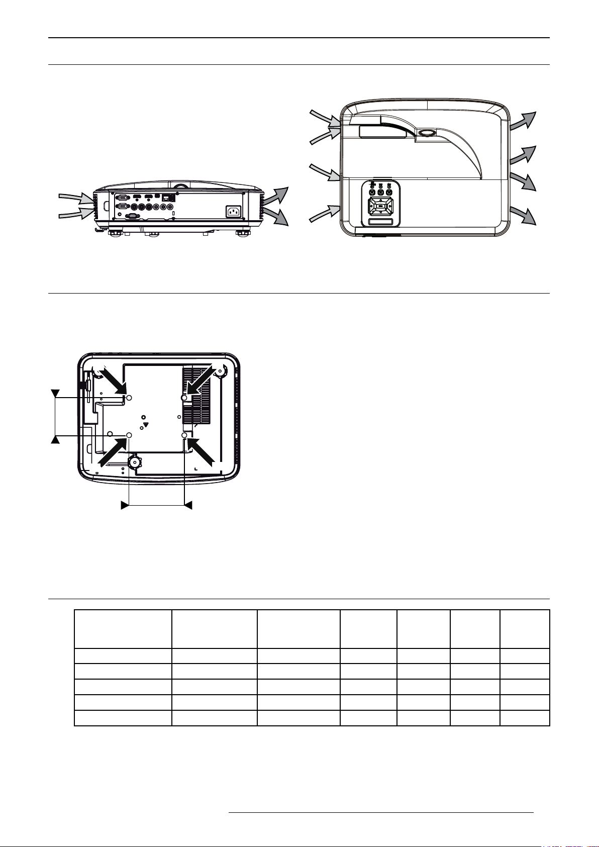
2.3 Air-Flow and Space Requirements
Make sure that the unit is installed with at least 20cm of non-obstructed space on each side to allow a sufficient
air flow to the air inlets (A) and from the air outlets (B).
A
B
B
A
B
A
Air ow: air inlets (A) and air outlets (B)
2.4 Ceiling Mounting the Unit
When mounting of this unit is required, make use of four M4x4 screws at the bottom of this unit indicated by the
letter A. Keep at least 10 cm space gap between the bottom of this unit and the ceiling to allow sufficient air flow.
Precautions for Ceiling-mount
A
d
A
A
A
• To ceiling-mount this unit, special expertise and techniques are
necessary. Be sure to ask a specialist to perform mounting.
• Do not mount at places that may be subjected to vibrations.
• Depth of the mounting holes (A) is 12 mm. Use screws that would
insert at least 10mm into the mounting holes. Avoid too long screws as
they may damage inside this unit.
• Regardless whether the unit is still under guarantee, Dreamvision
is not liable for any product damage caused by mounting the unit with
third party ceiling mount or when the environment is not suitable for
ceiling-mount.
B
B
D
Dimensions
• Distances between left and right holes is D = 130 mm.
• Distances between front and back holes is d = 88 mm.
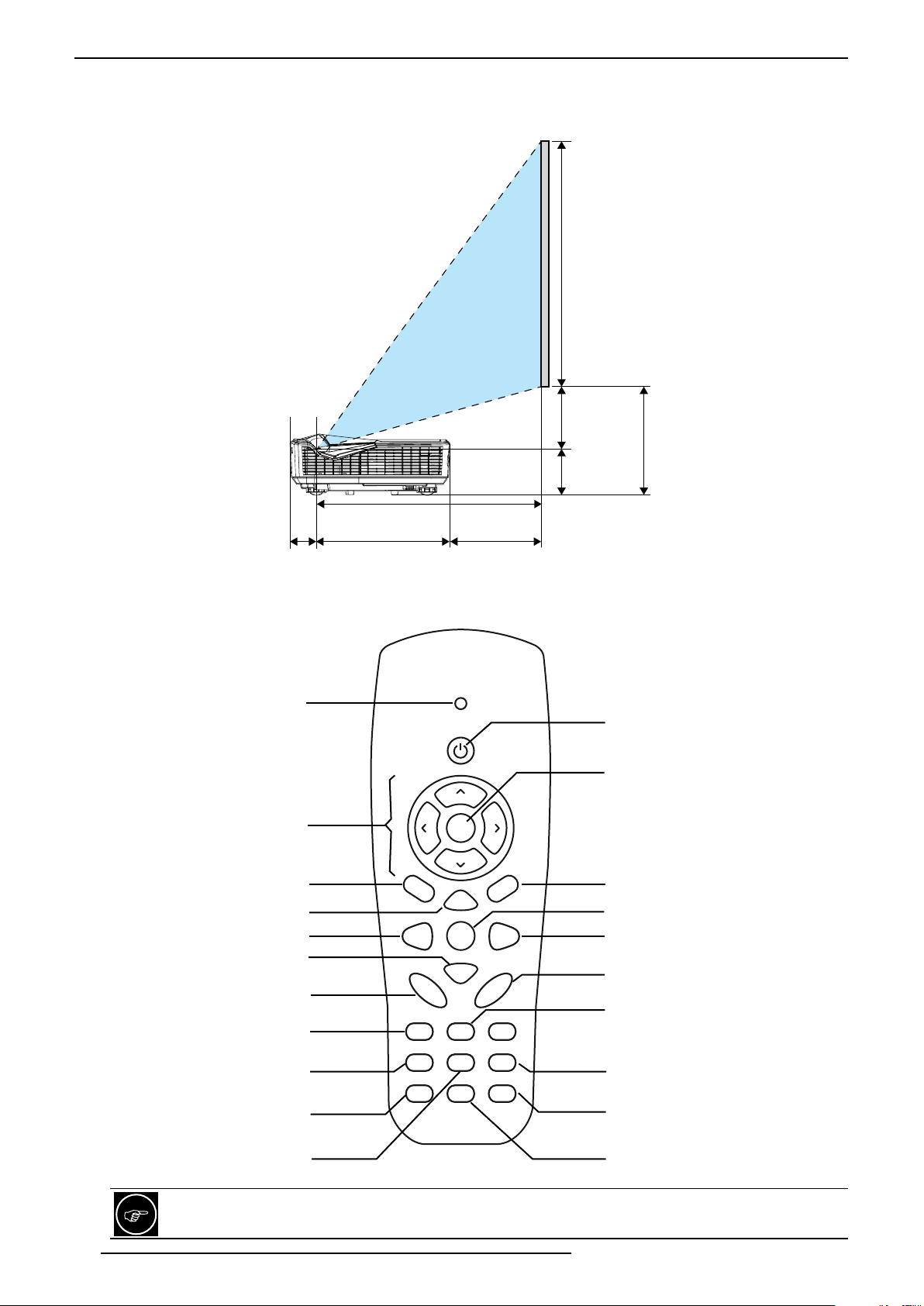
2.5 Projection Distance and screen Offset
Projection Screen
Diagonal Size
(Aspect Ratio 16:9)
75” (190 cm) 65.4” (166 cm) 36.8” (93.5 cm) 41 cm 17 cm 19 cm 26 cm
80” (203 cm) 69.7” (177 cm) 39.2” (100 cm) 44 cm 20 cm 20 cm 27 cm
90” (228 cm) 78.4” (199 cm) 44.1” (112 cm) 49 cm 25 cm 22 cm 22 cm
100” (254 cm) 87.2” (221 cm) 49.0” (125 cm) 54 cm 30 cm 25 cm 32 cm
110” (279 cm) 95.9” (243 cm) 53.9” (137 cm) 60 cm 36 cm 27 cm 35 cm
• The projection screen sizes and projecting distances in the table above are provided only as a guide. Please
use them as reference during installation.
• The distances are calculated for a projection image of 16:9 aspect ratio
• The Throw Ratio is 0.25:1, calculated from the projection distance D1, this distance is the distance between
the projection beam window and the screen. You can use distance D2 between the projector and the wall
Projection
Screen
Base Size
Projection
Screen
Height H
Proj.
DistanceD1DistanceD2Offset
O1
Offset
O2
R699855 - UST25-4000HDi User Manual 7
Page 10
REMOTE CONTROL UNIT (RCU)
instead of D1 if needed.
• The screen offset fixed to 70%, that means that O1 is equal to 20% of the total height of the screen. You can
use O2 instead of O1 if needed, O2 is the distance from the bottom of the projector to the bottom of the screen.
H : Screen Height
O1: 20%
O2: Offset from the bottom
75 mm
D1: projection distance
70 mm
240 mm D2’: projection distance from the projector
3.0 REMOTE CONTROL UNIT (RCU)
LED indicator
Power button
Confirm button
[Exit] Menu
[Reset] to default settings
[Input] selection
[Volume] setting
Select [Image] profile
Change [Aspect] ratio
Select [HDMI 1] input
Directionnal keys
Display [Menu]
Zoom in [+]
Input selection [Auto]
Zoom out [-]
[Keystone] setting
Switch momentarily the
picture to a [Blank] screen
Select [VGA 1] input
Keystone
Power
Enter
ExitMenu
Zoom+
Reset InputAuto
Volume
Zoom-
++
-
-
AspectImageBlank
HDMI1FreezeVGA1
HDMI2VideoVGA2
Select [VGA 2] input
[Freeze] screen
press again to resume
Select [HDMI 2] input
Select Composite [Video]
input
The remote control unit can be used by having the signal reflected off a screen, as the effect of signals
reflected differs with the type of screen used, operable distance may decrease.
8
R699855 - UST25-4000HDi User Manual
Page 11

GETTING STARTED
If the remote control has to be brought closer to the projector to operate, it means that the batteries are
wearing out. When this happens, replace the batteries.
Button Description
LED indicator Lights up when a command is sent from the RCU.
Power Press to turn ON or OFF this unit.
Enter To select or to confirm action.
Directional keys To navigate into On Screen Display (OSD) Menu.
Menu Press this button launch the On Screen Display (OSD) [Menu].
Exit Press to close the OSD Menu.
Zoom + / - Sets the digital [Zoom] value from 0 to 20.
Reset [Reset] the current setting to default value.
Input To switch [Input] source.
Auto Switches [Auto]matically to a valid input.
Keystone + / - Sets the [Keystone] value from 0 to 20.
Volume + / - Sets the [Volume] output from 0 to 30.
Blank Switches momentarily the picture to a [Blank] screen.
Image Sets the current [Image] profile to Bright, PC, Movie, Game or User profile.
Aspect Changes the picture [Aspect] Ratio.
Freeze [Freeze] the projection to the wcurrent displayed image. Press again to resume.
VGA 1/2 / HDMI 1 /2, Video Selects [VGA 1/2, HDMI 1/2, Video] as the active input.
4.0 GETTING STARTED
4.1 General View
Top side
Projector beam window
Operating LEDs
Control Panel and
Navigation buttons
(*) Optional
interactive camera
Top-side Infrared receiver
• Projector beam window: the picture is projected from this glass, keep this area clean to obtain a good picture.
• Operating LEDs display the unit status. If an error occurs, please refer to “9.3 Troubleshooting”, page 22
• Control panel and Navigation buttons. Refer to “4.2 Control Panel and Navigation Buttons”, page 10 for
more information.
• Top-side Infrared receiver, point the RCU to this area to optimize its functions.
• (*) Optional touch camera: the camera is only available on the interactive models.
R699855 - UST25-4000HDi User Manual 9
Page 12

GETTING STARTED
Front-side Infrared receiver
Level-adjustment feet
Inputs Panel
Front side
• Front Infrared receiver, point the RCU to this area to optimize its functions.
• Level-adjustment feet to adjust and set the correct picture level and tilt.
• Focus tab to set the picture sharpness manually.
Rear side
Focus tab
Main Power socket
Input connections and Main Power input socket
• Input Panel: connect your video source to the correct input.
• Main Power socket: connect the power cord as shown below.
• Kesington lock to secure this unit in an openned or public place.
4.2 Control Panel and Navigation Buttons
Operating LEDs
Power button
[Menu] button
[Input] button
Directional keys
and [Enter] button
Infrared receptor
ON/
STANDBY
TEMP
MENU INPUT
Enter
LAMP
Kesington lock
Operating LEDs ON/Standby LED indicates the status of this unit.
Power button Press to turn ON or OFF this unit.
Menu button Press this button launch the On Screen Display (OSD) Menu. Press again to exit
Input source To switch input source.
[Enter] button To select or to confirm action.
Directional keys To navigate into On Screen Display (OSD) Menu.
Infrared receptor Receives infrared commands from the Remote Control Unit (RCU).
10
Button Description
LAMP LED indicates the status of the light source.
TEMP LED refer to this unit temperature status.
Menu.
R699855 - UST25-4000HDi User Manual
Page 13

4.3 Picture Focus
The picture focus can be set manually using the Focus Tab located on the side of this unit.
Slide the focus tab to obtain a sharp picture.
4.4 Picture Level and Tilt setting
The picture level and tilt should be obtained by setting the Level-ajustment feet.
a) Locate the adjustable foot you wish to modify on the underside of the projector.
b) Rotate the adjustable ring clockwise to raise the projector or counter clockwise to lower it. Repeat with the
remaining feet as needed to obtain a perfectly level picture.
CONNECTIONS
Focus tab
Elevating feet
Rotate the feet to adjust the picture level and tilt.
5.0 CONNECTIONS
5.1 Caution when connecting a Device to HDMI Input
Prior to connecting any device to this unit, switch the projector in standby mode. Never connect a HDMI
source to this unit when the projector is in operate mode. The HDMI termination is a self-powered
R699855 - UST25-4000HDi User Manual 11
Page 14

CONNECTIONS
HDMI 2
connection and can cause electric discharges.
5.2 Connecting a Video Source to the Projector
HDMI 1
VGA 1 or
Component YPbPr
WiFi Dongle
USB Disk or Key
VGA 2
Microphone
Yellow Video
Red Audio R
White Audio L
Audio/Video Connection Device to connect
HDMI 1
HDMI 2 / MHL
(with audio, DVI compatible)
VGA 1
VGA 2 In
WiFi dongle / USB Disk The USB input accepts the WiFi dongle to enable the wireless communication
Microphone Connect a microphone to this input.
Audio In Connect to this input the coresponding audio to VGA video input. The Audio In
HDMI or DVI-D sources: Blu-ray Disc player, DVD-player equipped with HDMI
output, Game Console, Computer with DVI-D output.
NB: HDMI 2 input supports MHL protocol.
VGA or Sub-D15 sources such as computers, game consoles or video boxes with
computer resolutions.
between your source and this unit or any USB Disks and USB Keys. Select the
Multimedia Input for WiFi to read multimedia files from the USB input.
input uses a stereo jack 3.5mm.
Audio IN
12
R699855 - UST25-4000HDi User Manual
Page 15

5.3 Connecting an Automation or Control device
CONNECTIONS
RS-232C
for Automation
Connection Device to connect
RS-232 C Automation Device, Control Device or Computer with RS-232 capability.
LAN Connect to rooter or Computer with RJ-45. Control this unit using the Crestron
web interface.
CONNECTING AN AUTOMATION/CONTROL DEVICE
This unit can control or be controlled by using several input/output terminals. Each terminal is ruled by
specific protocols. Please refer to Appendix for more information.
5.4 Connecting the Power Cord
•Before plugging in the power cord, ensure that all devices have been connected to their
respective inputs of this unit.
•Connect the power cord to the power input terminal of the projector.
LAN to rooter
for C control
5.5 First Power On / Off
Power On
Prior the first power on, make sure that the power cord is firmly inserted into the Power socket and that your video
and audio sources are connected correctly to the corresponding inputs located at the rear side of this unit.
Then press the Power button on the control panel on the Top side of the projector or on the Remote Control Unit
(RCU) and wait 8 seconds for the projector to light up and to display the startup screen.
• If you have only one source connected, the projector will detect the source automatically. If not, go into the
menu and browse to the Options and set Off the “Source Lock” option.
• If you have several inputs connected, press the Input button to select the desired source.
Power Off
Press the Power button on the Control Panel or the RCU, and press it twice to confirm and to power Off this unit.
R699855 - UST25-4000HDi User Manual 13
Page 16

CONNECTIONS
5.6 Accessing Multimedia Files
This projector supports two methods to read media files (photos, videos, music, documents), they can be stored;
a) Wirelessly, the projector accesses the media files stored on your mobile phone, tablet PC, notebook, or
desktop using the WLAN. This requires the WiFi dongle to be connected to the WiFi/USB port of this unit.
b) Files stored on a USB key or disk drive, the USB key or disk must be connected to the USB port.
Selecting the Multimedia input
Press on the RCU or on the Control panel the Input button and use the directionnal keys to highlight Multimedia
and press Enter to confirm.
Depending on the location where the file is located, select one device between: Mobile/Tablet, Laptop, Desktop,
or USB Disk.
Follow the instructions at the screen on how to download and install EZView. EZView software is required when
a file is stored on a Mobile/Tablet, Laptop or Desktop.
Follow the instruction to install EZView software.
Multimedia Settings and Options
• System: Select this option to view the firmware version or to update firmware.
• Video: Select this option to change the aspect ratio and/or to set the repeat mode.
• Photo: Select this option to change the aspect ratio, slideshow pattern, and/or the slideshow speed.
• Music: Select this option to set the repeat mode.
• WiFi: Select this option to configure the Wi-Fi connection.
14
R699855 - UST25-4000HDi User Manual
Page 17

MENU STRUCTURE
6.0 MENU STRUCTURE
MAIN MENU SUBMENU AVAILABLE OPTIONS
Picture Color Mode (Ambiant light projection) Bright
(Computer pictures or digital photos) PC
(Movies or animes) Movie
(Video games) Game
(predefined Gamma) Blending
User
Wall Color White
Light Yellow
Light Blue
Pink
Dark Green
Brightness 0 - 100
Contrast 0 - 100
Sharpness 0 - 31
Saturation 0 - 100
Hue 0 - 100
Gamma 0 - 5
Color Temp 0 - 5
Color Settings Color: R, G, B, Cyan, Magenta, Yellow
Hue -99 to 100
Saturation 0 - 199
Gain 0 - 199
Screen Aspect Ratio Auto
4:3
16:9
16:10
Phase 0 - 31
Clock 0 - 20
H. Position adjust
V. Position adjust
Digital Zoom 0 - 10
V. Keystone -40 to 40
Orientationt Front
Front Ceiling
Rear
Rear Ceiling
Setting Language Choose one of the 18 languages
Menu location Select position
Closed Caption (NTSC only) Off / CC1 / CC2 / CC3 / CC4
VGA Out On / Off
LAN On / Off
VGA 2 (Function) Input / Output
Test Pattern On / Off
Reset Confirm
Volume Speaker On / Off
Line Out On / Off
Microphone On / Off
Mute On / Off
Volume 0 - 30
Microphone Volume 0 - 30
R699855 - UST25-4000HDi User Manual 15
Page 18

MENUS
Options Logo Default / User
Logo Capture Confirm
Auto Source On / Off
Input VGA-A
VGA-B
HDMI 1
Input HDMI 2
Composite
Multimedia
Auto Power Off (min) 10, 20, 30, 40
LASER Settings LASER Hours Used (Normal) (in min)
LASER Hours Used (Eco) (in min)
LASER Power Mode Normal / Eco
Clear LASER Hours Confirm
High Altitude On / Off
Filter Remind (hour) Set the filter reminder time (in hours) 1 - 20
Reset the reminder time Confirm
Information Display on screen Model name
SNID
Source Resolution
Software Version
Aspect Ratio
3D Enable 3D Auto, On, Off
3D Invert On / Off
3D Format Frame Packing
Side-by-side
Top and Bottom
Frame Sequential
Field Sequential
1080@24 Syncro 144Hz / 96Hz
Interactive Interactive Settings
HDMI or VGA inputs only, no 3D
Multimedia Status Display the current network connection status
DHCP On / Off
IP Address, Subnet, Gateway, DNS, MAC Address, Group Name, Projector Name,
Location, Contact
On / Off
7.0 MENUS
7.1 Picture
Color Mode
The factory preset Color Modes are available and they can be applied to any input. Use the < and > directional
keys to select the correct Color Mode between: Bright, PC, Movie, Game, Blending or User.
The User setting should be used to memorize specific picture settings that would not be covered by any
of the factory presets.
Wall Color
This setting compensates the color balance derived from the reflective characteristics of the wall in the case that
it is used as projection surface. You may select the best template corresponding to your wall color between the
available options: White, Light Yellow, Light Blue, Pink and Dark Green.
Choose White setting if you are using a projection screen.
16
R699855 - UST25-4000HDi User Manual
Page 19

MENUS
Brightness
The brightness function is used to adjust the overall light output. Adjust the Brightness value between 0 and 100.
Contrast
The contrast function is used to adjust the contrast between the light and dark areas of the displayed image. A
correct contrast setting is important for good image reproduction. Adjust the Contrast value between 0 and 100.
Sharpness
This function is used to adjust the image sharpness of the picture. Adjust the Sharpness value between 0 (soft)
and 30 (sharper).
Saturation
The Saturation function is used to adjust the quantity of colors in the picture from black and white to fully saturated.
Adjust the saturation value between 0 and 100.
Hue
The hue function is used to adjust the color tint to obtain true color reproduction. Adjust the Tint value between
0 (more green) and 100 (more red).
Gamma
Gamma is the relationship between the color values of the data and the color values displayed. The Gamma
presets adjust the brightness of the midtones without affecting the overall picture brightness. The Gamma setting
can be set to:
• 0: neutral Gamma curve
• 1: suits Blu-Ray movies and Full HD program using REC709 color space.
• 2: suits computer images or movies encoded in REC2020 color space.
• 3: suits projection in brighter environments.
Color Temp
Choose the correct color temp between 0 and 5.
Color Settings
The color settings allow a fine adjustment of the color gamut on six colors axis. Each color can be adjusted
individually: hue, saturation and gain. Possible color choices: Red, Green, Blue, Cyan, Magenta and Yellow.
7.2 Screen
Aspect Ratio
When watching a movie or video program, you can manually set the desired aspect ratio to fill your screen. Select
the correct aspect ratio depending on your source:
a) Auto. This setting keeps the image original width/height ratio and maximizes it to fill either the screen height
or the screen width which ever happens first.
b) 4:3. The original source is considered and scaled to fit 4:3 format on screen. Generally SDTV broadcasts.
c) 16:9. The picture size is 16:9, generally most recent DVDs, Blu-Ray discs or HDTV broadcasts.
d) 16:10. The image will be scaled to fit the width of the screen and the height adjusted to display the image
using a 16:10 ratio.
Phase
If the image appears to be unstable or to flicker, this function is used to synchronize the signal timing of the source
for a correct display.
Clock
Adjust to achieve an optimal image when there is a vertical flicker in the image.
H. Position and V. Position
Depending on your source, you may find that the picture should be adjusted into the screen, adjust the horizontal
and vertical position of the picture into the screen. Some signals may not be fully displayed, adjust this setting
properly when necessary by using < or > directional keys.
R699855 - UST25-4000HDi User Manual 17
Page 20

MENUS
Digital Zoom
Use the Digital Zoom to magnify or reduce the size of the picture at the screen. When feasable, avoid digital zoom
and set preferably the projector distance to the screen to increase or decrease the picture size.
V. Keystone
Compensate for trapezoidal distortion caused by installation. Independently to the screen orientation, make
sure that the projector is installed perpendically to the projection surface to reduce the use of Keystone. When
feasable, adjust the elevating feet to obtain a perfectly leveled unit to avoid the use of digital Keystone correction.
Ceiling Mount (Installation Style)
Flip the image to the left or right, up or down according to the projection state of the projector: Front, Ceiling
Mount, Rear or Rear Ceiling mount.
7.3 Setting
Language
Choose the OSD language between: English, Polish, German, Korean, Swedish, Russian, French, Spanish,
Arabic, Chinese Dutch, Italian, Norwegian, Portuguese, Danish, Turkish, Simplified Chinese and Japanese.
Closed Caption
Use this function to enable closed caption menu. Select an appropriate closed captions option: Off, CC1, CC2,
CC3, and CC4.
VGA Output
Activates the VGA connector.
LAN
Activates the RJ-45 port and enable the LAN connections.
VGA 2 (Function)
Select the VGA 2 function as an input or as an output. Setting the VGA 2 as a video output that can be useful to
easily monitor what is displayed on the screen from a front seat position.
Test Pattern
If set to On to display an internal pattern that can be useful during the first install or tests.
Reset
Use this function to return all parameters of all menus to their default factory settings.
7.4 Volume
Speaker
Use this function to activate or not the internal speakers.
Line Out
Use this function to activate or not the Audio Out (Jack) connector output.
Microphone
Use this function to activate or not the Microphone line input.
Mute
Use this function to turn the volume to 0 (no sound).
Volume
Set the desired volume level for the speakers or the Audio Out (Jack) between 0 and 30.
18
R699855 - UST25-4000HDi User Manual
Page 21

Microphone Volume
Set the desired volume level for the Microphone input. The Microphone is mixed together with the selected audio
input. Set the Microphone volume between 0 and 30.
7.5 Options
Logo
Use this function to set the desired startup screen. Select Default to set the startup screen to the factory default
or set User to upload your own logo using the “Capture Logo” menu.
The changes will take effect after a restart of the unit.
Logo Capture
Press > directional key to capture the current displayed image and set it as a User logo.
Auto Source
This function enables the automatic search for a valid signal on the inputs if the current input signal is lost. If set
to Off, the unit will wait until a valid signal is fed to the current selected input.
Input
Press the > directional key to display the Input selection popup menu. This unit will search only for inputs that are
selected by a tick. Enable or disable the desired input sources.
MENUS
Auto Power Off (Min)
After setting the countdown timer interval. The timer will start when there is no signal being sent to the projector.
The projector will automatically power off when the countdown (in minutes) has finished.
Laser Settings
•Laser Hours Used (Normal)
Display the projection time spent in normal mode.
•Laser Hours Used (ECO)
Display the projection time spent in ECO mode.
•Laser Power Mode
Set the power used by the LASER light source. Choose between Normal mode or ECO mode. The ECO
mode dims the projector light output which lowers power consumption and extends the life time of the
Laser SSL unit.
•Clear Laser Hours
Confirm to reset the laser hour counter.
High Altitude
Select this when the projector is in a location of low atmospheric pressure, typically above 2500 feet / 762
m.above sea level. On or Off
Filters Remind (Hour)
• Sets the filter reminder time.
• Cleaning Up Remind. Confim to reset the dust filter counter after replacing or cleaning the dust filter.
Information
Display the projector information for model name, SNID, source, resolution, software version and the current
aspect ratio.
7.6 3D
Please refer to the next paragraph “8.2 Projector 3D Settings”, page 20.
R699855 - UST25-4000HDi User Manual 19
Page 22

3D CONTENT AND 3D PROJECTION
7.7 Interactive function
Interactive Settings
Activate the Interactive functions and enabling the mini-USB port.
You must unplug the Mini USB connection on this unit before enabling the Interactive function. Then you
can connect this unit to your computer using a mini-USB to USB cable and use the interactive function
as a classic pointer device.
The interactive function is supported only with HDMI or VGA inputs and cannot be used if the 3D function
is activated.
7.8 LAN
This unit will be visible on the Local Network and the DHCP or LAN parameters need to be configured.
Status
Display the network connection status.
DHCP
Configure the DHCP settings. Set to On to let this unit obtaining automatically the network information from the
LAN rooter. Set to Off to assign IP, Subnet Mask, Gateway, and DNS manually.
Other settings
Display the current setting and address used for IP, Subnet Mask, Gateway, DNS, MAC address, Group name,
Projector name, Location and Contact information.
8.0 3D CONTENT AND 3D PROJECTION
8.1 General Information about 3D playback
Comfort and Caution with 3D Content
The closer one looks at stereoscopic images, the greater the binocular disparity, which means greater perception
of outward projection. At the same time, the spectator must focus on these outward objects on the screen. The
projecting image and the real focus distance cause a great contradiction, this strain contributes to fatigue and
discomfort.
Please stop watching if you do not feel well and consult a physician if necessary. People who already
have a kind of photosensitivity, sufferers from heart disease, and people in poor physical condition should
not watch 3D stereoscopic images. It is also recommended that you take a break periodically.
Prevent child under 5 years old to watch 3D
The comprehensive brain function to judge stereoscopic vision which includes the feeling for real distances,
develops while growing up by touching and seeing real objects, but in early childhood, it is still in an underdeveloped
state. Even though there are individual differences, children under 5 are still developing. Letting them frequently
watch virtual 3D video images can be an obstacle for the development of a comprehensive three-dimensional
feel. Additionally, younger children may suddenly become sick, because they continue watching without realizing
symptoms like 3D sickness or deterioration of health. Please accompany your child while it watches 3D programs.
8.2 Projector 3D Settings
3D
Auto: When a HDMI 1.4a 3D timing identification signal is detected, the 3D image is selected automatically.
Choose “On” to enable 3D function. Choose “Off ” to disable 3D function.
20
R699855 - UST25-4000HDi User Manual
Page 23

MAINTENANCE
(2)
3D Invert
If the image depth feels incorrect, this is probably because the Left and Right eye images are inverted. If this is
the case, activate the left/right inversion to obtain a correct image.
3D Format
Use this function to choose the correct 3D input format. Some input signals may contain 3D data such as 1080p
Side-by-Side but encoded as if they were in 2D. This unit may treat them as standard 2D signals and will not
project correctly. In such cases, configure the signal manually between Frame Packing, Side-by-Side, Top &
Bottom and Frame Sequential. In other cases, you may select Auto setting.
1080p@24
Use this feature to select 96 or 144Hz refresh rate when using 3D glasses with sources encoded in 1080p24
frame packing such as Blu-Ray movies.
9.0 MAINTENANCE
9.1 Cleaning and Replacing the Dust Filters
The filters must be cleaned regularly to allow an efficient air intake. Otherwise, dirt may enter the unit and appear
on the screen, preventing you from enjoying the video fully. If dirt has entered the unit or if you need information
about the filter, please consult your authorized dealer. A filter cleaning warning appears every 500 hours.
Cleaning procedure
• Pull out the power plug from the outlet while the projector is in standby mode.
• Pull out both optical lens and input panel sliders as indicated in the pictures below and remove the filters from
their sliders.
• Clean the filters with air blower or vacuum cleaner then insert the filters in their original positions and make
sure that the claws are firmly inserted.
(1)
left side
Remove and clean the input panel dust lter (1) and the optical lens dust lter (2).
bottom side
ABOUT DUST FILTERS CLEANING
It is recommended to clean the dust filters every 500 hours of continuous use in a dusty environment.
Make sure to reset the Filters Reminder once this procedure is completed.
9.2 Dirt on the Projector beam window
The beam window shall be cleaned using commercial blowers or lens cleaning papers (for cleaning glasses and
cameras). Do not use fluid-type cleaning agents. This may lead to peeling of the surface coating film. The lens
surface is fragile. Avoid rubbing it hard or knocking.
R699855 - UST25-4000HDi User Manual 21
Page 24

MISCELLANEOUS
light beam window
TEMP
LAMP
ON/STANDBY
(blue/orange LED)
9.3 Troubleshooting
Clean the light beam window.
ON/
STANDBY
(red LED)
TEMP
MENU INPUT
Enter
(red LED)
LAMP
Operating LED
ON/STANDBY TEMP LAMP Description
flashing orange - red
- red -
An error occurs and the light source couldn’t light up.
Contact your dealer.
The unit has overheated. Make sure that the unit is not
placed in a place too hot before switching it back On.
Unplug the power cord and wait 1 minute before trying
flashing orange flashing red -
to switch it On again. If this unit won’t switch On, please
contact your dealer.
10.0 MISCELLANEOUS
10.1 Control via the Web Interface
22
When a warning occurs, this unit will automatically shut down to prevent any damage. Please take action
according to the description.
One can use the integrated web interface to connect and control this unit using the RJ-45 port and LAN
communication. This unit needs a correctly configured network for the web interface to operate on LAN. Go to
Menu > Multimedia > Status and write down the IP address that is assigned to the projector.
Connecting to the web interface
Open a new tab on your web browser and type in IP Address to connect to the projector:
R699855 - UST25-4000HDi User Manual
Page 25

MISCELLANEOUS
Female connector
Tools tab
You can operate all the basic operations from the Tools tab such as power On/Off, switching input, setting volume
or controlling the menu OSD with directional keys on the web interface.
Info tab
10.2 RS-232C protocol
Serial communication specifications
Control of this unit is possible using a computer or automation device connected with a RS-232 straight cable
(female - male D-sub 9 pins cable) or LAN/ RJ-45 cable. Communication specifications for this unit are as follows:
Baud Rate 19200 bps
Data Format Binary
Parity None
Start Bit 1 bit set to high
Stop Bit 1 bit set to low
X on/off None
Flow Control None
Pin assignation
1
6
Male connector
5
9
5
9
PC Pin PROJ Pin Signal Function Signal Direction
2 RXD 2 TXD TxD receive data Projector -> PC
3 TXD 3 RXD RxD transmit data PC -> Projector
1
6
5 SG 5 SG GND ground -
1, 4, 6-9 1, 4, 6-9 NC - -
R699855 - UST25-4000HDi User Manual 23
Page 26

MISCELLANEOUS
Command Format
Header Command Space Command Data End of Data
23h 30h 30h 2 bytes 20h 1-3 bytes 0Dh
Header: fixed to 23h 30h 30h
Command: 2 bytes length
Space: separates the command and the command data, fixed to 20h (space character)
Command Data: 1 to 3 bytes length
End of Data fixed to [CR]: 0Dh
Acknowledge received command
The [“P”] response is sent from this unit to the computer upon good reception of a valid command.
[“F”]is sent if the command sent has failed.
Available Operating commands
Function Command Command Data Description
Power 30h 30h 30h Switch the unit in standby mode
31h Switch the unit On.
Keypad 30h 31h 31h Up
32h Left
33h Right
34h Down
35h Menu
36h Source
37h Keystone+
38h Keystone-
39h Volume+
31h 30h Volume-
Resync VGA 30h 32h 31h Perform VGA inputs resync
Video Mute 30h 33h 30h Restore the picture on screen
31h Disable the picture at screen
Picture Freeze 30h 34h 30h Unfreeze
31h Freeze the current picture on screen
Input Source 30h 35h 31h Select VGA1 as input source
32h VGA2
33h HDMI1
34h HDMI2
35h Video
36h Multimedia
Color Mode 31h 30h 31h Bright
32h PC - sRGB
33h Movie
34h Game
35h User mode
Brightness 31h 31h 30h - 31h 30h 30h Set brightness between 0 and 100
Contrast 31h 32h 30h - 31h 30h 30h Set contrast between 0 and 100
Sharpness (Video) 31h 33h 30h - 33h 31h Set sharpness between 0 and 31.Applies
to video input only.
24
R699855 - UST25-4000HDi User Manual
Page 27

MISCELLANEOUS
Function Command Command Data Description
Aspect Ratio 32h 30h 31h Set the picture aspect to Auto
32h 4:3
33h 16:9
Digital Zoom 32h 31h 30h Zoom out
31h Zoom in
Keystone
from -40 up to 40
Orientation 32h 33h 31h Front table
Language 33h 30h 31h - 31h 38h 1:English, 2: German, 3: Swedish, 4: French
Menu Location 33h 31h 31h OSD menu is located in the top left.
Reset settings 33h 32h 31h Reset to default settings
Mute 34h 30h 30h Cancel mute
Volume 34h 31h 30h - 33h 30h Set volume level between 0 and 30
Microphone Volume 34h 32h 30h - 33h 30h Set microphone volume between 0 and 30
Auto Power OFF 35h 30h 30h - 31h 32h 30h Set the auto power off timer between 0 and
High Altitude Mode 35h 31h 30h Turn off the high altitude mode
32h 32h 2Dh 34h 30h Set keystone to -40
30h Set keystone to 0
34h 30h Set keystone to 40
32h Rear table
33h Front ceiling
34h Rear ceiling
5: Arabic, 6: Dutch, 7:Norwegian, 8: Danish
9: simp. Chinese, 10: Polish, 11: Korean
12: Russian, 13: Spanish, 14: trad Chiinese
15: Italian, 16: Portuguese, 17: Turkish
18: Japanese
32h Top right
33h Center
34h Bottom Left
35h Bottom Right
31h Mute volume output
120 minutes
31h Activate the high altitude mode
Examples
You want to... Command to send
Switch this unit On send: 23h 30h 30h 30h 30h 20h 31h 0Dh
Switch this unit Off send: 23h 30h 30h 30h 30h 20h 30h 0Dh
Change active Input to HDMI2. send: 23h 30h 30h 30h 35h 20h 34h 0Dh
Set Brightness to 53 (0-100 scale) send: 23h 30h 30h 31h 31h 20h 35h 33h 0Dh
Set Auto power off timer to 45 min send: 23h 30h 30h 35h 30h 20h 34h 35h h0Dh
R699855 - UST25-4000HDi User Manual 25
Page 28

MISCELLANEOUS
10.3 Specications
Overview
The UST25-4000HDi uses the latest technology developed to provide the Ultra Short Throw projection experience
without the use of internal mirror that compromises picture focus integrity. The result is a stunning, razor sharp
within a Full-hd resolution picture.
Emission method
Display panel size
Display Resolution
Contrast ratio
Projection lens
Brightness
Optimal Screen size
Distance range
Inputs:
HDMI 1 input
HDMI 2 input
VGA 1 & Audio In
VGA 2 (In)
Composite Video /
Composite Audio In
Microphone
USB-A
mini-USB
Outputs:
VGA 2 (Out)
Audio Out Jack
Audio
Automation:
RJ-45
RS-232
Light source lamp
Operating Noise Level
Power Requirements
Power Consumption
Unit size (W x D x H)
Box size (W x D x H)
Net Weight
Gross Weight
Operation Environment
• Design and specifications are subject to change without prior notice.
• Please note that some of the pictures and illustrations may have been abridged, enlarged or contextualized in
order to aid comprehension. Images may differ from the actual product.
Full-hd DMD
0.65” DLP chip
1920 x 1080 pixels
20,000:1
Fixed throw ratio 0.25:1 with manual Focus.
Digital zoom and keystone correction
4,000 ANSI Lumens
80” to 120” (aspect ratio 16:9)
from 19.6 cm (projector to wall)
with integrated audio and HDCP
with integrated audio and HDCP. Also supports MHL 2.0
VGA for video playback with audio from the “Audio In” jack input
works also as a VGA output for an easy feedback monitor.
1x Video RCA + 2x Audio RCA (Left and Right)
for WLAN dongle or Multimedia player and local playback
for interactive light curtain.
Used to easily duplicate a screen to another one or for monitoring.
For louder audio output when the internal speakers is insuficient.
1x 10W loudspeaker
Support Projector control via the web interface
Serial protocole
LASER for longer lasting light source, instant startup and shutdown and low
maintenance.
30 dB in ECO mode (33 dB in Bright mode)
100V - 240V AC, 50Hz/60Hz
<335W, 225W in eco mode (0.5W in standby mode)
38 x 31 x 9 cm - 15.1" x 12.1" x 3.4" (excluding feet)
42 x 48 x 31 cm - 16.6" x 18.5" x 12.2"
7 Kg - 15.4 lbs
9 Kg - 20 lbs
Temperature: 5°C to 35°C (Storage Temperature: -10°C to 60°C)
Humidity: 20% to 80% without condensation
26
R699855 - UST25-4000HDi User Manual
Page 29

Dimensions
31 cm
12.1”
9 cm
3.4”
MISCELLANEOUS
9 cm
3.4”
38 cm
15.1”
R699855 - UST25-4000HDi User Manual 27
Page 30

28
R699855 - UST25-4000HDi User Manual
Page 31

Page 32

UST25-4000HDi - R699855
 Loading...