

Page 1

Page 2

Changes
DreamVision provides this manual ’as is’ without warranty of any kind, either expressed or implied, including but not
limited to the implied warranties or merchantability and fitness for a particular purpose. DreamVision may make
improvements and/or changes to the product(s) and/or the program(s) described in this publication at any time
without notice.
This publication could contain technical inaccuracies or typographical errors. Changes are periodically made to the
information in this publication; these changes are incorporated in new editions of this publication.
Copyright
All right reserved. No part of this document may be copied, reproduced or translated. It shall not otherwise be
recorded, transmitted or stored in a retrieval system without the prior written consent of DreamVision.
Guarantee
DreamVision provides a guarantee relating to perfect manufacturing as part of the legally stipulated terms of
guarantee. On receipt, the purchaser must immediately inspect all delivered goods for damage incurred during
transport, as well as for material and manufacturing faults. DreamVision must be informed immediately in writing of
any complaints.
If the purchaser or third party caries out modifications or repairs on goods delivered by DreamVision, or if the goods
are handle incorrectly, in particular if the systems are commissioned operated incorrectly or if, after the transfer of
risks, the goods are subject to influences not agreed upon in the contract, all guarantee claims of the purchaser will
be rendered invalid. Not included in the guarantee coverage are system failures which are attributed to programs or
special electronic circuitry provided by the purchaser, e.g. interfaces. Normal wear as well as normal maintenance
are not subject to the guarantee provided by DreamVision either.
The environmental conditions as well as the servicing and maintenance regulations specified in this manual must
be complied with by the customer.
Trademarks
Brand and product names mentioned in this manual may be trademarks, registered trademarks or copyrights of
their respective holders. All brands and product names mentioned in this manual serve as comments or examples
and are not to be understood as advertising for the products of their manufactures.
2 R699760 - DreamBee 2 User Manual
Page 3

TABLE OF CONTENTS
1.0 INTRODUCTION ............................................................................................................ 5
1.1 Upgrades and Changes....................................................................................................................... 5
1.2 Remote Control Unit.......................................................................................................................... 5
1.3 Quick Start ......................................................................................................................................... 6
Plug your video source into the DreamBee 2...................................................................... 6
Plug the projector to the main power .................................................................................. 6
Switch ON the projector...................................................................................................... 6
Select the source.................................................................................................................. 6
Switch OFF ......................................................................................................................... 6
2.0 FEATURE HIGHLIGHTS .............................................................................................. 7
2.1 Motorized Focus and Zoom............................................................................................................... 7
Using the internal green X-hatch pattern ............................................................................ 7
Using an external test pattern (for advanced user).............................................................. 7
2.2 Gamma menu..................................................................................................................................... 7
Setting the correct value to the Gamma .............................................................................. 7
Custom (Gamma Setup)...................................................................................................... 8
Gamma Adjust Sub-Menu ................................................................................................... 8
2.3 Setup Menu........................................................................................................................................ 9
Image Profile....................................................................................................................... 9
Profile Memory ................................................................................................................... 9
Overscan (available with SD signal)................................................................................... 9
Mask (available with HD signal) ........................................................................................ 9
2.4 Source Menu...................................................................................................................................... 9
Comp ................................................................................................................................... 9
Aspect (available with SD signals) ................................................................................... 10
Vertical Stretching (available with HD signals)................................................................ 10
Resize (available with PC-compatible signals)................................................................. 11
3.0 INSTALLATION GUIDELINES .................................................................................. 12
3.1 Projection Distance.......................................................................................................................... 12
3.2 Vertical and Horizontal Offset setting.............................................................................................. 12
3.3 Rear side .......................................................................................................................................... 12
3.4 Operating LED................................................................................................................................. 13
3.5 Operating and Navigation Buttons .................................................................................................. 13
3.6 RS-232C PROTOCOL..................................................................................................................... 14
Pin Assignment..................................................................................................................14
External Control ................................................................................................................14
Communication Specifications ......................................................................................... 14
Command Format.............................................................................................................. 15
Response data format ........................................................................................................ 15
Available Commands and Parameters............................................................................... 15
4.0 MENU STRUCTURE .................................................................................................... 18
5.0 MISCELLANEOUS ....................................................................................................... 21
5.1 Specifications................................................................................................................................... 21
Overview ........................................................................................................................... 21
5.2 Dimensions ...................................................................................................................................... 22
R699760 - DreamBee 2 User Manual 3
Page 4

4 R699760 - DreamBee 2 User Manual
Page 5
1.0 INTRODUCTION
-
-
1.0 INTRODUCTION
1.1 Upgrades and Changes
The DreamBee 2 features the latest innovations on the projector market:
• The two HDMI inputs version 1.3.
• The DreamBee 2 complies with “HD-Ready 1080p” standard.
• The new Optical Lens features a motorized zoom and focus for easier install.
• The Light Engine has been re-designed to achieve an improved contrast
• The Color-Select filters have been improved to obtain a wider color spectrum reproduction.
• The new LCoS chips use a finer manufacturing process to obtain greater performances and more accurate
colors reproduction.
• The software includes extended options and picture settings that improves the control over the picture quality.
The DreamBee 2 is a stunning projector achieving an unbelievable 30,000:1 contrast ratio, a more accurate color
reproduction within billion color graduations.
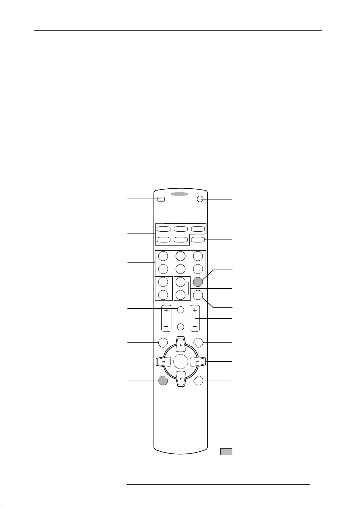
1.2 Remote Control Unit
Power OFF button
Select Active Input
Image profile switch
Color Adjust buttons
Display Information
Contrast Adjust buttons
Display Menu
OFF ........ OPERATE ......... ON
HDMI 1 HDMI 2
VIDEO ASPECT
CINEMA NATURAL DYNAMIC
C
USER
1
COLOR
+
COLOR
CONTRAST
S-VIDEO
N
USER
2
SHARP
+
SHARP
INFO
COMP
GAMMA
COLOR
BRIGHT
USER
TEMP
D
3
Power ON button
Screen Aspect Ratio
Gamma setting button
Sharpness Adjust buttons
Color Temperature button
Brightness Adjust buttons
HIDE
MENU
ENTER
EXIT
Hide Display
Exit to previous menu
Navigation buttons
Zoom and Focus settings
and Test Pattern button
LIGHTTEST
Backlight button
New settings are in bold letters
R699760 - DreamBee 2 User Manual 5
Page 6
1.0 INTRODUCTION
1.3 Quick Start
Plug your video source into the DreamBee 2
Connect your video source to the DreamBee 2 using one of the available inputs:
• HDMI 1 (version 1.3 with HDCP, supports digital SD, HD and PC formats)
• HDMI 2 (version 1.3 with HDCP, supports digital SD, HD and PC formats)
• VIDEO (supports analog SD signals)
• S-VIDEO (supports analog SD signals)
• COMPONENT (supports YPbPr, RGB and RGsB encoding, digital SD, HD up to 1080i and PC formats)
SD signals: NTSC, PAL, PAL-N, PAL-M, SECAM for analog and 480i/p, 576i/p for digital.
HD signals: 720p50/60 Hz, 1080i50/60 Hz, 1080p24/50/60 Hz.
PC formats: VGA, SVGA, XGA and SXGA @ 60 Hz, see page 11for more details.
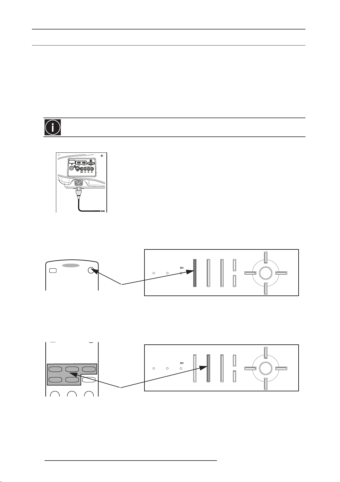
Plug the projector to the main power
•Before plugging in the Power Cord, ensure that all devices have been connected.
•Connect the power cord to the power input terminal of the projector.
Switch ON the projector
• With the Remote Control Unit (RCU) by pressing the [ON] button.
• Press the [Standby/ON] button at the Back Panel of the DreamBee 2.
OFF ........ OPERATE ......... ON
STANDBY/ON HIDEINPUT
WARNING LAMP
Power ON button
EXIT
ENTER
MENU
Switch ON the projector.
Select the source
• With the RCU by pressing the desired input button.
• Press sequentially the Input button at the back of the DreamBee 2 until you obtain the correct input.
Input sequence: HDMI 1 -> HDMI 2 -> VIDEO -> S-VIDEO -> COMP
HDMI 1 HDMI 2
S-VIDEO
VIDEO ASPECT
CINEMA NATURAL DYNAMIC
COMP
Select the video source with the RCU or using the Back Panel of the projector.
STANDBY/ON HIDEINPUT
WARNING LAMP
Select Active Input
EXIT
ENTER
MENU
Switch OFF
• With the RCU by pressing the [OFF] button.
• Press the [Standby/ON] button at the back of the DreamBee 2, and confirm the projector extinction by pressing
6 R699760 - DreamBee 2 User Manual
Page 7
2.0 FEATURE HIGHLIGHTS
the button again.
To prevent the lamp lifetime to get shortened, the projector cannot be switched OFF right after the lamp
warm-up. This is normal, wait 60 seconds until you can switch OFF the projector.
Never unplug the projector when it is switched ON, it may damage the lamp.
2.0 FEATURE HIGHLIGHTS
2.1 Motorized Focus and Zoom
The new Optical Lens features a motorized Zoom and Focus that can be accessed from the RCU or through the On
Screen Display using the Back Panel buttons of the projector.
The Focus and Zoom adjustments cannot be set manually.
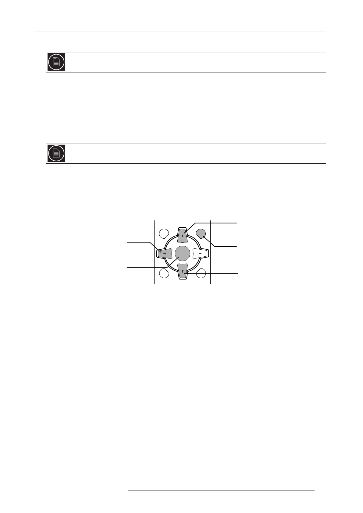
Using the internal green X-hatch pattern
• With the RCU:
a) Press repeatedly the [TEST] button on the RCU until you get the green X-hatch test pattern.
b) Then press [LEFT] button for 1 second until the Setting Focus window appears.
c) Use the [UP] and [DOWN] buttons to change the Focus.
d) Press [ENTER] to set the Zoom using [UP] and [DOWN] buttons.
Focus +
Green X-hatch pattern,
press [LEFT] button for 1
second to enter Zoom and
Focus menu.
Press [ENTER] to switch
between Focus and Zoom
adjustment
EXITMENU
ENTER
LIGHTTEST
Zoom +
Press [EXIT] to return to
Test Pattern Menu
Focus Zoom -
•From the Back Panel or RCU using the On Screen Display (OSD):
a) Press [MENU] button, and browse to the Install Menu.
b) Select the Test Pattern Menu.
c) Select the green X-hatch test pattern.
d) Press [LEFT] button for 1 second until the focus setting window appears.
e) Use [UP] and [DOWN] buttons to change the Focus.
f) Press [ENTER] to set the Zoom using [UP] and [DOWN] buttons.
Using an external test pattern (for advanced user)
a) Connect your calibrated source to an available input.
b) Set your programmable RCU or RS-232 device with ZoomT, ZoomW, Focus+ and Focus- functions. (See
page 15 for more details)
c) Display the desired test pattern and make the adjustments.
2.2 Gamma menu
Setting the correct value to the Gamma
Gamma is the relationship between the color values of the data and the color values displayed. The Gamma
coefficient makes it possible to adjust the brightness of the midtones only affecting the very bright and very dark
areas. If gamma is set to high, middle tones appear to dark. If it’s set too low, middle tones appear too light. The
Gamma correction can be set to Normal, Theatre1, Theatre2, Dynamic or Custom.
Normal uses the factory default calibration and will suit most setup.
Theatre1, Theatre2 and Dynamic use lower gamma values that can be directly changed using the RCU by pressing
[Gamma] button, choose the best setting to your ambient environment.
R699760 - DreamBee 2 User Manual 7
Page 8
2.0 FEATURE HIGHLIGHTS
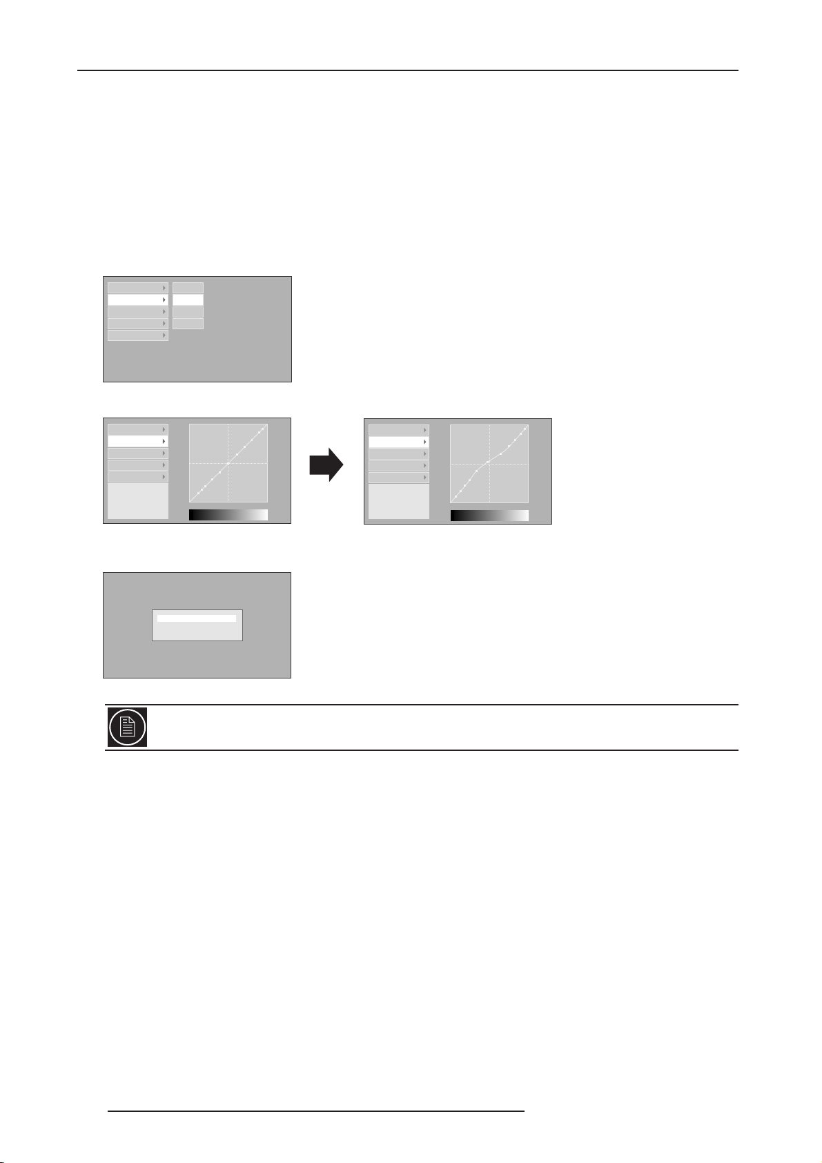
Custom (Gamma Setup)
Custom Gamma Setup allows a fine adjustment of the projector gamma setup. The Custom sub-menu gives access
to:
• Correction Value from1.8 up to 2.6
• Gamma Adjust Sub-Menu: advanced gamma curve setting.
•Save: save the adjusted gamma curve parameters into memory.
• Load: load a curve from memory.
• All Reset: reset the gamma curve parameters to default settings and apply the Correction Value [1.8 to 2.6].
Gamma Adjust Sub-Menu
Correction Value W
Gamma Adjust R
Save G
Load B
All Reset
Select the color channel to adjust:
W stands for White and will adjust Red, Green and Blue
R stands for Red only
G stands for Green only
B stands for Blue only
Correction Value
Gamma Adjust
Save
Load
All Reset
Adjustment Point (R)
X: 5 %
Y: 51
1023
512
050100(%)
Correction Value
Gamma Adjust
Save
Load
All Reset
Adjustment Point (R)
X: 5 %
Y: 51
1023
Select the point to adjust
[LEFT] and [RIGHT] buttons
512
Adjust the point coordinates
[UP] and [DOWN] buttons
050100(%)
Select Gamma Adjust to change the gamma curve
Do you save gamma data?
Yes : Push [ENTER] button
No : Push [EXIT] button
Press [EXIT] button to return to the main Menu.
Press [ENTER] to save the Gamma settings.
You can also use the PC-compatible software “ILAFPJ-Gamma” to set the Custom Gamma adjustment
using the RS-232 input. Check www.dreamvision.net for download.
8 R699760 - DreamBee 2 User Manual
Page 9

2.0 FEATURE HIGHLIGHTS
2.3 Setup Menu
Image Profile
The Image Profiles stores the following parameters:
• Contrast
•Brightness
• Color
• Sharpness
• DNR
• Color Temperature
• Gamma setting
• Offset
Use the predefined Profiles: Cinema, Natural or Dynamic. You can also configure your own Image Profile settings
are save it to one of the 3 available User Profiles.
Profile Memory
Manage your Image Profiles. You can save the Profile settings, Clear the User1, User2 and User3 Profiles and
Reset the predefined profiles Cinema, Natural and Dynamic to their default factory values.
Overscan (available with SD signal)
The SD signals are generally encoded into a frame which is larger than the active picture. The projector can
manually disengage the overscan feature and obtain the full original picture as it is encoded and sent to the
projector before the overscan crop.
The Overscan can be set to:
• ON (2.5%)
• OFF
Mask (available with HD signal)
The Mask features 3 overscan levels for HD signals: 2.5%, 5% and OFF.
2.4 Source Menu
Comp
You can configure the COMPONENT input of the DreamBee 2:
• YPbCb/PrCr: set the COMPONENT input to decode YPbCb/PrCr video signals.
• RGB: set the COMPONENT input to decode RGB video signals.
• RGsB: set the COMPONENT input to decode a SCART input (for European market). The RGsB connections
use the Component and Video inputs.
SCART
RGsB require Component and Video inputs.
R699760 - DreamBee 2 User Manual 9
Page 10
2.0 FEATURE HIGHLIGHTS
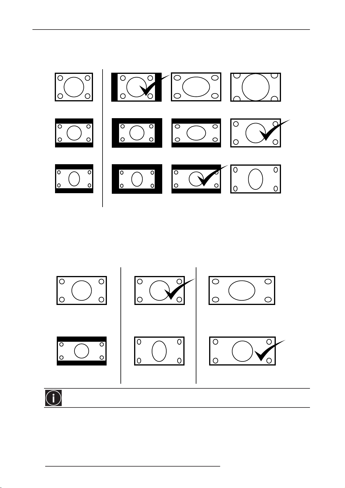
Aspect (available with SD signals)
Aspect Ratio: changes the aspect ratio of the picture to the screen. Select the Aspect Ratio to your convenience,
depending on the format of the signal.
VIDEO SOURCE ASPECT RATIO
SDTV 4:3
(full frame)
SDTV 4:3
(with black bands)
SDTV 4:3
compatible 16:9
(stretched picture)
4:3 16:9 Zoom
4:3 16:9 Zoom
4:3 16:9 Zoom
Screen Aspect Ratio
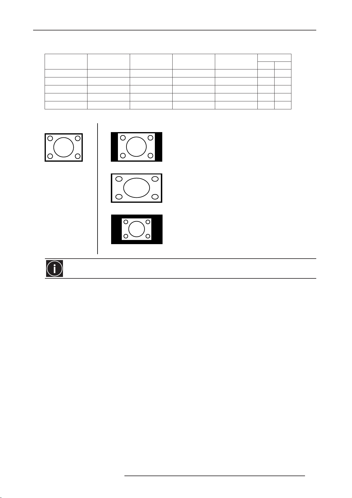
Ver tical Stretching (available with HD signals)
The V-stretch mode is available for any HD signals connected to HDMI1 or HDMI2 and COMP inputs and can be
used to vertically stretch the picture when using an anamorphic Lens.
VIDEO SOURCE V-STRETCH With Anamorphic Lens
HDTV , format 16:9
HDTV , format 2.35:1
The V-stretch value is stored into memory per resolution and refresh rate.
V-STRETCH is OFF
V-STRETCH is ON
The black bars are eliminated
The picture is horizontally stretched
The picture is optically restored
to its original aspect ratio.
10 R699760 - DreamBee 2 User Manual
Page 11
2.0 FEATURE HIGHLIGHTS
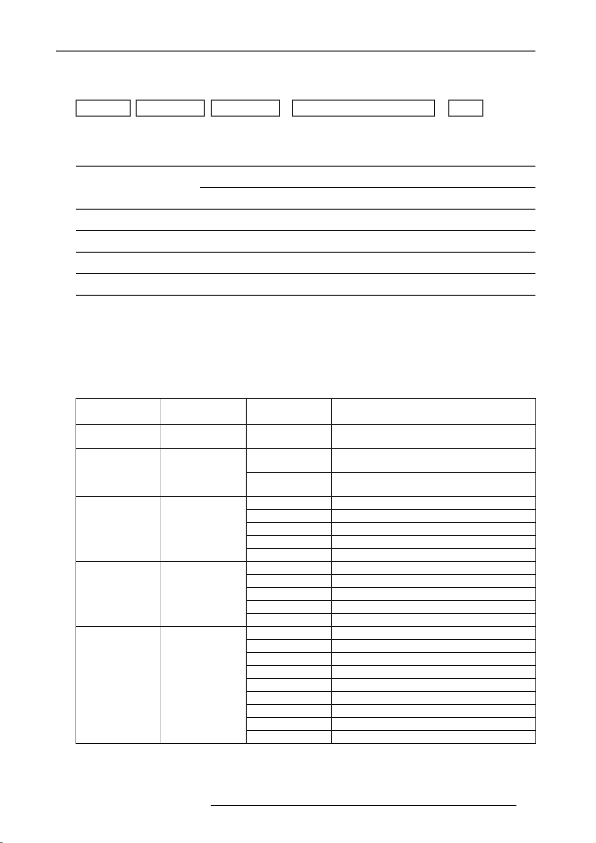
Resize (available with PC-compatible signals)
The PC-compatible supported formats are:
PC format Resolution fH fV pixel clock
VGA@60Hz (1) 640x480 31.500 kHz 60.000 Hz 25.200 MHz - VGA@60Hz (2) 640x480 31.469 kHz 59.940 Hz 25.175 MHz - SVGA@60Hz 800x600 37.879 kHz 60.317 Hz 40.000 MHz + +
XGA@60Hz 1024x768 48.363 kHz 60.004 Hz 65.000 Mhz - SXGA@60Hz 1280x1024 63.981 kHz 60.020 Hz 108.000 Mhz + +
PC SOURCE RESIZE
ASPECT enlarges the PC format until it fits the screen
height, the aspect ratio is not modified.
Polarity
H V
PC format: 1024x768
The Resize setting is not available for HDMI inputs.
ASPECT
PANEL enlarges the PC format until it fills the screen,
the aspect ratio is changed to 16:9.
PANEL
1:1 displays the PC format using a pixel to pixel mapping.
1:1
R699760 - DreamBee 2 User Manual 11
Page 12
3.0 INSTALLATION GUIDELINES
3.0 INSTALLATION GUIDELINES
3.1 Projection Distance
Projection Screen Size
Diagonal size
(Aspect Ratio 16:9)
60" (1524 mm) 52,3" (1328 mm) 29,4" (747 mm) 1821 mm - 3659 mm
83" (2108 mm) 72,3" (1837 mm) 40,7" (1034 mm) 2519 mm - 5062 mm
92" (2337 mm) 80,2" (2037 mm) 45,1" (1146 mm) 2792 mm - 5611 mm
110" (2794 mm) 95,9" (2435 mm) 53,9" (1370 mm) 3339 mm - 6709 mm
138" (3505 mm) 120,3" (3055 mm) 67,7" (1718 mm) 4188 mm - 8417 mm
150" (3810 mm) 130,7" (3321 mm) 73,5" (1868 mm) 4553 mm - 9149 mm
180" (4572 mm) 156,9" (3985 mm) 88,2" (2241 mm) 5463 mm - 10978 mm
200" (5080 mm) 174,3" (4428 mm) 98,1" (2491 mm) 6070 mm -12198 mm
• The projection screen sizes and projecting distances in the table above are provided only as a guide. Please use
them as reference during installation.
Projection Screen Size
Base size
(Aspect Ratio 16:9)
Projection Screen
Height
(Aspect Ratio 16:9)
DreamBee 2
Projecting Distance
minimum - maximum
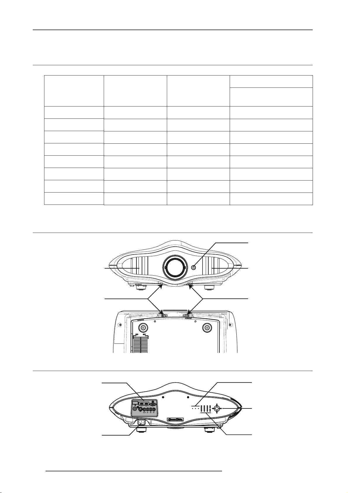
3.2 Vertical and Horizontal Offset setting
Front infra-red sensor
Air outlet Air inlet
Horizontal shift Dial
(-34% to +34%)
3.3 Rear side
Input Panel
Main Power
Vertical shift Dial
(-80% to +80%)
Operating LEDs
Navigation buttons
Operating buttons
12 R699760 - DreamBee 2 User Manual
Page 13

3.4 Operating LED
LED Status Description
WARNING RED An error occurs and prevents the projector to be switched ON.
ORANGE Lamp time exceeds 1900 hours, replace the lamp before 2000 hours.
LAMP
ORANGE Blinking An error occurs during projection or the lamp cover is not firmly closed
3.0 INSTALLATION GUIDELINES
WARNING
(red LED)
LAMP
(orange LED)
STANDBY/ON
(red / greenLED)
RED The projector is in STANDBY Mode.
RED Blinking The projector is in Cooling down Mode, wait until the fans stop.
STANDBY/ON
GREEN The projector is working.
GREEN Blinking
The picture is temporarily hidden, press [HIDE] button again to get the
picture.
3.5 Operating and Navigation Buttons
Button Description
Enter To select or confirm.
Enter
Up - down - left - right
Switch On/Off
Input
Hide
Exit
Menu
Up - down - left - right To navigate into Menu.
Switch On/Off To turn On or Off the projector.
Input To switch the input selection.
Hide To hide temporary the picture.
Exit To return to previous menu or cancel action.
Menu To display On Screen Display (OSD) Menu.
R699760 - DreamBee 2 User Manual 13
Page 14

3.0 INSTALLATION GUIDELINES
3.6 RS-232C PROTOCOL
Pin Assignment
15
69
Pin No. Signal Name Pin No. Signal Name
1 N/C 6 N/C
2 RD 7 N/C
3 TD 8 N/C
4 N/C 9 N/C
5 GND
External Control
Control of this unit is possible via a computer by connecting this unit to an automation device or computer with a
RS-232C cross cable (D-sub 9 pins). The commands to control this unit and the response data format against the
received commands are explained here.
Automation Device
Control Device
Computer with RS-232
RS-232 output
Communication Specifications
Communication specifications for this unit are as follows:
Baud Rate 19200 bps
Data Format Binary
Character Length 8 bits
Parity None
Start Bit 1 bit
Stop Bit 1 bit
Flow Control None
14 R699760 - DreamBee 2 User Manual
Page 15
Command Format
When sending a command to this unit, use the following data format:
3.0 INSTALLATION GUIDELINES
Header Proj. ID Command Com. Parameters LF
1 byte 2 bytes 2 bytes Var iable length: 0, 1 or 4 bytes 1 byte
Header : Designates the Command type. 2 possible headers:
! (21h): Assigns command to the projector (Command)
? (3Fh): Query data from the projector (Asking command)
Proj. ID : Designates the Projector Identification. Fixed to 89h 01h.
Command : Designates command.
Com. Parameters : Designates the command parameters. Variable length from 0 to 4 bytes.
LF : Designates the end of the data. Fixed to Line Feed (0Ah)
*[ ] is not necessary
[ ]
Response data format
Upon receiving a valid control command, the unit sends back a response data to the computer to confirm the
command: see DreamBee User Manual (ref. R699740) for more details.
Available Commands and Parameters
a) Commands
Command
Header (21h)
Connection Check 00h 00h none Checks whether communication between the
Power ON/OFF 50h 57h 31h If the projector is in Standby mode, this command
Switch Input 49h 50h 30h Switch active input to S-Video
Switch gamma table 47h 54h 30h Switch Gamma to NORMAL
Gamma coef. 47h 50h 30h Set gamma coefficient to 1.8
ASCII code Parameters Description
projector and the computer is working
switch this unit ON.
30h If the projector is powered ON, this command
switch this unit into Standby Mode.
31h Switch active input to Video
32h Switch active input to Comp.
36h Switch active input to HDMI 1
37h Switch active input to HDMI 2
31h Switch Gamma to THEATER1
32h Switch Gamma to THEATER2
33h Switch Gamma to DYNAMIC
34h Switch Gamma to CUSTOM
31h 1.9
32h 2.0
33h 2.1
34h 2.2
35h 2.3
36h 2.4
37h 2.5
38h 2.6
R699760 - DreamBee 2 User Manual 15
Page 16

3.0 INSTALLATION GUIDELINES
Test Pattern 54h 53h 30h Do not display
36h Display Grey Staircase
37h Display Red Staircase
38h Display Green Staircase
39h Display Blue Staircase
Emulate RCU 52h 43h xxh xxh xxh xxh The command sent is executed as a Remote
Control Unit command. (See below the RCU
Command list and Parameters)
Focus + 52h 43h 37h 33h 33h 31h Focus + adjustment:
Use 20ms loop time for fast adjustment, 100ms for
fine adjustment.
Focus - 52h 43h 37h 33h 33h 32h Same as Focus +
Zoom T 52h 43h 37h 33h 33h 35h Zoom T adjustment:
Use 20ms loop time for fast adjustmenet, 100ms
for fine adjustment.
Zoom W 52h 43h 37h 33h 33h 37h Same as Zoom T
b) Emulate Remote Control Unit Commands (4 bytes)
To emulate a command sent by the RCU, you should send the following command:
Header: 21h Proj. ID: 89h 01h Command: 52h 43h Parameters: 4 bytes
Choose the correct Parameters listed below according to the command
Remote Control Button name Parameters / ASCII IR codes
Up button 37h 33h 30h 31h
Down button 37h 33h 30h 32h
EXIT 37h 33h 30h 33h
Operate ON 37h 33h 30h 35h
Operate Off 37h 33h 30h 36h
HIDE 37h 33h 31h 44h
MENU 37h 33h 32h 45h
ENTER 37h 33h 32h 46h
Focus + 37h 33h 33h 31h
Focus - 37h 33h 33h 31h
Right button 37h 33h 33h 34h
Zoom T 37h 33h 33h 35h
Left button 37h 33h 33h 36h
Zoom W 37h 33h 33h 37h
VIDEO 37h 33h 34h 42h
S-VIDEO 37h 33h 34h 43h
COMP. 37h 33h 34h 44h
TEST 37h 33h 35h 39h
Cinema 37h 33h 36h 39h
Natural 37h 33h 36h 41h
Dynamic 37h 33h 36h 42h
User 1 37h 33h 36h 43h
User 2 37h 33h 36h 44h
User 3 37h 33h 36h 45h
HDMI 1 37h 33h 37h 30h
HDMI 2 37h 33h 37h 31h
INFO 37h 33h 37h 34h
GAMMA 37h 33h 37h 35h
Color Temp. 37h 33h 37h 36h
Aspect 37h 33h 37h 37h
Contrast (+) 37h 33h 37h 38h
Contrast (-) 37h 33h 37h 39h
Brightness (+) 37h 33h 37h 41h
16 R699760 - DreamBee 2 User Manual
Page 17
3.0 INSTALLATION GUIDELINES
Brightness (-) 37h 33h 37h 42h
Color (+) 37h 33h 37h 43h
Color (-) 37h 33h 37h 44h
Sharp (+) 37h 33h 37h 45h
Sharp (-) 37h 33h 37h 46h
Example:
To emulate Brightness (+), send the command: 21h 89h 01h 52h 43h 37h 33h 37h 41h 0Ah
c) Examples
You want to... Command (PC -> Projector) Response Data (Projector -> PC)
Check the connection between
the projector and the computer
Switch the projector ON 21h 89h 01h 50h 57h 31h 0Ah ACK: 06h 89h 01h 50h 57h 0Ah
Switch the projector OFF 21h 89h 01h 50h 57h 30h 0Ah ACK: 06h 89h 01h 50h 57h 0Ah
Switch the projector OFF with
OSD confirmation
(Emulate RCU)
Change Active Input to Comp. 21h 89h 01h 49h 50h 32h 0Ah ACK: 06h 89h 01h 49h 50h 0Ah
Display On Screen Menu
(Emulate RCU)
Change the Gamma coefficient
value to 2.2
Enlarge the picture using the
motorized Zoom
Ask the projector its power state
The projector being powered ON
Ask the projector its Active Input
S-Video being active
21h 89h 01h 00h 00h 0Ah ACK: 06h 89h 01h 00h 00h 0Ah
21h 89h 01h 52h 43h 37h 33h 30h 36h 0Ah ACK: 06h 89h 01h 52h 43h 0Ah
21h 89h 01h 52h 43h 37h 33h 32h 45h 0Ah ACK: 06h 89h 01h 52h 43h 0Ah
21h 89h 01h 47h 50h 34h 0Ah ACK: 06h 89h 01h 47h 50h 0Ah
repeat the command below:
21h 89h 01h 52h 43h 37h 33h 33h 37h 0Ah
20ms loop time for fast adjustment and
100ms for fine adjustment.
3Fh 89h 01h 50h 57h 0Ah
3Fh 89h 01h 49h 50h 0Ah
ACK: 06h 89h 01h 52h 43h 0Ah
ACK: 06h 89h 01h 50h 57h 0Ah
Rsp : 40h 89h 01h 50h 57h 31h 0Ah
ACK: 06h 89h 01h 49h 50h 0Ah
Rsp : 40h 89h 01h 49h 50h 30h 0Ah
R699760 - DreamBee 2 User Manual 17
Page 18

4.0 MENU STRUCTURE
4.0 MENU STRUCTURE
MAIN MENU SUBMENU AVAILABLE OPTIONS
Image Image Adjust Contrast -50 +50
Brightness -30 +30
Color -50 +50
Tint (for NTSC sources) -30 +30
Sharpness -30 +30
DNR (Digital Noise Reduction 0 +30
Color Temp. Presets: Low, Middle, High
Memory 1:
Red -255 to 0
Green -255 to 0
Blue -255 to 0
Memory 2:
Red -255 to 0
Green -255 to 0
Blue -255 to 0
Gamma Normal
Theater1
Theater 2
Dynamic
Custom:
Correction Value 1.8 to 2.6
Gamma Adjust see page 8
Save
Load
All Reset
Offset Red -60 +60
Green -60 +60
Blue -60 +60
Pixel Adjust Horiz. Red 1 to 7
Horiz. Green 1 to 7
Horiz. Blue 1 to 7
Ver t . Red 1 to 5
Vert. Green 1 to 5
Vert. Blue 1 to 5
18 R699760 - DreamBee 2 User Manual
Page 19

4.0 MENU STRUCTURE
Setup Image Profile
Parameters:
Contrast / Brightness
Color / Sharpness
DNR / ColorTemp
Gamma / Offset
Profile Memory Save User1
Picture Position Adjust the horizontal and vertical position of
HDMI Input Level
(Available for HDMI1 and 2 inputs)
Mask
(for High Definition picture)
Overscan
(for Standard Definition picture)
Source COMP
(for Component Input)
HDMI
(for HDMI 1 and HDMI 2 Inputs)
Aspect
(for Standard Definition picture)
V-Stretch
(for High Definition picture)
Resize
(for PC format picture)
Film Mode Auto
Color System
(for Video or S-Video Inputs)
Black Level
(for NTSC sources)
Cinema (Movie quality in dark room)
Natural (Picture as is in dark room)
Dynamic (Bright scenes or bright room)
User1 (User defined)
User2 (User defined)
User3 (User defined)
Save User2
Save User3
Clear User1
Clear User2
Clear User3
Reset Cinema
Reset Natural
Reset Dynamic
the picture on the screen
Standard
Enhanced
OFF, 2.5%, 5%
OFF
ON (2.5%)
Y PbCb/PrCr
RGB
SCART
Auto (Autodetect the HDMI color space)
YCbCr (4:4:4)
YCbCr (4:2:2)
RGB
4:3
16:9
Zoom
OFF
ON
Aspect
Panel
1:1
Off
Auto, NTSC, NTSC4.43, PAL, PAL-M, PALN, SECAM
0%, 7.5%
R699760 - DreamBee 2 User Manual 19
Page 20

4.0 MENU STRUCTURE
Install Menu Position Upper Left
Upper Center
Upper Right
Left Center
Center
Right Center
Lower Left
Lower Center
Lower Right
Menu Display 15 sec. The menu fade out after 15 sec.
On Must press [EXIT] to exit menu
Line Display
(Display the active input when
switching input)
Flip H.
(for rear projection)
Flip V.
(for ceiling mounting)
High Altitude On
Func. Back Color
(background color when no signal)
Sleep Timer
(The projector goes automatically
into Standby Mode when no signal)
D-ILA Logo
(Logo displayed during startup)
Lamp Power Normal (170W)
Test Pattern* Test Patterns for Focus and Zoom
Language Japanese, English, German, Spanish,
Info. Input Display selected video Input
Format Display the type of current input video
H Frequency (PC format picture) Display horizontal frequency
V Frequency (PC format picture) Display the vertical frequency
Lamp Time Display the accumulated hours usage of the
5 sec.
Off
On
Off
On
Off
Off
Blue
Black
15 (in minutes)
30
60
Off
On (D-ILA logo is displayed 5 sec.)
Off
High (200W)
adjustment
Italian, French, Portuguese, Dutch, Swedish,
Norwegian, Chinese (Simplified)
lamp
*TEST PATTERN MENU
When the green X-hatch pattern is displayed, press the [LEFT] button for 1 second to popup the Focus and Zoom
menu. Press the [ENTER] button to change Focus adjustment to Zoom adjustment. Press the [EXIT] button to
return to Test Pattern selection.
20 R699760 - DreamBee 2 User Manual
Page 21

5.0 MISCELLANEOUS
5.1 Specifications
Overview
The DreamBee 2 uses the latest technology developed for professional projectors.
Emission Method LCoS (Reflective Active Matrix Principle)
Display Panel/Size 0.7" panel
Native Resolution 3x 1920 x 1080 pixels
Contrast Ratio 30,000:1
Projection Lens Throw Ratio 1.4:1 - 2.8:1 2x optical Zoom
Motorized Zoom and Focus
Brightness 900 ANSI Lumens
Light-source Lamp 170 W Ultra-high pressure mercury lamp
Screen Size 60" to 250" diagonal (Aspect ratio 16:9)
Distance range from 1,82 m to 12 m
Input Signals
Video Input NTSC, PAL, SECAM
S-Video Input NTSC, PAL, SECAM
Component Input (YPbPr, RGB and RGsB) 480i/p, 576i/p, 720p50/60, 1080i50/60
VGA(1), VGA(2), SVGA, XGA, SXGA
HDMI 1 Input 480i/p, 576i/p, 720p50/60, 1080i50/60, 1080p24/50/60
VGA(1), VGA(2), SVGA, XGA, SXGA
HDMI 2 Input 480i/p, 576i/p, 720p50/60, 1080i50/60, 1080p24/50/60
VGA(1), VGA(2), SVGA, XGA, SXGA
Color System NTSC, NTSC4.43, PAL, PAL-N, PAL-M, SECAM
Input Sync Frequency
Analog Inputs 74.5 Mhz
Digital Inputs 225,0 Mhz
Power Requirements AC 100 V - 240 V AC, 50 Hz/60 Hz
Power Consumption 280W (2.7W in standby mode)
Operation Environment Temperature: +5°C to +35°C
Storage Temperature: -10°C to +60°C
Humidity: 20 % to 80 % (No condensation)
Dimensions
(Width x Height x Depth)
Net Weight 11,0 Kg - 24.5 lbs
585 x 205 x 470 mm - 23.0" x 18.5" x 8.0"
(Excluding lens and protrusion portion)
5.0 MISCELLANEOUS
• Design and specifications are subject to change without prior notice.
• Please note that some of the pictures and illustrations may have been abridged, enlarged or contextualized in
order to aid comprehension. Images may differ from the actual product.
R699760 - DreamBee 2 User Manual 21
Page 22

5.0 MISCELLANEOUS
5.2 Dimensions
205 mm 8.0’’
18.5’’
470 mm
585 mm
23.0’’
585 mm
23.0’’
470 mm
18.5’’
22 R699760 - DreamBee 2 User Manual
Page 23

Contact Information:
TEC - DreamVision
7, rue La CAILLE, 75017 Paris - FRANCE
e-mail : sales@dreamvision.net, Web: www.dreamvision.net
Page 24

 Loading...