

PICCADILLY TV BED
PLEASE READ this sheet prior to assembly to
familiarise yourself with the various stages of
construction. Carefully open the pack supplied and
check the contents against the parts and fittings check
list in this guide.
Do not destroy any of the packaging until you are
certain that you have all the necessary parts for the
assembly.
Please ensure that the packaging is disposed of in
a safe environmentally friendly way.
CAUTION: There are small components used in the
construction of this unit. These loose items should be
kept away from young children whilst assembling your
unit, to avoid the danger of a choking hazard.
IMPORTANT: BEFORE RAISING THE TV LIFT, REMOVE ANY TRANSIT PACKING OR WRAPPING FROM INSIDE THE FOOTBOARD.
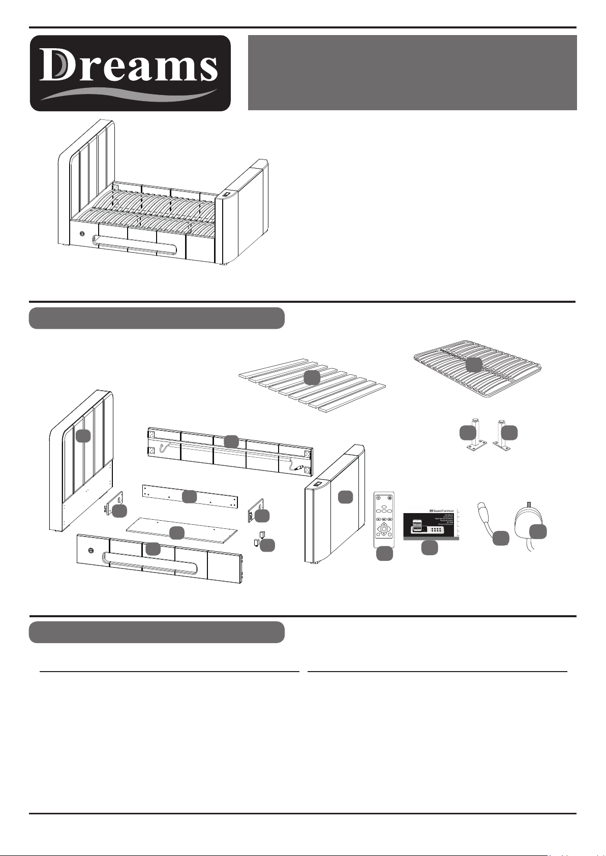
Parts Identification
13
12
13
1
7
6
5
4
3
8
9
Parts Checklist
Ref. Description DescriptionRef.
1
2
3
4
5
6
7
8
9
Headboard
Footboard
Right Side Panel
Left Side Panel
Media Tray Base Panel
Media Tray Left Side Panel
Media Tray Back Panel
Media Tray Right Side Panel
Media Tray Support Legs
Qty
1
1
1
1
1
1
1
1
2
10
11
12
13
14
15
*Only supplied if upgraded sprung slat frame system chosen
Legs P&Q only supplied with sprung system
P Q
14
2
BT USB
REPEAT
14
iPod
AUX
ENTER
VOL +VOL -
MENU
15
Note:
Standard wooden slat frame (part 12)
Upgraded sprung slat frame (part 13)
13 Amp Power Lead
Aerial Lead
Wooden Slats
Metal Sprung Slat System*
Remote Control - Sound Dock
Operation Guide - Sound Dock
11
10
Qty
1
1
1 Set
1 Frame
1
1
Page 1 of 9 V2
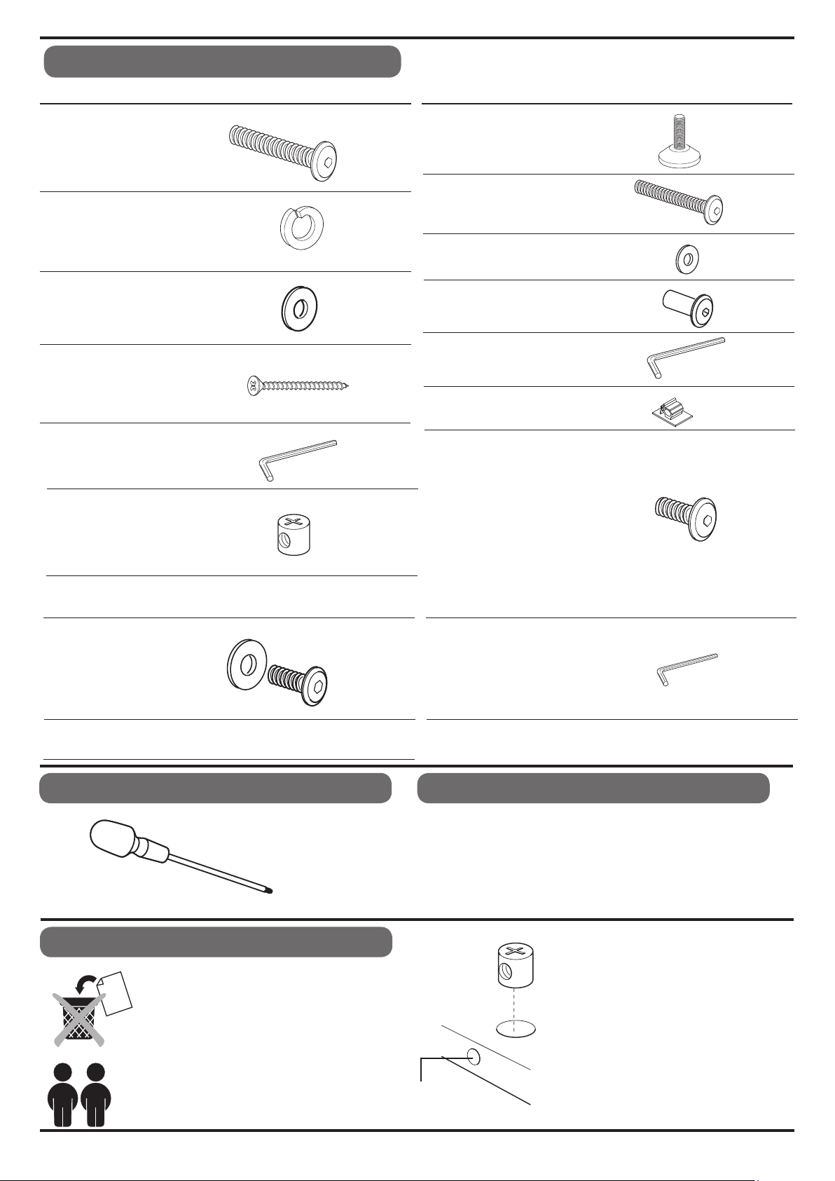
Fittings Checklist
Bolt (M8x30mm)
A
Spring Washer
B
Washer (17x8mm)
C
Screw (5x50mm)
D
E
Allen Key (8mm)
F
Barrel Nut
Qty Code Description
x22
x20
x20
x13
x1
x13
G
H
I
J
K
L
Adjustable Foot
Bolt (M6x40mm)
Washer (16x6mm)
Sleeve Nut (M6x6mm)
Allen Key (6mm)
Cable Clip
These parts are supplied with the optional
sprung slat frame.
O
P
Bolt (M6 x15mm)
Centre Support Leg
QtyCode Description
x2
x6
x6
x6
x1
x2
x8
x1
M
Screw-Washer set
Additional Tools Required
Crosshead Screwdriver
General Hints & Tips
Please retain your Assembly Instruction and
tools provided, for future use. Periodically
check that all bolts are still tight.
This assembly requires two
people.
Q
Support Leg
TV INSTALLATION KIT
x4
N
Allen Key
Care & Maintenance
In the unlikely event of missing or damaged parts, please
contact the customer service team on 08442 920000. When
calling this number , please quote the part code reference
numbers shown in this leaflet, to properly
replacement parts.
To keep your bed in pristine condition, wipe over with a clean,
slightly dampened cloth.
Intersecting
Hole
x2
x1
identify spare or
When they are supplied and are part
of the assembly of this bed, ensure
that barrel nuts are fitted the correct
way so the hole is facing towards the
intersecting hole.
We recommend the bed is
assembled
be located in.
the room it will
in
Page 2 of 9
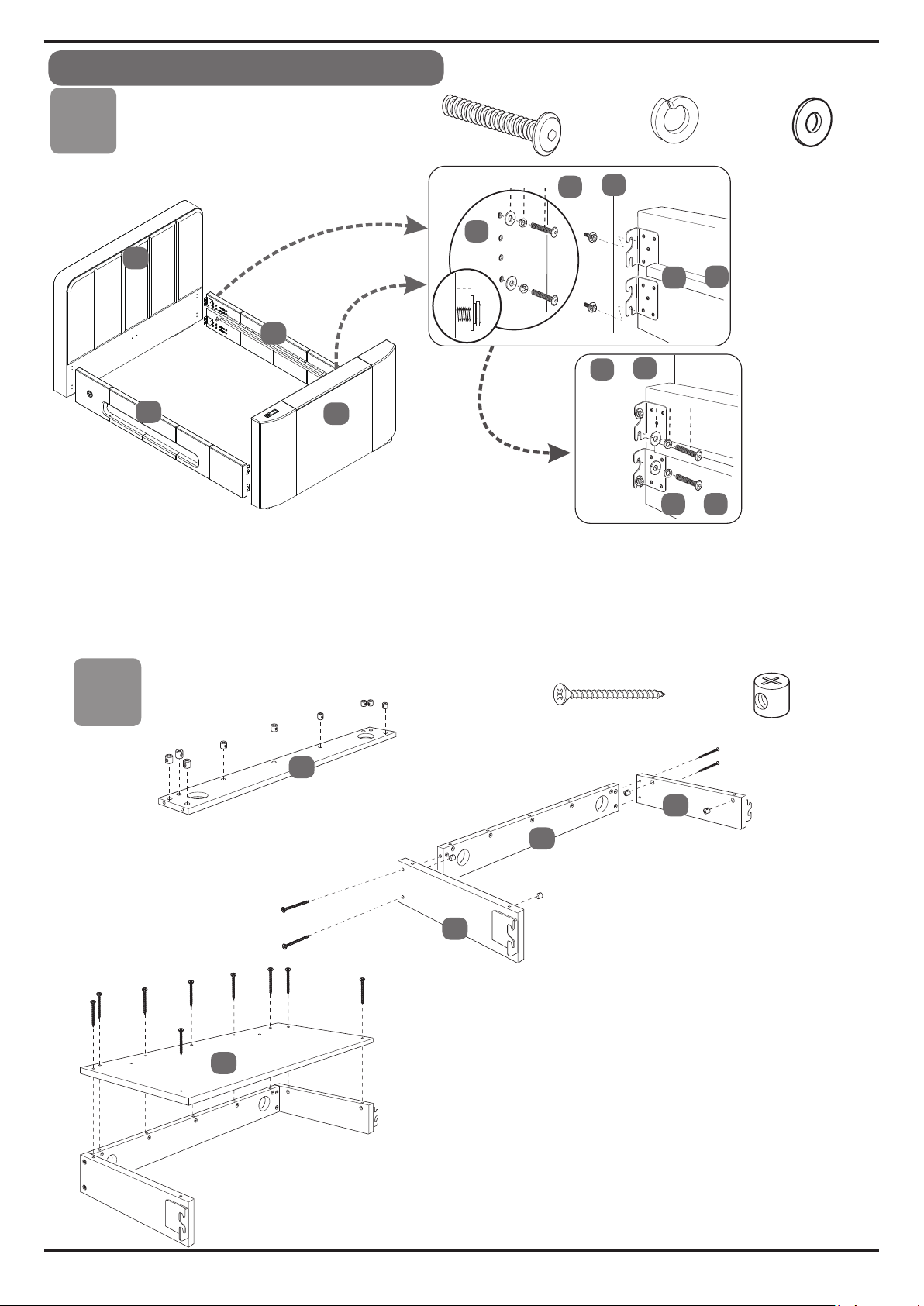
Bed Assembly
Stage
Stage
1
1
1
x16
4
3
&
A
B
4
3
&
&
B
2
2
1
&
C
A
C
B
2
10mm
3
4
2
x16
A
1
C
x16
Fit the bolts (A),
Note: Do no t fully locate th e bo lts, but leave 10mm protruding.
Fit the side panels (3 & 4) to th e footboard locating the brackets behind the flat washers.
Fit the bolts (A), sprin g washers (B) , and flat w as hers (C) through the brackets in the central set of holes.
.
Once all four corners a re located, make sure the bed is square, then tighten the bolts using allen key (E).
Stage
spring washers (B) , and flat washers (C) to the holes in the footboard (2) as shown.
2
7
8
D
7
x13
6
F
x13
Fit the barrel nuts (F), to the Media Tray back panel (7),
making sure the screw hole aligns with the intersecting
hole (see hints & tips section).
5
Fit the tray side panels (6
using the screws
Fit barrel nuts (F) to the inside sides of the tray side
panels as shown.
Fit the tray base panel
secure through into the barrel nuts previously fitted.
(D) into the barrel nuts.
),
to the back panel (7
& 8
(5) using the screws (D) to
)
Page 3 of 9

Bed
Stage
Assembly
3
Bed Assembly continued
Stage
4
A
9
Fit the adjustable feet (G) to the underside
of the tray support legs (9) screw into
Fit the support legs (9) to the underside of
the tray base panel using the bolts (A) to
secure. Fully tighten using the Allen Key (E).
9
9
A
x4
B
x2
x4
G
C
x2
place.
x4
4
Push bolt (A) through spring washer (B) and flat washer (C),
Hold tray firmly against
When all screwed in place,
Adjust the feet (G) so bottom of tray is level.
side panel (4) as shown and screw-in
tighten bolts 100%.
x4 bolts.
Page 4 of 9

Bed Assembly
Stage
5
Wall Socket
Aerial
1
Connect the power cable (10) and
aerial cable (11) into the sockets
3
2
4
HDMI 1
TV
HDMI 2
MODEL:Piccadilly
POWER SUPPLY: AC 220-240V~50Hz
T
POWER CONSUMPTION:
S/N:
RISK OF ELECTRIC SHOCK
TO REDUCE THE RISK OF ELECTRIC SHOCK.
DO NOT REMOVE COVER (OR BACK)
NO-USER SERVIC EABLE PARTS INSIDE REFER
SERVICING TO QUALFIED SERVICE PERSONNEL
20131228
CAUTION
DO NOT OPEN
CAUTION
TV : MAX 55W
TV LEFT : 50W
Radio: 15W
!
located at the bottom of the footboard (2)
and then connect to your wall sockets.
Note that the plug has an earth blade and the
wall socket must have an earth terninal too.
The plug connection must be easy to reach
if you need to disconnect the power.
WARNING
!
HAZARDOUS VOLTAGE
Contact mav cause
electric shock or burn.
MADE IN CHINA
This unit is to be ser
trained personnel only.
AC 220V ~ 240V
vied by
11
Music dock remote control
eye. Point remote here to
operate dock - see guide
in accessory box.
FOOTBOARD
2
Aerial Socket
On each side panel of the bed is a switch to
operate the TV Lift.
The switches are connected to the TV Lift by
a DIN
sure you plug them in properly - align the arrows
on the labels and push right in.
Power Socket
HDMI 1 & 2
10
plug on each side of the footboard - make
2
3
&
4
Page 5 of 9
Switch DIN plug

BED ASSEMBLY
Stage
6
TELEVISION INSTALLATION
Ipod Music Dock - instructions
in the accessory box.
TV INSTALLATION KIT
M
x4
TV Mounting Bracket
Maximum loading - 20 Kg.
N
x1
PlatformPlatform
Stage
7
BED SLA
T FIXING
12
12
12
M
N
H
Lay the set of slats (12) onto the metal
slat support rails, on each side of the bed.
Align the first and last slat with the holes
at each end of the rails, and secure in place
using the bolts (H), washers (I) and
sleeve nuts (J). Fully tighten using
the allen key (K).
Once secure fix the centre slat using
the bolts as before. Use all x6 bolt sets.
x6
I
J
x6
x6
Page 6 of 9

Bed Assembly
Stage
7a
UPGRADE SPRUNG SLAT SYSTEM
Q
P
13
Q
H
O
Open the metal slat frame and lay face down on the working
surface.
Fit the support legs (P & Q) to the positions shown, securing
with the bolts (O). Fully tighten using the allen key (K).
Carefully turn the slat frame over, and position onto the metal slat
support rails. Align the frame with the fixing holes at each
end of the rail and secure using just 4 sets of the bolts (H),
washers (I) and sleeve nuts (J). Fully tighten using the allen key (K).
Finally, please ensure that all bolts are fully tightened
before the bed is used.
EITHER 12 OR 13 WILL BE SUPPLIED - BOXED SEPARATELY.
x4
x8
I
J
x4
x4
13
13
13
Page 7 of 9

Do not place power cables or other mains powered extension cables where they can be walked on.
During an electrical or lightening storm - disconnect the power completely as a precaution.
Always un-plug the power when going on holiday or when the bed is not used for an extended period.
Never touch moving parts or insert anything into the footboard of the bed - this could seriously damage your apparatus, cause injury
and shall void manufacturer's warranty .
At all times keep others, especially children, well clear of the foot end of the bed. Do not let them touch anything.
If you have young children in the home always disconnect the power at the wall socket for extra safety.
Never allow anyone to sit on the foot end of the bed.
To avoid electric shock - never touch anything inside the footboard of the bed. If you have a problem, ring Customer Services.
Make sure that the 3 pin plug, under the bed at the front of the foot end, is pushed right in. To remove it - pull the plug, NOT the wire.
If the apparatus does not operate normally, or if there is an unusual noise, dis-connect power and call Customer Services.
The 3 metre cable supplied with the bed, has a 13 amp UK plug which is earthed.
It is essential that the wall socket is properly earthed as well - otherwise there is a risk of damage or electric shock. If in doubt, ask an
electrical engineer to check your system.
To turn off the power, dis-connect the plug from the wall socket - this should be readily accessible at all times.
Do not interfere with any wires or connections as warranty will be voided and because it is dangerous to do so.. call on an expert for help.
TV BED SAFETY INFORMATION
It is very important not to not place any vessel containing liquids (drinks, vase of flowers etc.) on the top of the TV footboard which
may accidentally spill and could enter the footboard or audio system. This could cause damage to the TV, the TV lifting equipment or
the Audio dock. This dock has it’s own Operation Guide, packed inside the accessory box - there is a second guide for the audio
Remote Control. If for any reason the apparatus does get wet, disconnect power and call the supplier’s Customer Services Help Line -
08442 920000.
Do not expose the bed or apparatus to an undue level of heat - keep away from radiators.
Disconnect power plug from wall socket before cleaning the apparatus.
To keep bed clean, we recommend that the bed be wiped over with a slightly dampened cloth; disconnect power before cleaning.
In the accessory box are remote controls for Sound Dock and the TV - both of these use pencil batteries.
There are strict controls for disposal of batteries - your local council can advise on how to safely dispose of them.
Never burn batteries on an open fire as they could explode.
.
Before fixing the slats to the Bedstead, please follow the television installation instructions below:
1.
Connect the power cable ( 10 ) and aerial cable ( 11 ) to the sockets located at the bottom of the footboard ( 2 )
and then connect to your wall sockets. Connect media using the HDMI sockets (HDMI cables not supplied).
Raise the
2.
3.
Unpack your television and, if tted, remove any screws from the back of the TV.
Connect the television to the TV mounting bracket using the screw-washer set ( M ).
4.
If necessary you can adjust the bracket up and down to align with the screw xing points, by loosening the
thumb-screws on the back of the TV Lift and aligning the brackets with the xing holes.
Carefully tighten the screw ( M ) using the allen key ( N ) - the screws & allen key can be found in the TV
Installation kit, in the main hardware pack.
Connect the power and aerial cables to the television making sure the cables are not loose. If necessary use
5.
spare clips ( L ) to route cables safely.
6.
The television can now be operated following the TV manufacturers Operation Guide packed inside the accessory box.
7.
To lower the television back into the footboard, press one of the side panel DOWN buttons (BOTTOM half of the switch).
When DOWN button is pressed, TV will retract into footboard and turn off automatically at the bottom. .
When UP button is pressed - TV rises and turns itself back on automatically. .
Trouble shooting
If your television does not operate please check all the power connections, both to the wall and to the socket
1.
in the footboard. Make sure TV is switched on. Note: TV will only work when it is in the up position.
2.
If the TV Lift does not operate, try each switch in turn. - if neither switch operates - press the button twice.
Check that the power to the controller is on. It may
3.
If the television or TV Lift still fails to operate there may be a problem that can be checked by our
technicians. Call the Customer Services number for help and information - 08442 920000.
IMPORTANT :
please consult a qualied electrician. The mains electric powering this bed, must have an earthed supply.
TV lift by pressing one of the UP buttons located on either side rail of the bed (TOP half of the switch).
Care should be taken when connecting electrical items. If in any doubt over the connections
8 of 9

POINT AT GRILL ABOVE
RH SPEAKER
2
INPU T
AUDIO SYSTEM REMOTE CONTROL
1. Turns audio system On / Off
1
2. Cycle from iPod/iPhone mode to BT(Bluetooth) mode, or SD/USB mode or AUX mode
INPUT
11
12
iPod
4
6
7
8
AUX
BT
SD
3
5
9
10
13
3. Change to iPod/iPhone mode
iPod
4. Change to AUX mode
AUX
5. Change to BT mode
BT
6. Change to SD/USB mode
SD
7. Sk
ip to the previous track
(Bluetooth)
8. Skip to the next track
14
9. Play/Pause
10. Turns night-light On / Off
11. When this button is pressed, it will increase the bass level
12. When this button is pressed, it will decrease the bass level
13. When this button is pressed, it will increase the volume
14. When this button is pressed, it will decrease the volume
9 of 9
 Loading...