

MANHATTAN STORAGE BED
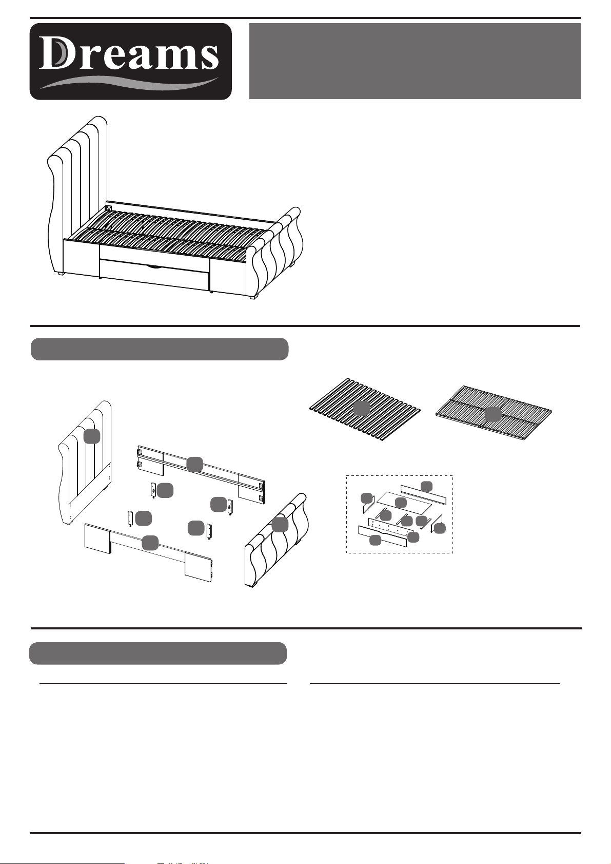
Parts Identification
PLEASE READ
yourself with the various stages of construction. Carefully
open the pack supplied and check the contents against the
parts and fittings check list.
Do not destroy any of the packaging until you are certain
that you have all the necessary parts for the assembly.
Please ensure that the packaging is disposed of in a
safe environmentally friendly way.
CAUTION: There are small components used in the
construction of this unit. These loose items should be kept
a way from young children whilst assembling your unit to
avoid the danger of choking hazards.
this sheet prior to assembly to familiarise
4
5
1
Parts Checklist
Ref.
1
2
3
4
5
6
7
Description
Headboard
Footboard
Side Rail
Wooden Slats
Metal Sprung Slat System*
Drawer Front Panel
Drawer Side Panel
11B
3
11A
11B
11A
3
Qty
1
1
2
1 set
1 frame
2
4
2
Ref. Description
8
9
10
11A
11B
12
13
7
12
6
Note:
Standard wooden slat frame (part 4)
Upgraded sprung slat frame (part 5)
Drawer Front Panel ii
Drawer Bottom Panel
Drawer Back Panel
Adjustable Support Leg
Adjustable Support Leg
Bottom Support Rails
Bottom Support Rails
10
9
12
13
8
Drawer x2
7
Qty
2
2
2
2
2
4
2
*Only supplied if upgraded sprung system chosen
Page 1 of 6
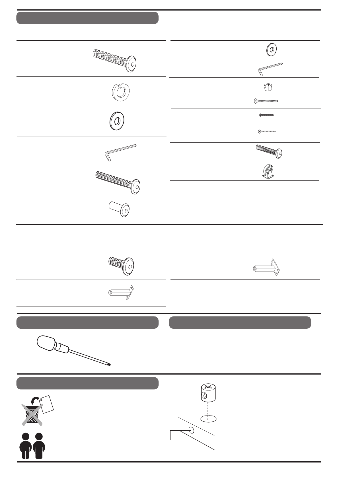
Fittings Checklist
Bolt (M8x30mm)
A
B
Spring Washer (8mm)
Flat Washer (8mm)
C
D
E
Allen Key (5mm)
Bolt (M6x40mm)
QtyCode Description
x16
x16
x24
x1
x6
Code Description
Flat Washer (6mm)
G
H
L
M
N
Allen Key (4mm)
I
Plastic Nut
Screw (5x50mm)
J
K
Screw (3x20mm)
Screw (4x30mm)
Bolt (M8x45mm)
Wheel
Qty
x6
x1
x28
x28
x40
x16
x8
x10
F
Sleeve Nut (M6x15mm)
x6
Note: The following fittings will be found in the box which contains the sprung slat Frame. They are not in the assembly
kit for the bed itself.
O
Bolt (M6x15mm)
Q
Slat Support Legs
Additional Tools Required
Crosshead Screwdriver
x8
x2
Slat Centre Support
P
Leg
x1
Care & Maintenance
In the unlikely event of missing or damaged parts, please
contact the customer service team on 08442 920000.
When
calling this number, please quote the part code
reference numbers shown in this leaflet when
requesting spare or replacement parts.
General Hints & Tips
Please retain your Assembly Instruction and
tools provided, for future use. Periodically
check that all bolts are still tight.
This assembly requires two
people.
Intersecting
Hole
Page 2 of 6
fitting barrel nuts into
When
the
fitted
hole is facing towards the
intersecting hole.
We recommend the bed is
assembled
be located in.
panels, ensure they are
the correct way so the
the room it will
in

Bed Assembly
Stage
1
A
x8
B
x8
C
x8
A
C
B
1
1
10mm
3
3
3
2
Fit the bolts (A), spring washers (B), and flat washers (C) to the holes in the headboard (1) and footboard
(2) as shown. Note: Do not fully locate the bolts, but leave 10mm protruding.
Fit the side rails (3) to the headboard and footboards locating the fixing brackets behind the flat washers.
Once all four corners are located check the bed is square, then fully tighten the bolts using the allen key (D).
Stage
2
11B
11A
3
3
11A
11B
M
M
x8 x8
C
C
ARROWS ON LABELS
POINT TO EACH OTHER
11A
Fit pairs of adjustable support legs to side rails (
Page 3 of 6
11A &11B) - fix them into pre-threade
d holes with bolt/washer (M&C).

Bed Assembly
Stage
3
BED SLAT FIXING
E
x6
G
x6
Stage
3a
4
4
UPGRADE SPRUNG SLAT SYSTEM
Q
F
Lay the set of slats (4) onto the slat
support rails on the side rails.
Align the first and last slat with the
end of the rails, and secure in place
using the bolts (E), washers (G) and
sleeve nuts (F). Fully tighten using
the allen key (H).
4
E
O
Use all of the x6 bolt sets provided
(E, F & G).
Once secure fix the centre slat using
the bolts as before.
x4
x8
G
F
x4
x4
x6
Open the metal frame and lay face down on the working
surface.
P
5
Q
5
Fit the support legs (P & Q) to the positions shown, securing
with the bolts (O). Fully tighten using the allen key (H).
Carefully turn the slat frame over, and position onto the slat
support rails. Align the frame with the fixing holes at each
end and secure using the bolts (E), washers (G) and sleeve
nuts (F). Fully tighten using the allen key (H).
Use x4 of the x6 bolt sets provided (E, F & G).
Finally, please ensure that all bolts are fully tightened
before the bed is used.
EITHER 4 OR 5 WILL BE SUPPLIED - BOXED SEPARATELY
5
5
Page 4 of 6

Bed Assembly
Stage
4
DRAWER ASSEMBLY
J
x16
I
x16
a:
b:
8
I
9
J
7
7
J
Stage
5
IMPORTANT:
MAKE SURE WHEN YOU
FIT THE NUTS THAT
I
THE HOLE IS IN THE
CORRECT ALIGNMENT
I
c:
7
J+I
I
10
7
J
12
J
J
K
x12
x40
I
N
13
x12
x10
12
13
Page 5 of 6
K
N
12

Bed Assembly
Stage
6
DRAWER ASSEMBLY
FOLLOW LINE ON BACK OF
DRAWER FRONT PANEL
6
L
x16
L
Stage
7
SLOT IN THE DRAWERS
Page 6 of 6
 Loading...