

Barcelona TV Bedstead
PLEASE READ this sheet prior to assembly, to
familiarise yourself with the various stages of
construction. Carefully open the hardware pack supplied
in the accessory box and check the contents against
the parts and fittings chec k list in th e AI.
Do not destroy any of the packaging until you are
certain that you have all the necessary parts for the
assembly.
Please ensure that the packaging is disposed of in
a safe environmentally friendly way.
CAUTION: There are small components used in the
construction of this unit. These loose items should be
kept away from young children whilst assembling your
unit to avoid the danger of choking hazards.
IMPORTANT: BEFORE OPERATING THE TV LIFT, REMOVE ALL TRANSIT PACKING & ANY WRAPPING FROM INSIDE OF THE FOOTBOARD.
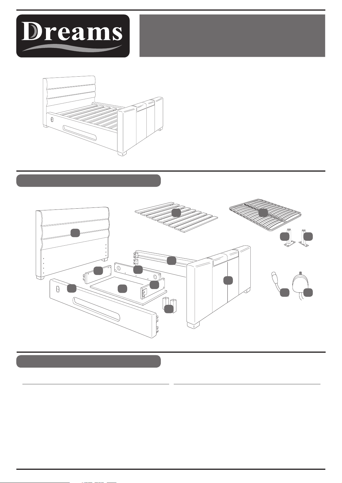
Parts Identification
12 13
1
3
5
7
8
2
9
6
4
Parts Checklist
Ref. Description Description
Qty
Ref.
P Q
11 10
Note:
Standard wooden slat frame (part 12)
Upgraded sprung slat frame (part 13)
Qty
1
2
3
4
5
6
7
8
Headboard
Footboard
Right Side Panel
Left Side Panel
Media Tray Base Panel
Media Tray Left Side Panel
Media Tray Back Panel
Media Tray Right Side Panel
1
1
1
9
10
11
1
1
1
1
1
12
13
P
Q
Page 1 of 7
Media Tray Support Legs
Power Lead
Aerial Lead
Wooden Slats
Metal Sprung Slat System*
Centre Support Leg*
Support Leg*
*Only supplied if upgraded sprung system chosen
2
1
1
1 Set
1 Frame
1
2
V2
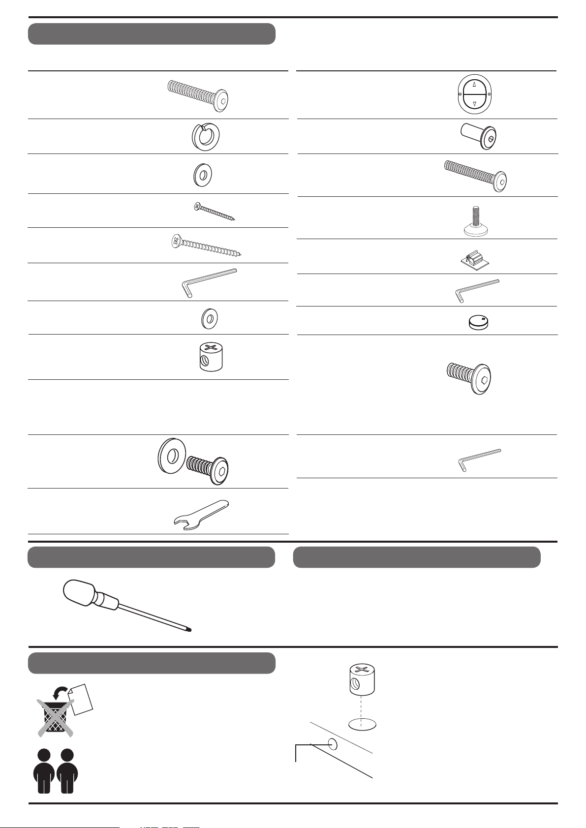
Fittings Checklist
Code Qty Description
A
B
C
D
E
F
G
Bolt (M8x30mm)
Spring Washer
Washer (17x8mm)
Screw (3x20mm)
Screw (5x50mm)
Allen Key (8mm)
Washer (16x6mm)
H
Barrel Nut
x22
x20
x20
x4
x13
x1
x6
x13
Code QtyDescription
I
Remote Switch
Sleeve Nut (M6x16mm)
J
Bolt (M6x40mm) x6
K
Adjustable Foot x2
L
Cable Clip
M
Allen Key (6mm) x1
N
R
Spare Battery - CR2016
UP
DOW N
Fitting ‘O’ is part of the fittings pack supplied
with the sprung slat frame.
x2
x6
x2
x3
TV INSTALLATION KIT
S
U
Screw-Washer set
Spanner x1
Additional Tools Required
Crosshead Screwdriver
x4
Bolt (M6x15mm)
O
T
Allen Key
Care & Maintenance
In the unlikely event of missing or damaged parts, please
contact the customer service team on 08442 920000.
When calling this number, please quote the part code
reference numbers shown in this leaflet, to properly
identify spare or replace men t parts.
x8
x1
General Hints & Tips
Please tetain your Assembly Instruction and
tools provided, for future use. Periodically
check that all bolts are still tight.
This
assembly requires two
people.
Intersecting
Hole
Page 2 of 7
fitting barrel nuts into
When
the
panels, ensure they are
fitted the correct way so the
hole is facing towards the
intersecting hole.
We recommend the bed is
assembled in the room it will
be located in.
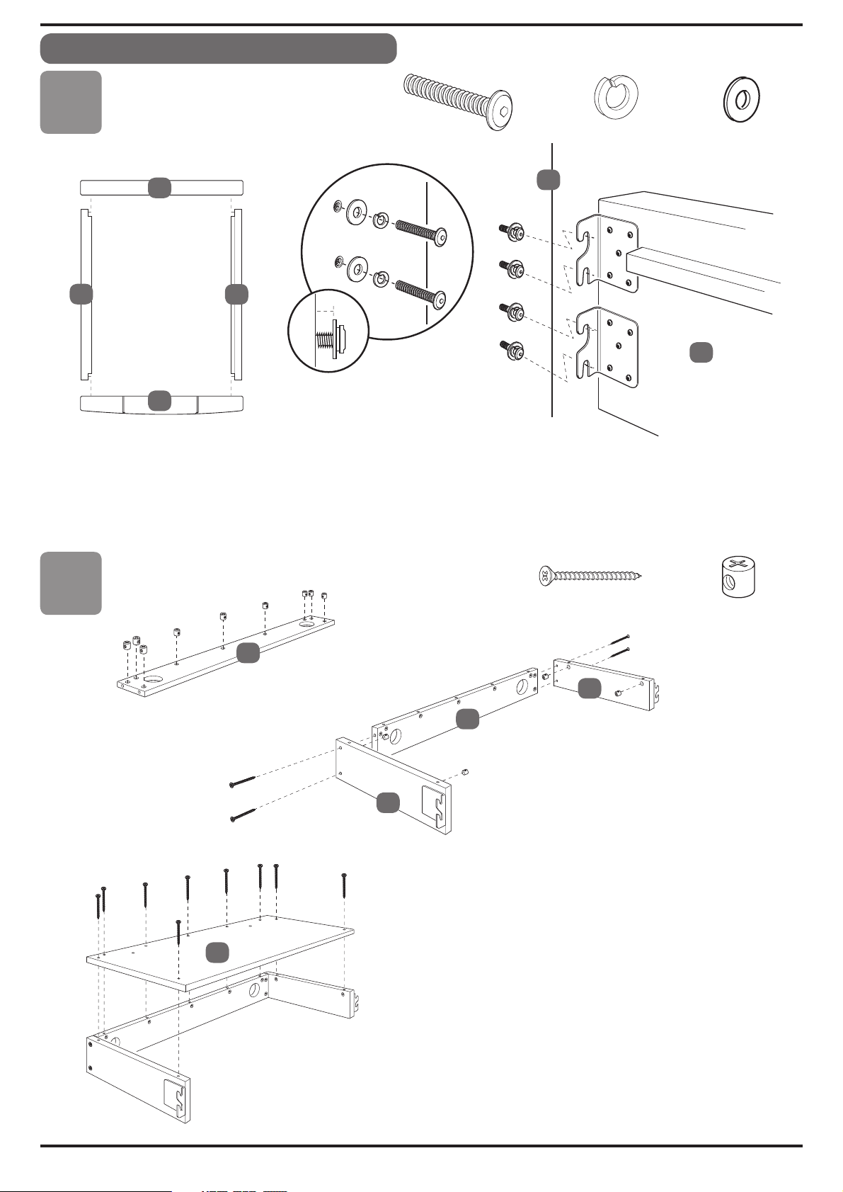
Bed Assembly
Stage
A
x16
B
1
1
4
2
Fit the bolts (A), spring washers (B), and flat washers (C) to the holes in the headboard and
footboard (1 & 2) as shown. Note: Do not fully locate the bolts, but leave 10mm protruding.
Fit the side panels (3 & 4) to the head and footboards locating the brackets behind the flat washers.
Once all four corners are located, fully tighten the bolts using the allen key (F).
3
10mm
1
x16
C
3
x16
Stage
2
E
7
6
7
8
Fit the barrel nuts (H), to the Media Tray back panel (7),
making sure the screw hole aligns with the intersecting
hole (see hints & tips section).
5
Fit the tray side panels (6 & 8), to the back panel (7)
using the screws (E) into the barrel nuts.
x13
H
x13
Fit barrel nuts (H) to the inside sides of the tray side
panels as shown.
Fit the tray base panel (5) using the screws (E) to
secure through into the barrel nuts previously fitted.
Page 3 of 7

Bed Assembly continued
Stage
3
A
9
Fit the adjustable feet (L) to the underside
of the tray support legs (9) screw into
Fit the support legs (9) to the underside of
the tray base panel using the bolts (A) to
secure. Fully tighten using the allen key (F).
9
9
x2
L
place.
x2
Stage
4
4
A
Push bolt (A) through spring washer (B) and flat washer (C),
Hold tray firmly against side rail (4) as shown and screw in x4 bolts.
When all screwed in place, tighten bolts 100%.
x4
B
x4
C
x4
Adjust the feet (L) so bottom of tray is level.
Page 4 of 7

Bed Assembly continued
Stage
5
D
1
x4
TV INSTALLATION KIT
I
UP
DOWN
TV Mounting Bracket
2
x2
S
x4
T
x1
I
Lid
D
WARNING
!
HAXARDOUS VOLTAGE
Contact mav cause
electric shock or burn
This unit is to be servied by
TV
trained personnel only.
1
2
HDMI 1 & 2
AC 220V ~ 240V
Power Socket
10
FOOTBOARD
2
2
Wall Socket
Aerial
Aerial Socket
11
Television Installation
Before fixing the slats to the Bedstead, please follow the television installation instructions below
1.
Connect the power cable (10) and aerial cable (11) to the sockets located at the bottom of the footboard (2)
.
and then connect to your wall sockets. Connect media using the HDMI sockets (HDMI cables not supplied).
Raise the TV lift by pressing one of the UP buttons located on either side rail of the bed.
2.
3.
Unpack your television and remove the four ‘VESA’ screws from the back of the TV or from the TV package.
Connect the television to the TV mounting bracket using the screw-washer set (S).
4.
If necessary you can use the spanner to adjust the bracket up and down to align with the screw fixing points
on the back of the television.
Carefully tighten the screw (S) using the allen key (T) - the spanner & allen key can be found in the TV
installation kit, in the main hardware pack.
Connect the power and aerial cables to the television making sure the cables are not loose. If necessary use
5.
spare clips (M) to route cables safely.
6.
The television can now be operated following the manufacturers handbook.
7.
To lower the television back into the footboard, press one of the side rail DOWN buttons.
When DOWN button is pressed, TV will retract into footboard and turn off automatically at the bottom .
When UP button is pressed - TV rises and turns itself back on automatically.
S
T
TROUBLESHOOTING
1.
If your television does not operate please check all the power connections both to the wall and to the socket
on the footboard.
If you TV Lift does not operate, try both of the switches mounted on each side of the bed to check if both are
2.
NOT working. If only one operates change the batteries in the one not working - see following instructions.
3.
If either the television or TV Lift still fails to operate there may be a problem that can be checked by our
technicians. Call the Customer Services number for help and information - 08442 92000.
Care should be taken when connecting electrical items. If in any doubt over the connections
IMPORTANT
please consult a qualified electrician.
:
Page 5 of 7

Bed Assembly continued
Stage
6
Stage
6a
BED SLA
UPGRADE SPRUNG SLAT SYSTEM
T FIXING
12
12
12
K
Lay the set of slats (12) onto the metal
slat support rails, on each side of the bed.
Align the first and last slat with the
end of the rails, and secure in place
using the bolts (K), washers (G) and
sleeve nuts (J). Fully tighten using
the allen key (N).
Once ends are secure, fix two bolt sets
to centre slat, so all 6 sets are used.
K
x6
x4
G
J
G
x6
x6
x4
13
13
O
Q
Open the metal slat frame and lay face down on the working
surface.
P
Q
Fit the support legs (P & Q) to the positions shown, securing
with the bolts (O). Fully tighten using the allen key (N).
Carefully turn the slat frame over, and position onto the metal slat
support rails. Align the frame with the fixing holes at each
end of the rail and secure using just 4 sets of the bolts (K),
washers (G) and sleeve nuts (J). Fully tighten using the allen key (N).
Finally, please ensure that all bolts are fully tightened
before the bed is used.
EITHER 12 OR 13 WILL BE SUPPLIED - BOXED SEPARATELY.
x8
J
x4
13
13
Page 6 of 7

Changing the batteries in the remote switch
Battery specification : CR 2016 x3
Tool Requirement : Small Crosshead screwdriver.
Carefully follow these instructions to re-place the batteries;
Step 1: Remove screws (D) and take the switch (I) out of the side panel.
Step 2: Turn switch over & slide off the battery cover.
Step 3: Slide out the round case holding the batteries.
Step 4: From round case take out the three batteries noting
the way they are placed.
Change all three batteries taking care to make sure +
sides remains pointing upwards.
Re - insert into plastic case and slide back into position
in the switch. Make sure + side is upward touching the
+mark on the terminal.
Test the switch - you can do this outside the side panel of the bed.
When tested, re-place in side panel the correct way round.
Note, the remote switch and controller have a self protection (A) & child-safety feature (B).
(A) If buttons are pressed in quick succession, you may need to press UP or DOWN button twice to operate the
motor of the TV Lift... this is normal and is nothing to be concerned about - it is a feature to protect the controller
system.
(B) If
TV lift has been down in the rest position for a few minutes, it will be necessary to press DOWN button once,
THEN press UP button TWICE, to raise the TV lift. Pressing the button in this sequence “wakes” the controller from
child safety mode, then it will operate normally.
1
2
3
4
I
D
Page 7 of 7
 Loading...