


Dreambox DM7000S
User’s Manual
Digital satellite receiver for free and encrypted DVB-TV Programs
with optional digital hard disk recording.
Communication-Port
PCMCIA-Slot for CI-CA-Modules
Internal hard disk
Compact Flash Slot
LC-Display
2 Smartcard Readers
Linux OS
Rev.1.0_rel.1.07.4_dd_eng

1. Contents
1. Contents................................................................................................................................................- 2 -
2. Views.....................................................................................................................................................- 4 -
Description Frontview............................................................................................................................- 5 -
3.
CI-Slot ...................................................................................................................................................- 5 -
3.1.
Compact Flash Slot...............................................................................................................................- 5 -
3.2.
3.3. Smartcard Reader.................................................................................................................................- 5 -
Remote receiver....................................................................................................................................- 5 -
3.4.
Channel up/down ..................................................................................................................................- 5 -
3.5.
LC-Display.............................................................................................................................................- 5 -
3.6.
3.7. Power-Button ........................................................................................................................................- 5 -
Description Rear view ...........................................................................................................................- 6 -
4.
Mainspower 230V / 50Hz ......................................................................................................................- 6 -
4.1.
TV Scart ................................................................................................................................................- 6 -
4.2.
4.3. VCR Scart .............................................................................................................................................- 6 -
HiFi-Amplifier.........................................................................................................................................- 6 -
4.4.
Analogue Audio (Cinch) ........................................................................................................................- 6 -
4.5.
Digital Audio (Toslink) ...........................................................................................................................- 6 -
4.6.
4.7. Communication Port (Ethernet 10/100MBit, RJ45) ...............................................................................- 6 -
Mini DIN Socket ....................................................................................................................................- 6 -
4.8.
USB Socket...........................................................................................................................................- 6 -
4.9.
Serial Socket (RS232C, Sub-D, 9-pin) ..................................................................................................- 6 -
4.10.
LNB In ...................................................................................................................................................- 6 -
4.11.
4.12. LNB Out ................................................................................................................................................- 6 -
Safety instructions.................................................................................................................................- 7 -
5.
Delivering ..............................................................................................................................................- 8 -
6.
Installation.............................................................................................................................................- 8 -
7.
8. Remote Control Overview .....................................................................................................................- 9 -
Important Notes about Condition.........................................................................................................- 10 -
9.
Remote Control Describtion ................................................................................................................- 11 -
10.
Dreambox switching on / off...............................................................................................................- 13 -
11.
12. Sleeptimer...........................................................................................................................................- 13 -
OSD-Main menu .................................................................................................................................- 14 -
13.
Infobar.................................................................................................................................................- 15 -
14.
Infobar - EPG (Electronic Program Guide)..........................................................................................- 16 -
14.1.
14.2. Infobar - Subservices ..........................................................................................................................- 16 -
Infobar - Audio Track...........................................................................................................................- 17 -
14.3.
Infobar - Plugins ..................................................................................................................................- 17 -
14.4.
Setup - OSD Language.......................................................................................................................- 18 -
15.
16. Setup - Time Zone...............................................................................................................................- 18 -
Setup - Time Correction ......................................................................................................................- 18 -
17.
Satellite Configuration.........................................................................................................................- 19 -
18.
Satfind.................................................................................................................................................- 19 -
19.
20. Motor Setup.........................................................................................................................................- 20 -
Automatic Transponder Scan..............................................................................................................- 21 -
21.
Automatic Multisat Scan......................................................................................................................- 22 -
22.
Manual Transponder Scan..................................................................................................................- 22 -
23.
24. Transponder Edit.................................................................................................................................- 23 -
Service Organising - Create new Bouquet ..........................................................................................- 24 -
25.
Service Organising - Add services to Bouquet....................................................................................- 25 -
26.
Service Organsing - Edit Bouquets .....................................................................................................- 26 -
27.
28. Common Interface...............................................................................................................................- 26 -
Parental Lock ......................................................................................................................................- 27 -
29.
Parental lock enable / disable .............................................................................................................- 27 -
29.1.
29.2. Setup lock enable / disable .................................................................................................................- 27 -
- 2 -

30. Services locking / unlocking ................................................................................................................- 28 -
A/V Settings ........................................................................................................................................- 29 -
31.
OSD Settings ......................................................................................................................................- 30 -
32.
32.1. Skin Setup...........................................................................................................................................- 30 -
Available Skins....................................................................................................................................- 31 -
32.2.
TuxText position..................................................................................................................................- 32 -
32.3.
Teletext - Software Decoder (TuxText) activating ...............................................................................- 32 -
33.
34. LCD Settings.......................................................................................................................................- 34 -
Expert Setup .......................................................................................................................................- 34 -
35.
Communication (Network, LAN Setup)................................................................................................- 35 -
35.1.
Communication (Network, WAN (DSL) Setup)....................................................................................- 36 -
35.2.
35.3. NGrab Streaming Setup......................................................................................................................- 36 -
Software Update over Internet ............................................................................................................- 37 -
35.4.
Software Update manual.....................................................................................................................- 37 -
35.5.
Remote Control ...................................................................................................................................- 37 -
35.6.
36. Hard Disk - Assembly Instructions.......................................................................................................- 38 -
Hard Disk Setup ..................................................................................................................................- 47 -
37.
Recording a movie (spontaneous recording).......................................................................................- 47 -
38.
Viewing/deleting/renameing recorded movies.....................................................................................- 48 -
38.1.
39. Recording a movie (Timer recording)..................................................................................................- 49 -
Timeshift..............................................................................................................................................- 50 -
40.
Timer...................................................................................................................................................- 50 -
41.
Information - Streaminfo / About .........................................................................................................- 51 -
42.
DreamUp - Software upgrade .............................................................................................................- 52 -
43.
43.1. DreamUp - Preparing DreamUp..........................................................................................................- 53 -
DreamUp - Establish a Connection .....................................................................................................- 54 -
43.2.
DreamUp - Backup Software...............................................................................................................- 56 -
43.3.
DreamUp - Erasing Software ..............................................................................................................- 58 -
43.4.
43.5. DreamUp - Flashing Software.............................................................................................................- 60 -
Dreambox resetting to factory defaults (flash erase)...........................................................................- 63 -
43.6.
Dreambox Hardware reset ..................................................................................................................- 63 -
44.
Technical Data ....................................................................................................................................- 64 -
45.
46. Contact & Support Information............................................................................................................- 66 -
Setup-TV-Mode...................................................................................................................................- 67 -
47.
Program sequence..............................................................................................................................- 67 -
47.1.
48. TV - Codelist .......................................................................................................................................- 68 -
Notice:
The Dreambox DM7000S is CE certified and fulfills all requirements of the EU-Standards.
Alterations are subject to change without notice. E. & O. E.
Dream-Multimedia-Tv and Dreambox DM7000S are registered trademarks of
Dream-Multimedia-Tv GmbH, Pierbusch 24 D-44536 Lünen Germany
Issued: March 2004 Rev.1.0
Software: Release 1.07.4
www.dream-multimedia-tv.de
- 3 -
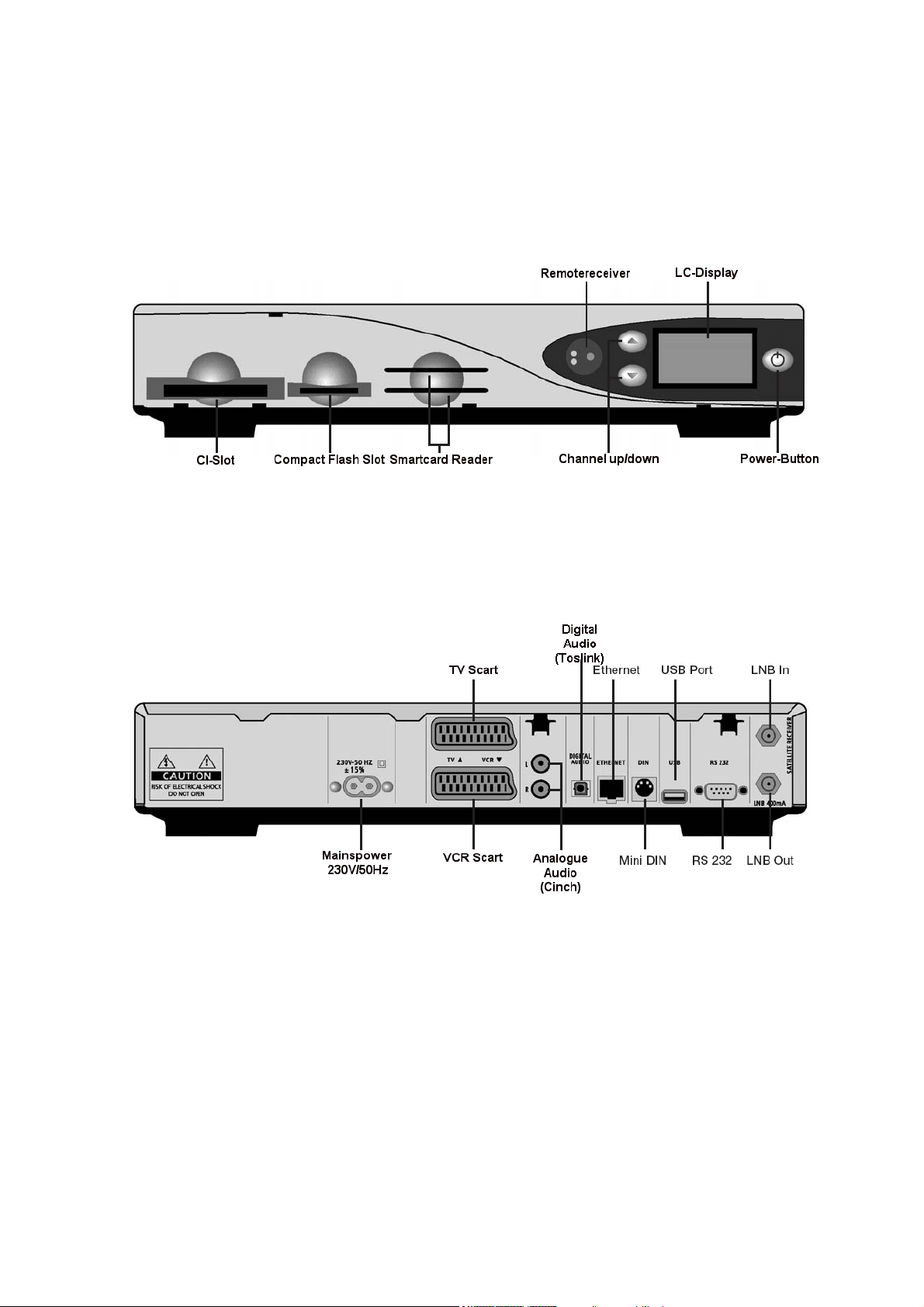
2. Views
Frontview
:
Rear view:
- 4 -

3. Description Frontview
3.1. CI-Slot
Plug in here any CI- or CA-Module of your choice.
3.2. Compact Flash Slot
The Compact Flash Slot is mentioned to hold a Compact Flash Module. If you want to use a CFModule, shut down your Dreambox using the Deep-Standby-Mode. Plug in carefully your CF-Module
into the Compact Flash Slot. The CF-Module is recognised by the System as a hard disk, we
recommend to disable the internal hard disk for proper usage. Power back on the Dreambox. To
access the Compact Flash Module, choose the File-Mode in the OSD-Main menu. Sometimes it is
nessesary to format your CF-Module via the OSD-Menu.
See passage Hard Disk Setup.
3.3. Smartcard Reader
Plug in your Dreamcrypt Smartcard with the gold chip face downwards and inwards into one of the
Smartcard Reader.
Dreamcrypt is a trademark of Dream-Multimedia-Tv GmbH.
3.4. Remotereceiver
The Remote receiver receives the infrared signals from the Dream Remote Control.
3.5. Channel up/down
The channel buttons at the Front of your Dreambox switch the TV or Radio channels up and down. To
initialize the “Flash Erase” hold down the channel up button.
See passage Dreambox resetting to factory defaults (flash erase).
3.6. LC-Display
The LC-Display shows all major Information for the selected service.
3.7. Power-Button
The Power-Button turns your Dreambox off and on.
- 5 -

4. Description Rear view
4.1. Mainspower 230V / 50Hz
Plug in the Power cord into the Mainspower socket. The Powerplug remains only in its recommened
sockets 230V / 50Hz.
4.2. TV Scart
Connect your TV with an appropiate Scartcable to your Dreambox.
4.3. VCR Scart
Connect your VCR with an appropiate Scartcable to your Dreambox. Remember, the VCR Scart is
not
designed to record a Videosignal from the VCR.
4.4. HiFi-Amplifier
Connect your HiFi-Amplifier either to the analogue audio R/L (RCA/Cinch) or digital audio (Toslink)
socket.
4.5. Analogue Audio (Cinch)
Connect your Dreambox with an appropiate RCA/Cinch cable to your HiFi-Amplifier (e.g. AUX or Tape
socket).
4.6. Digital Audio (Toslink)
Connect your Dreambox with an appropiate optical (Toslink) cable to your HiFi-Amplifier or DSP. The
Dreambox provides sample rates from 16, 22.05, 24, 32, 44.1, 48 kHz. The AC3 signal is also
available at this socket, if the selected channel transmits Dolby Digital signals.
4.7. Communication Port (Ethernet 10/100MBit, RJ45)
The Communication Port is an Ethernet socket. Used to communicate with the Dreambox via HTTP,
FTP, NFS, Telnet und Samba to access your recorded movies or to upload channel lists. This socket
is also mentioned to update the Operation system. Please connect an appropiate patchcable.
See passage DreamUp - Software upgrade.
4.8. Mini DIN
The Mini DIN Port is mentioned for external I2C Rotorsignals and provides Signals for external IR
Devices.
4.9. USB Port
The USB Port is designed for USB 1.2 compatible Devices. The amount of provided USB devices
depends on the installed image (Software) and is still under Development.
4.10. Serial Port (RS232C, Sub-D, 9-pin)
The Serial Port is mentioned to update the Operation system. Please connect a serial nullmodem
cable here. See passage DreamUp - Software upgrade.
4.11. LNB In
Connect the coaxial cable from your LNB here. Please switch the power off from the the Dreambox
first.
4.12. LNB Out
Connect an analogue receiver here. Remember to shutdown your Dreambox into Deep-StandbyMode, if you wish to view analogue TV.
- 6 -

5. Safety instructions
Please read the safety instructions completely and carefully, before using the Dreambox. The
Manufacturer takes no responsibility of incorrect handling of the Dreambox.
- Allow enough space around the Dreambox for sufficient ventilation.
- Do not cover the Dreambox’s ventilation openings with items such as newspapers, tablecloths,
curtains etc.
- Do not expose the Dreambox to dripping or splashing liquids.
- Do not place naked flame sources, such as lighted candles, on the Dreambox.
- Do not place any objects filled with liquids, such as vases, on the Dreambox.
- Do not connect or modify cables when the Dreambox is plugged in.
- Do not remove the cover. Risk of electric shock!
- Do not stick any metallic items into the slots or ventilation openings.
- The installation of a hard disk is only allowed by skilled personal or your local dealer.
- Please note that the only way to isolate the Dreambox completely from the mains power supply is
to unplug the mains powercord!
- If you do not use your Dreambox for a longer time, please diconnect it from the mains power.
- Please disconnect your Dreambox from the mains power during thunder or heavy storms.
- Connecting to the dish (LNB):
Disconnect the mains powercord before connecting or disconnecting the coaxial cable.
- Connecting to the TV or VCR:
Disconnect the mains powercord before connecting or disconnecting the scartcable.
- Disconnect the mains powercord if the powercord is damaged.
- Disconnect the mains powercord if the Dreambox gets in contact with moisture or moisture has
penetrated inside.
- Disconnect the mains powercord if you see any damage to the casing.
- Grounding:
The dish must be grounded.
The grounding system must match SABS 061.
- Cleaning:
Disconnect the mains powercord before cleaning the cover. Use a slightly damp cloth without
cleaning agents.
- Connect the Dreambox only to suitable sockets 230V/50Hz. Do not allow overloads to occur.
WARNING!
Modifications and changes to the Dreambox leads to loss of warranty.
We recommend the installation of a hard disk by your local dealer.
Unskilled installtion of a hard disk leads to loss of warranty.
- 7 -

6. Delivering
The box of your DM7000S should contain the following items:
1 receiver Dreambox 7000S
1 powercord
1 remote control
1 user’s manual (newest release @ http://www.dream-multimedia-tv.de
2 batteries (1,5V Mignon / AA / LR6)
2 hard disk mounting racks (are premounted)
1 IDE cable
1 molex powercord for the hard disk
optional parts:
1 wireless keyboard
7. Installation
- Insert 2 AA (1,5V) batteries, taking care to observe the + and - markings indicated inside, into the
Remote Control.
- Before using the Dreambox, please read the safety instructions.
- Connect the LNB with an appropiate coaxial cable to LNB In at your Dreambox.
- Connect the Dreambox with an appropiate scart cable to your television screen.
- Plug in the mains powercord into the mains power socket 230V/50Hz.
- If you are useing a switchable power socket please shutdown your Dreambox into deep standby
before switching off the power socket.
- If you turn on your Dreambox for the first time, you will see the setup wizzard. The setup wizzard
will guide you through the first time installation. You will be asked for your tv norm, the regional
settings and your language. Please choose and follow the instructions on the screen.
- Please notice that the videoformat is set by default to CVBS (FBAS).
See passage A/V Settings.
)
- 8 -
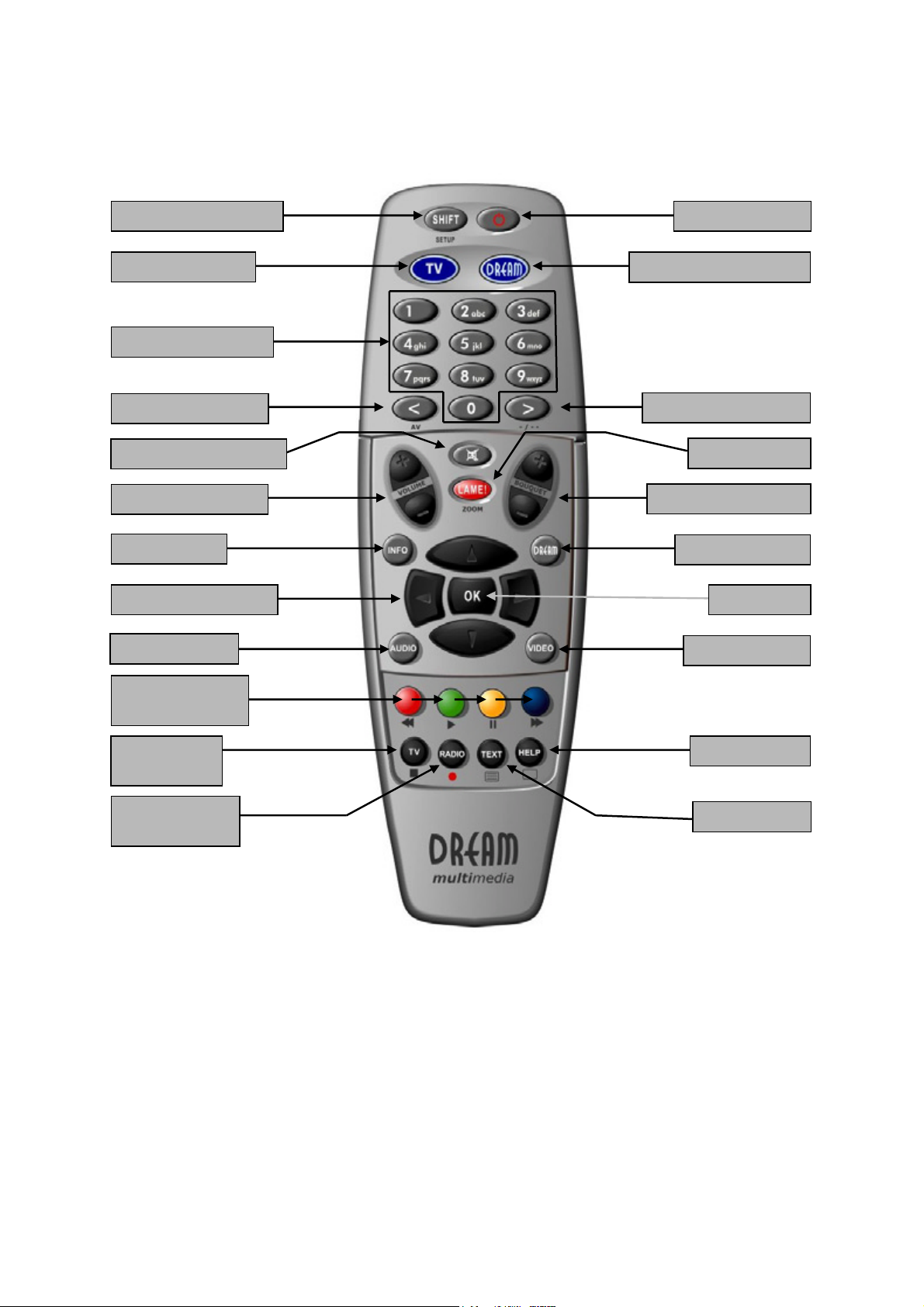
8. Remote Control Overview
V
V
V
SHIFT-Setup-Button
TV-Mode-Button
Numeric-Keyboard
Arrow-Left-Button
olume-Mute-Button
olume +/- Button
INFO-Button
Navigation-Buttons
AUDIO-Button
Option-Buttons
(PVR-Mode)
TV-Button
(PVR-Mode)
RADIO-Button
(PVR-Mode)
POWER-Button
DREAM-Mode-Button
Arrow-Right-Button
LAME-Button
Bouquet +/- Button
DREAM-Button
OK-Button
IDEO-Button
HELP-Button
TEXT-Button
- 9 -
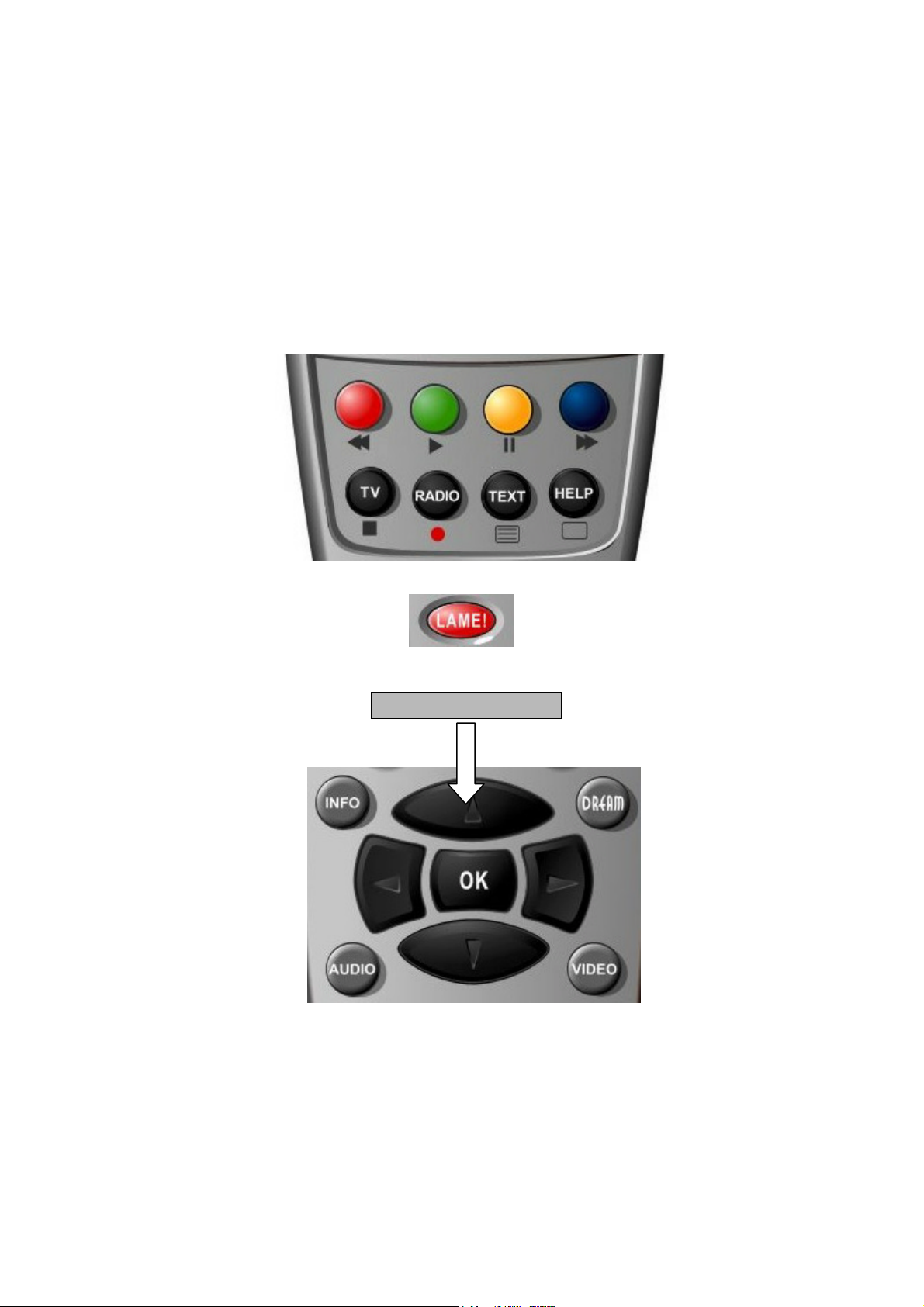
9. Important Notes about Condition
All Functions of the Dreambox will be controlled via an OSD-Menu (On-Screen-Display). This makes
the Condition of the Dreambox very easy for you. Possible Options are assigned by four coloured dots
or beams (red, green, yellow, blue) in the OSD-Menu and are activateable with the Option-Buttons on
the Remote Control.
Depending on the chosen Menu, the Options do change and are explained via the Help-Button on the
Remote Control.
The Option-Buttons are assigned with more than one Function. As you can see, under the OptionButtons, TV-Button and RADIO-Button, are Symbols. These Symbols are for the Condition in the
PVR-Mode (Private Video Recording). To activate or deactivate the PVR-Mode press the VIDEOButton. You will notice, that the Infobar changes its appearience. You will find more Information about
recording at passage Recording a movie (spontaneous recording)
All Menus and Servicelists are
closed with the LAME-Button.
The LAME-Button is similar to
the EXIT function.
The Condition of the OSDMenus will be performed with
the Navigation-Buttons on your
Remote Control.
Navigation-Buttons
If you want to enter a Menu
press the OK-Button.
- 10 -

10. Remote Control Describtion
SHIFT-Setup-Button
This Button is used to program the Remote Control for a TV Device.
See Passage Setup-TV-Mode
POWER-Button
This Button switches your Dreambox on or off.
See passage Dreambox switching on / off.
TV-Mode-Button
This Button turns the Remote Control into TV-Mode. The TV-Mode-Button flashes shortly, if you press
this or any other Button in this Mode. The Remote Control controls now your TV.
DREAM-Mode-Button
This Button turns the Remote Control into Dream-Mode. The Dream-Mode-Button flashes shortly, if
you press this or any other Button in this Mode. The Remote Control now controls the Dreambox.
Numeric-Keyboard
Enter a Service number direktly over the Numeric-Keyboard. The Service numbers are on the left Side
of the Servicelist.
In the OSD-Mainmenu are numbers shown in front of the Option or Function, in this case you can
enter the desired number to access the Option or Function directly without moving the Cursorbeam to
it.
Arrow-Left-Button
These Buttons enable to jump back- or forwards through the Playlist. The Playlist contains the last
chosen Services and Movies, that have been selected.
Once having opened the Servicelist, you are able to jump at the Beginning or the End of the
Servicelist or to the next Marker.
Volume-Mute-Button
This Button mutes the Volume. A crossed Speaker Symbol will appear on the TV Screen. Pressing it
again or the Volume +/- Buttons, brings the Audio back.
LAME-Button
This Button exits all Menus and aborts Operations. It’s the same as EXIT.
Volume +/- Button
These Buttons increase (+) or decrease (-) the volume.
Bouquet +/- Button
These Buttons switch through the Bouquets forwards (+) and backwards (-).
INFO-Button
This Button shows the EPG Informations. Pressing this Button twice, shows the StreaminformationMenu.
Arrow-Right-Button
- 11 -

Navigation-Buttons
These Buttons control the Cursor beam inside the Menus to reach the desired Option or Function.
OK-Button
This Button shows the Infobar if no OSD-Menu is shown. This button enters a chosen OSD-Menu
Option or Function.
DREAM-Button
This Button shows the OSD-Mainmenu. If a Servicelist is opened, press this Button to enter the
Service-Menu.
AUDIO-Button
The AUDIO-Button shows the available Audio-Tracks of the selected Service.
VIDEO-Button
This Button activates or deactivates the PVR-Mode. By pressing this Button a couple of times, if a
Servicelist is opened, it changes the View of the Servicelist.
Option-Buttons
These Buttons activate the shown Options. They also control the PVR functions in PVR-Mode.
TV-Button
This Button activates the TV-Mode. It also keeps the Stop-Funktion in PVR-Mode.
HELP-Button
This Button brings up the Help menu.
RADIO-Button
This Button activates the RADIO-Mode. It also keeps the Record-Function in PVR-Mode.
TEXT-Button
This Button activates the Teletext - Sofware Decoder. If a Servicelist is opened, this Button jumps
directly to the File-Mode.
- 12 -
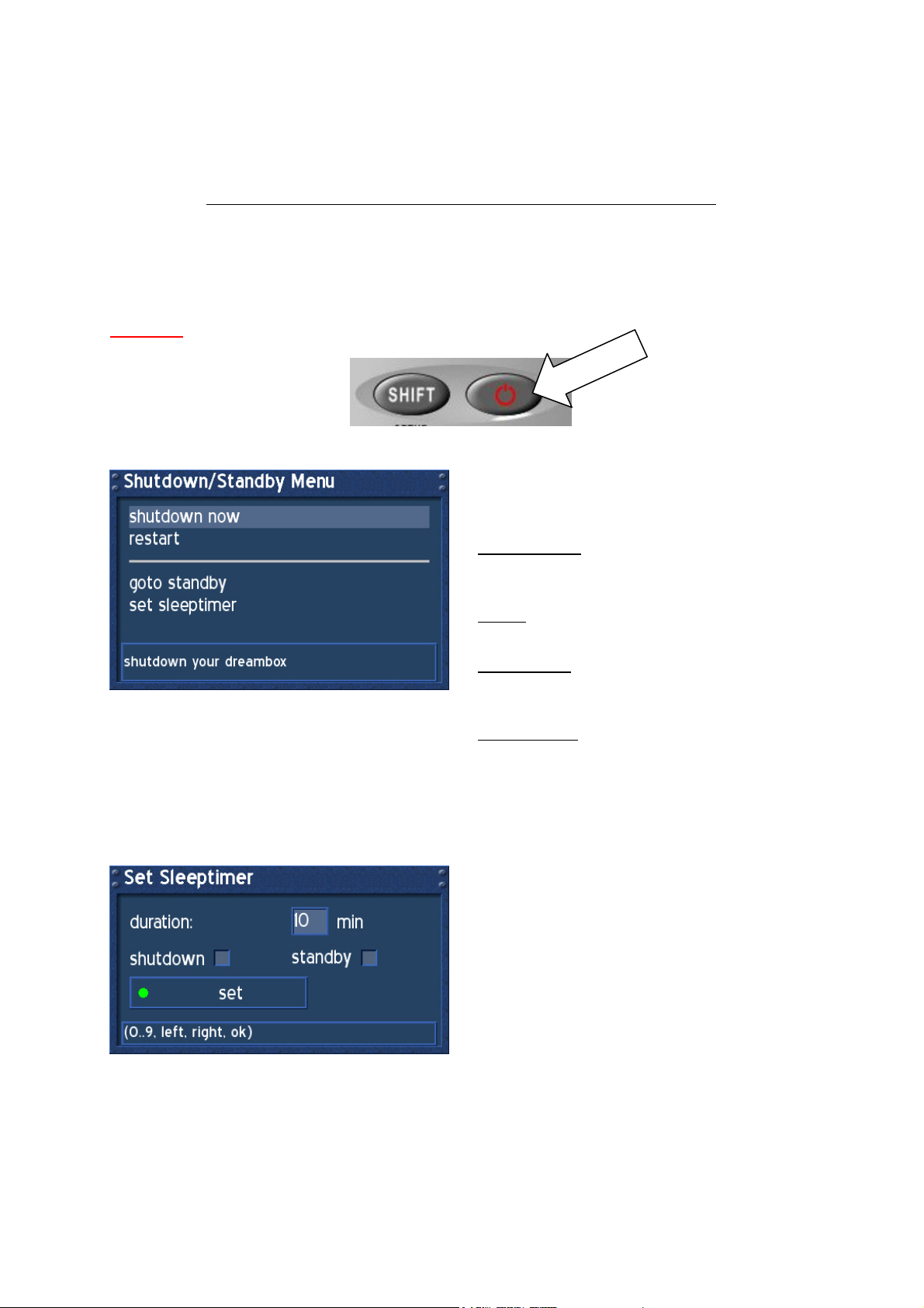
11. Dreambox switching on / off
Use the Power-Button to switch the Dreambox on or off. The Dreambox has two different StandbyModes. A Standby-Mode and a Deep-Standby-Mode. Unplug the Mains powercord to make the
Dreambox completely powerless.
The Power-Button only works if no OSD-Menu is shown on the TV screen!
Press the Power-Button once to switch the Dreambox into Standby-Mode. The actual Time appears
on the LC-Display.
Press the Power-Button for at least 5 seconds, to shut down the Dreambox into Deep-Standby-Mode,
or choose in the OSD-Mainmenu the option (9) Shutdown. All settings will be saved.
Attention: Timer and Sleeptimer only work in Standby-Mode.
Press the Power-Button for at least 3 seconds. The Shutdown / Standby Menu appears.
Use the Navigation-Buttons up and down to
choose an option. Press the OK-Button to
activate.
shutdown now:
The Dreambox shuts down into Deep-StandbyMode. The LC-Display shows no information.
restart:
The Dreambox restarts the Operationsystem.
goto standby:
The Dreambox shuts down into Standby-Mode.
The LC-Display shows the actual Time.
set sleeptimer:
See passage Sleeptimer.
12. Sleeptimer
Press the Power-Button for at least 3 seconds, select “set sleeptimer” to enter this menu.
Define a max. duration of 240 minutes. Define if
the Dreambox should shutdown or should go
into standby by setting a check into one of the
checkboxes beside shutdown and standby with
the OK-Button.
Press the green Option-Button to set
Sleeptimer.
- 13 -
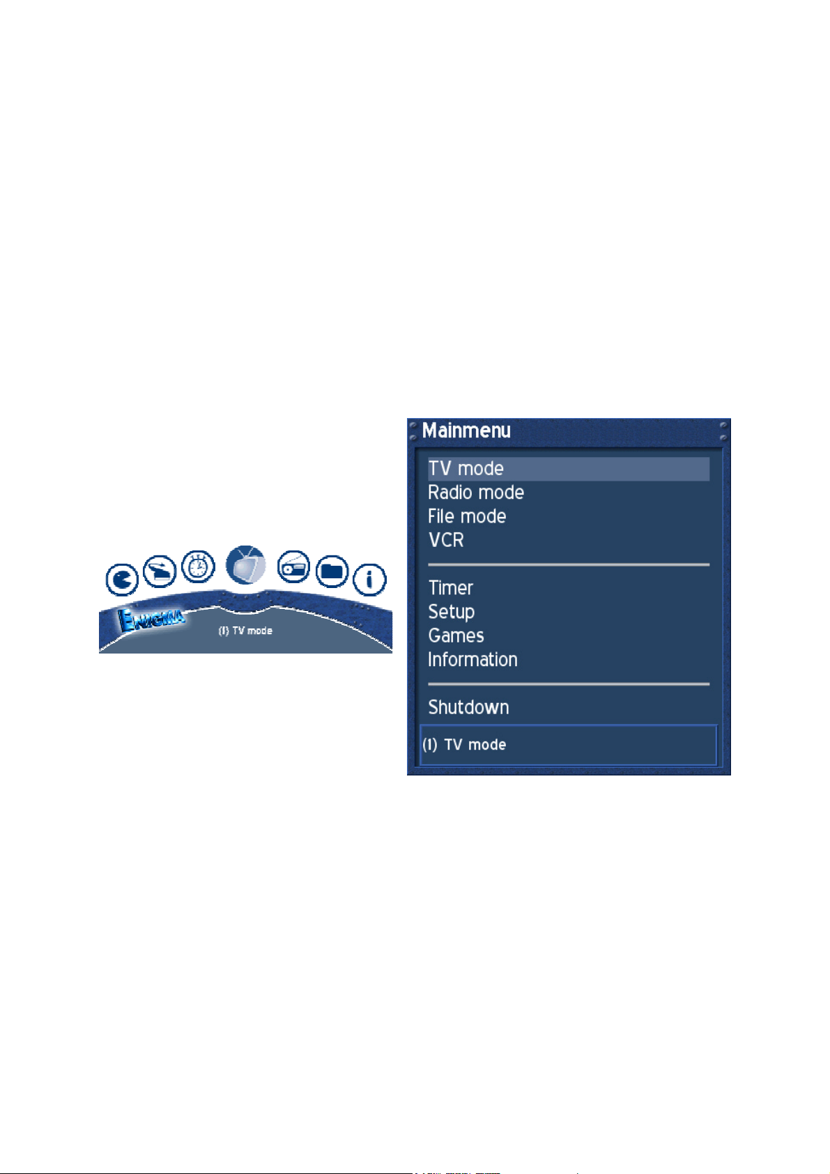
13. OSD-Mainmenu
If no OSD-Menu is shown on the tv screen, the DREAM-Button enters the OSD-Mainmeu.
Through this OSD-Mainmenu it is possible to activate the main options and functions. Use ether the
Navigation-Buttons followed by the OK-Button or press the desired number to enter the Option or
Function.
To change the view of the OSD-Mainmenu go to (6) Setup -> (3) System Settings -> (4) OSD Settings
and check the checkbox “Show Mainmenu like Listbox”. Exit all menus and reenter the OSDMainmenu.
(1) TV Mode
(2) Radio Mode
(3) File Mode
(4) Information
(5) Shutdown
(6) Setup
(7) Games
(8) VCR
(9) Timer
1. TV Mode
2. Radio Mode
3. File Mode
4. VCR
5. Timer
6. Setup
7. Games
8. Information
9. Shutdown
- 14 -
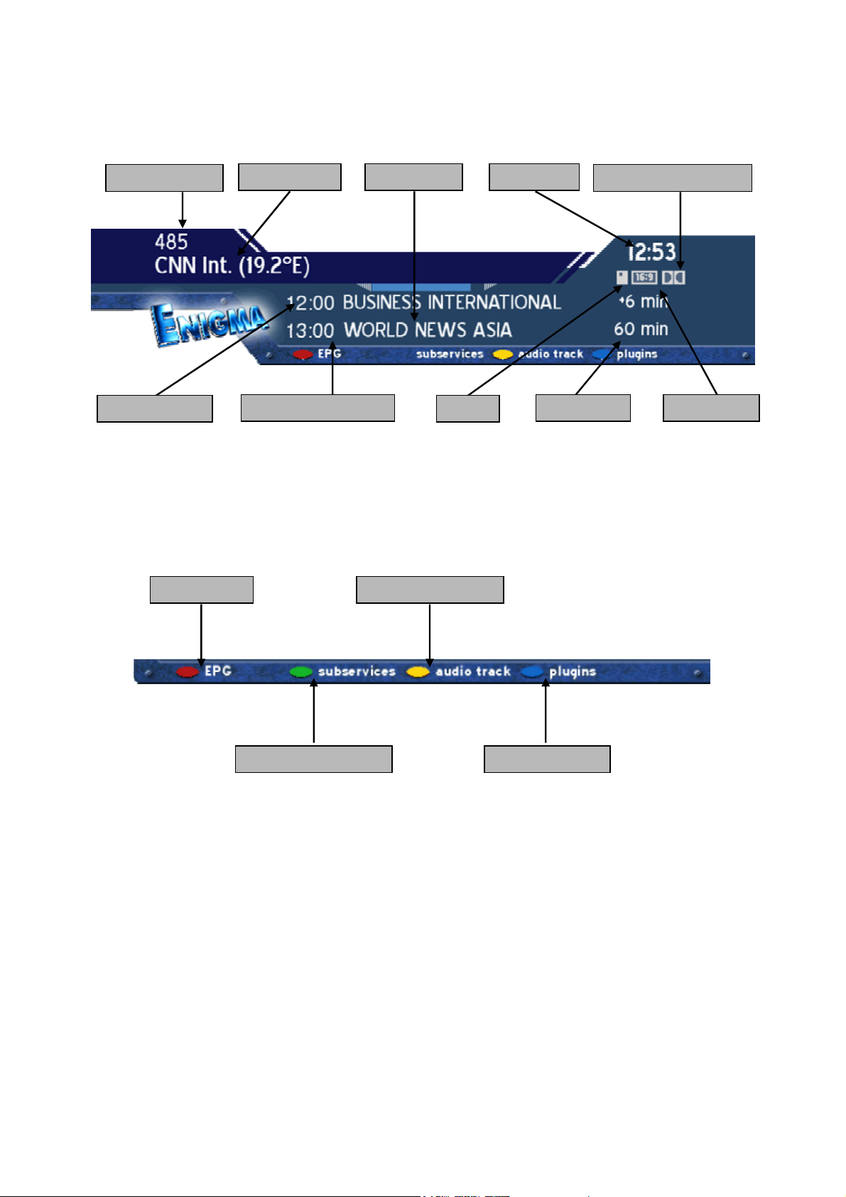
14. Infobar
The Infobar appears and disappears by pressing the OK-Button once, if no OSD-Menu is shown on
your tv screen. The Infobar shows all nessesary Information about the selected Service.
Channelnumber
Channelname
Actual TimeRemain Time
Dolby Digital Program
Actual Program
Upcomming Program
Crypted
Overall Time
Aspect Ratio
„Crypted“ appears orange, if the transmitted Service is crypted.
„Aspect Ratio“ appears orange, if the Service is transmitted in 16:9, the usal Aspect Ratio is 4:3.
„Dolby Digital Program“ appears orange, if the Service is transmitted with Dolby Digital
Audiostream.
EPG available
Audiotrack available
Subservices available
Teletext / Plugins
Attention: During activated PVR-Mode, the Option-Buttons control the PVR-Functions.
See passage Record a movie (spontaneous recording).
- 15 -
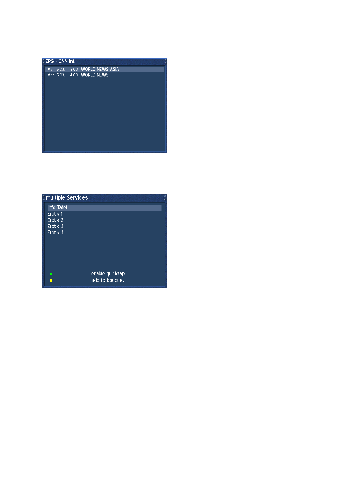
14.1. Infobar - EPG (Electronic Program Guide)
The red dot in the Infobar appears if the selected program transmits EPG informations.
Press the red Option-Button to enter the EPG.
Press the OK-Button to view detailed Information.
Press the LAME-Button to exit this menu.
14.2. Infobar - Subservices
The green dot in the Infobar appears if the selected program provides Subservices.
Press the green Option-Button to enter the menu
„multipile services“.
Use the Navigation-Buttons up and down to choose
a service. Press the OK-Button to enter the service.
enable quickzap:
Press the green Option-Button to enable the
quickzap mode. You can now choose a multipile
Service using the Navigation-Buttons left or right
without entering this menu. Press the green OptionButton to bring up this menu and press the green
Option-Button again to deactivate the quickzap
mode.
add to bouquet:
Press the yellow Option-Button to add the selected
Service to a Bouquet of your choice. See passage
Service Organising.
- 16 -
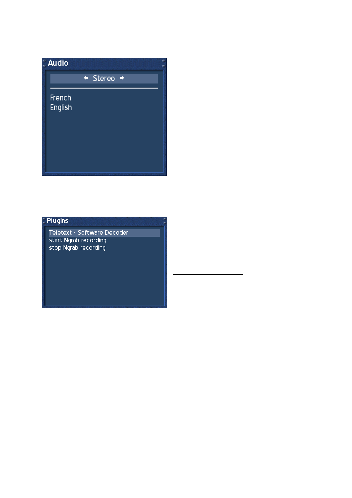
14.3. Infobar - Audio Track
The yellow dot in the Infobar appears if the selected Service transmittes multipile Audio-Tracks.
Use the Navigation-Buttons left or right to choose
the different Audio-Modes, Left-Mono, Stereo,
Right-Mono. Press the OK-Button to activate.
Use the Navigation-Buttons up or down to choose
another Audio-Language. Press the OK-Button to
activate.
14.4. Infobar - Plugins
The blue dot in the Infobar appears permanently
Use the Navigation-Buttons up or down to choose a
Plugin. Press the OK-Button to activate.
Teletext - Software Decoder:
This Option activates the Teletext - Software
Decoder. See passage Teletext - Software Decoder
(TuxText) activating.
start/stop Ngrab recording:
These Functions are still under development. They
are used to record a Service over the Network.
- 17 -
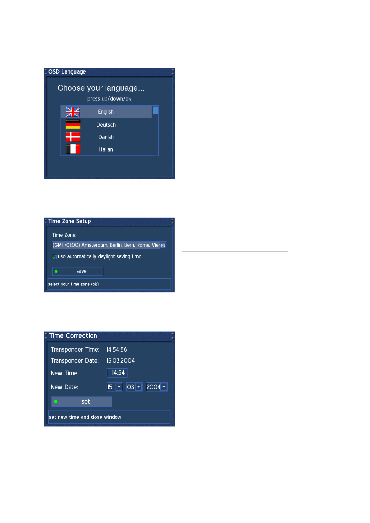
15. Setup - OSD Language
Press the DREAM-Button to enter the OSD-Mainmenu.
Go to (6) Setup -> (3) System Settings -> (5) OSD Language.
Use the Navigation-Buttons up or down to choose
your language. Press the OK-Button to activate. Exit
all menus and reenter.
16. Setup - Time Zone
Press the DREAM-Button to enter the OSD-Main menu.
Go to (6) Setup -> (3) System Settings -> (1) Time Settings -> (1) Timezone Configuration.
Press the OK-Button to open the Dropdownlist. Use
the Navigation-Buttons up or down to search for
your Time Zone. Press the OK-Button to select.
use automatically daylight saving time:
Check or uncheck the Checkbox with the OKButton. If checked, the Time will be automatically
adjusted for daylight saving changes.
Press the green Option-Button to save.
17. Setup - Time Correction
Press the DREAM-Button to enter the OSD-Mainmenu.
Go to (6) Setup -> (3) System Settings -> (1) Time Settings -> (2) Time Correction.
When entering this menu, please wait a second.
The Dreambox tries to get the actual Time. The
Transponder Time and Date will be automatically
updated.
If this fails, enter the new Time and Date manually.
Press the green Option-Button to set the new Time
and Date.
- 18 -
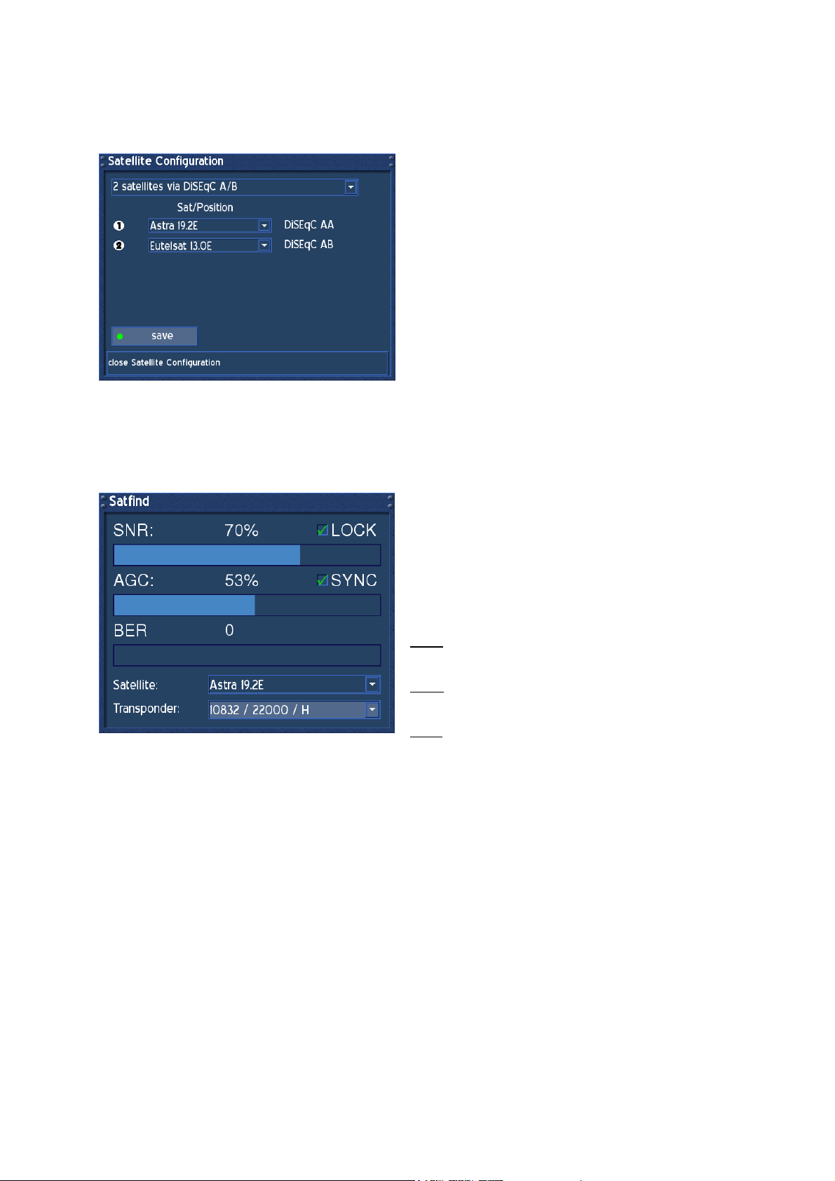
18. Satellite Configuration
Press the DREAM-Button to enter the OSD-Mainmenu.
Go to (6) Setup -> (2) Service Searching -> (1) Satellite Configuration.
Navigate to the upper Dropdownlist and choose
your appropiate Satellite Configuration and press
the OK-Button. Choose your Satellites the Dish is
adjusted to and press the green Option-Button to
save configuration.
This Configuration might differ from yours.
19. Satfind
Press the DREAM-Button to enter the OSD-Main menu.
Go to (6) Setup -> (2) Service Searching -> (2) Satfind.
Choose from the lower Dropdownlists your preferred
satellite and transponder.
Adjust the Dish towards the desired satellite until
you have a high value on the Signal strength AGC
and on the Signal quality SNR indicator. The BER
should always indicate a value of zero if the Satellite
is locked and synced.
SNR: Signal to Noise Ratio
This Indicator shows the Quality of the Signal.
AGC: Automatic Gain Control
This Indicator shows the Strengh of the Signal.
BER: Bit Error Rate
This Indicator shows the Errors Rate of the Signal.
- 19 -
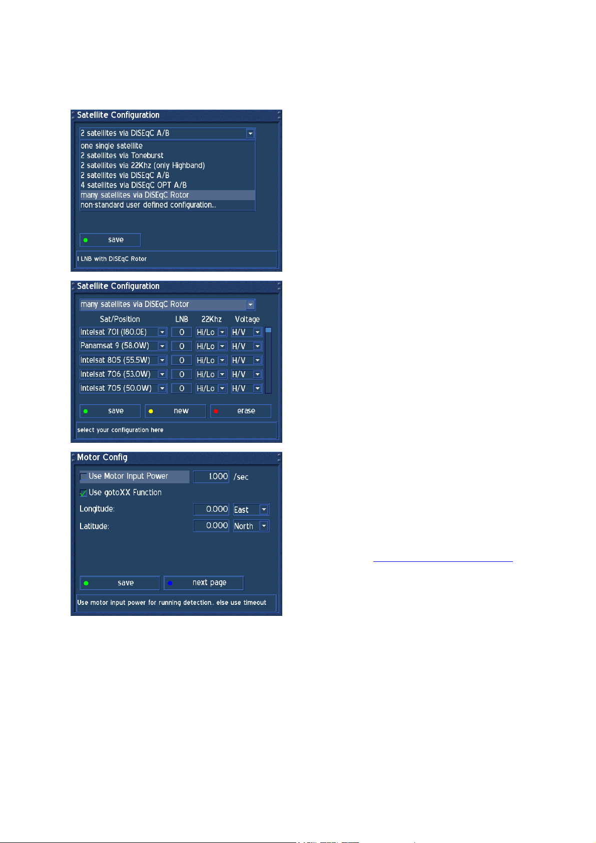
20. Motor Setup
Press the DREAM-Button to enter the OSD-Mainmenu.
Go to (6) Setup -> (2) Service Searching -> (3) Motor Setup.
Before proceeding with the Motor Setup refer to
passage Satellite Configuration and choose from
the upper Dropdownlist “many satellites via DiSEqC
Rotor” and press the OK-Button, if you setup a
Motor for the first time.
All possible satellites will be listed. Press the green
Option-Button to save this configuration.
After saving the Configuration, choose (3) Motor
Setup from the Menu Service Searching and press
the OK-Button. The Menu Motor Config appears.
Refer to the Rotors Manual for correct values
degrees/second. If unsure, set a check in front of
“Use Motor Input Power” and enter the maximum
current the Motor is using for turning to the Dish.
Visit the Website http://www.heavens-above.com to
figure out your geographical location. Enter the
values for Longitude and Latitude and press the
green Option-Button to save.
Proceed to passage Automatic Multisat Scan.
- 20 -
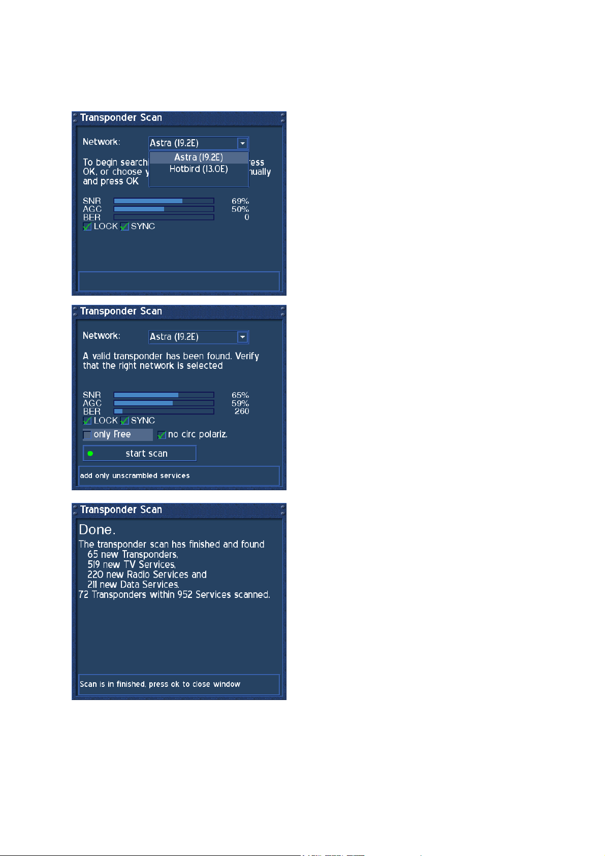
21. Automatic Transponder Scan
Press the DREAM-Button to enter the OSD-Main menu.
Go to (6) Setup -> (2) Service Searching -> (5) Automatic Transponder Scan.
The Automatic Transponder Scan scans one
satellite after one which is configured.
Select the first satellite to scan and press the OKButton.
Now choose to scan only Free services or not by
setting a check or not. If your LNB is not a C-Band
LNB, then let the check in the Checkbox in front of
“no circ polariz.”
Press the green Option-Button to start scan.
This window appears after scanning the satellite.
Press the OK-Button to proceed to the next satellite
scan.
- 21 -
22. Automatic Multisat Scan
Press the DREAM-Button to enter the OSD-Mainmenu.
Go to (6) Setup -> (2) Service Searching -> (6) Automatic Multi Scan.
The Automatic Multisat Scan is recommened for
scanning all configured satellites at once.
By pressing the OK-Button on each satellite a
couple of times, you set the scan method.
First: nothing, satellite will not be scanned
Second: all, services will be scanned
Third: only free, services will be scanned
Fourth: nothing, again
Press the green Option-Button to start scan.
This window appears after scanning the satellites.
Press the OK-Button and answer no to the next
question.
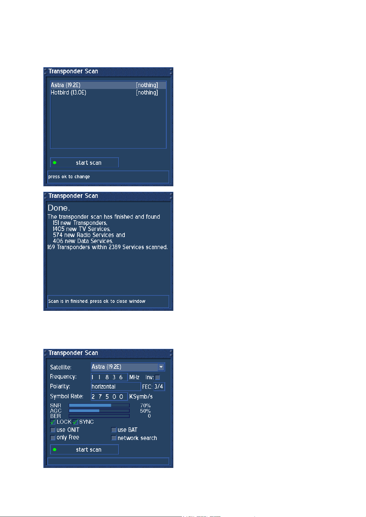
23. Manual Transponder Scan
Press the DREAM-Button to enter the OSD-Main menu.
Go to (6) Setup -> (2) Service Searching -> (7) Manual Transponder Scan.
The Manual Transponder Scan is recommened for
scanning a specific Transponder that has not been
found during Automatic Transponder Scan. New
services will be added to the Servicelist.
Press the OK-Button on the upper Dropdownlist and
choose the appropiate Satellite, press the OKButton again to select.
Type in the correct Transponder Values in its fields.
Press the green Option-Button to start scan.
The scan results will be shown in the next window.
- 22 -

24. Transponder Edit
Press the DREAM-Button to enter the OSD-Mainmenu.
Go to (6) Setup -> (2) Service Searching -> (4) Transponder Edit.
This Menu keeps all known satellites the Dreambox
scans for. If you recognize a missing satellite, add
or edit the satellite.
Pressing the OK-Button on the sat-button, enters
the Satellite Edit Menu.
Pressing the OK-Button on the add-button, adds a
new frequency to the selected satellite.
Pressing the OK-Button on the edit-button, edits the
Transponder Values for the selected satellite.
Pressing the OK-Button on the remove-button,
removes a transponder frequency from the selected
satellite.
Pressing the green Option-Button adds a new
satellite.
Pressing the red Option-Button deletes a satellite.
Follow the Instructions on the Statusbar.
Network search:
The NIT holds the Information about the Satellites
and the TV/Radio- Programs.
(NIT = Network Information Table)
Extended network search:
Set a check to scan the NIT from other
Transponders
Skip known Networks:
Unchecking this, decreases the satscan. The NIT
will not be used.
Use BAT:
Bouquet Tables of the Provider will be used, if
available.
(BAT = Bouquet Association Table)
Press the green Option-Button to save.
- 23 -

25. Service Organising - Create new Bouquet
The Bouquets are used to save your favorite services from the Main Servicelist into one simple
bouquet. You can ether add a TV, Radio or a File Bouquet. In this example we only describe creating
a TV Bouquet, because its always the same procedure.
Press the DREAM-Button to enter the OSD-Mainmenu.
Go to (6) Setup -> (1) Service Organising -> (1) Create new Bouquet.
This Menu shows the Bouquet Types, the
Dreambox allows you to add.
Select TV and press the OK-Button.
Enter a name of your choice with the NumericKeyboard on your Remote-Control.
Press the yellow Option-Button for lower or
uppercase letters.
Press the blue Option-Button for numerics or letters
to come first.
Press the Volume + Button to insert a letter or
space.
Press the Volume - Button to remove a letter or
space.
Press the OK-Button to save.
The System will guide you back to the Menu Service
Organising.
To verify your created Bouquet, choose (3) Edit
Bouquets from the Menu Service Organising and
press the OK-Button. Choose from the next Menu
Bouquets, Bouquets (TV) and press the OK-Button.
The Bouquet has been created.
Press the LAME-Button to exit.
The System will guide you back to the Menu Service
Organising.
- 24 -

26. Service Organising - Add services to Bouquet
Press the DREAM-Button to enter the OSD-Mainmenu.
Go to (6) Setup -> (1) Service Organising -> (2) Add services to Bouquet.
This Menu shows the Bouquet Types, the
Dreambox allows you to add services to.
Select TV and press the OK-Button.
This Menu shows the System default Bouquets,
Servicenumbers and Favorites (TV).
The Bouquet “my own bouquet” has been created
one passage before.
Navigate to the created Bouquet and press the OKButton.
This Menu shows all configured satellites.
You can ether add services from the Provider list or
add a service from the Serviceslist.
In our example we choose Astra (19.2E) - services
to collect some services to add.
Navigate to Astra (19.2E) - services and press the
OK-Button.
Now choose your desired services by navigating to
them and pressing the OK-Button to select. All
selected services do appear red.
To unselect a service, just press the OK-Button on it
again.
To finish selection press the LAME-Button.
The System will guide you back to the Menu Service
Organising.
To verify your selected services, choose (3) Edit
Bouquets from the Menu Service Organising and
press the OK-Button. Choose from the next Menu
Bouquets, Bouquets (TV) and press the OK-Button.
Navigate to your created bouquet and press the OKButton.
- 25 -

27. Service Organsing - Edit Bouquets
Press the DREAM-Button to enter the OSD-Mainmenu.
Go to (6) Setup -> (1) Service Organising -> (3) Edit bouquets.
28. Common Interface
Press the DREAM-Button to enter the OSD-Mainmenu.
Go to (6) Setup -> (4) Common Interface.
In this Menu you can only rename the selected
Bouquet Type by pressing the yellow Option-Button.
Choose a Bouquet Type you wish to edit a Bouquet
from.
In our example we do choose Bouquets (TV) to edit.
Press the OK-Button.
Press the red Option-Button to delete a selected
Bouquet.
Press the green Option-Button to highlight a
Bouquet and direct it to another place in the list.
Press the green Option-Button again to release.
Press the yellow Option-Button to rename a
selected Bouquet.
Press the blue Option-Button to set a marker
between two Bouquets. A marker is used to place
visual remarks. You can create as many markers as
you want.
The same functions can be applied inside a
Bouquet. Press the OK-Button to enter a Bouquet.
Press the LAME-Button to exit.
Reset:
Use this Button to reset the CI- or CA-Module, if you
experience problems with an encrypted service.
Init:
Use this Button to initialize the Smartcard inside
your Module. We suggest to insert the Smartcard
into the Module before inserting the Module into the
Dreambox.
No Module:
This Button shows normaly the Firmware from your
Module. If none is inserted you see this message.
If a Module is inserted, naviagte to this Button to
enter its Options.
Set a check in front of „can handle two services“, if
your Module does support this.
- 26 -

29. Parental Lock
Press the DREAM-Button to enter the OSD-Mainmenu.
Go to (6) Setup -> (5) Parental Lock.
Parental lock is used to lock services of your choice inside the Servicelist against access.
Setup lock is used to lock the Menu (6) Setup against access.
The Parental setup requires a four digit code of your
choice called PIN for Parental lock and Setup lock.
Attention:
Loosing this PIN requires a “Flash Erase” of the
Operationsystem to reset to factory defaults. See
passage Dreambox resetting to factory defaults
(flash erase).
29.1. Parental lock enable / disable
Press the DREAM-Button to enter the OSD-Mainmenu.
Go to (6) Setup -> (5) Parental Lock.
To enable Parental lock, set a check in front of
“Parental lock”. The Button “change PIN” appears.
Navigate to this Button and press the OK-Button to
enter a PIN your choice. Reenter the PIN.
If you don’t want to see locked services inside the
Servicelist, set a check in front of “Hide locked
services”.
To disable Parental lock, uncheck the checkbox
from “Parental lock” and enter the PIN to verify.
Press the OK-Button to save.
29.2. Setup lock enable / disable
Press the DREAM-Button to enter the OSD-Mainmenu.
Go to (6) Setup -> (5) Parental Lock.
- 27 -
To enable Setup lock, set a check in front of “Setup
lock”. The Button “change PIN” appears. Navigate
to this Button and press the OK-Button to enter a
PIN of your choice. Re-enter the PIN.
To disable Parental lock, uncheck the checkbox
from “Setup lock” and enter the PIN to verify.
Press the OK-Button to save.

30. Services locking / unlocking
Press the TV-Button to bring up the Servicelist.
Choose the Service you want to lock / unlock and
press the DREAM-Button.
You can lock / unlock services in any Servicelist.
Press the desired Option-Button to enter either
All Services, Satellites, Providers or Bouquets.
After pressing the DREAM-Button the Service Menu
appears. Navigate to the option “lock” / “unlock“ and
press the OK-Button to lock / unlock the selected
service.
Beside the selected service appears the Symbol for
a locked service.
If you want to view / unlock this service next time
you select it, you will be asked for the PIN.
Enter the PIN to view / unlock this service. After
unlocking the Service, the Symbol for a locked
service will disappear.
- 28 -

31. A/V Settings
Press the DREAM-Button to enter the OSD-Mainmenu.
Go to (6) Setup -> (3) Sytem Settings -> (2) A/V Settings.
Use ether the Navigation-Buttons left and right or
the OK-Button to change or set the Values.
Color Format:
CVBS(FBAS), RGB (Red, Green, Blue seperated),
SVideo (Color- and Brightnes signal seperated) and
YPbPr (Component signal e.g. for Projectors).
Aspect Ratio:
4:3 letterbox (standard), (16:9 programs will be
displayed on 4:3 TV’s with black beams at top and
bottom)
4:3 panscan (16:9 programs will be zoomed to full
high on 4:3 TV’s, parts of the picture on the left and
right side will cut off)
16:9 (programs transmitted in 16:9 will be displayed
automatically in 16:9, on 4:3 TV’s the picture will be
reduced in height)
always 16:9 (for 16:9 TV’s, on 4:3 TV’s the picture
will be reduced in height)
TV System:
PAL, PAL+PAL60, Multinorm and NTSC
Select the Norm your TV supports.
We suggest to choose Multinorm.
Auto VCR switching:
Activating this function (standard) switches the
Videosignal from the VCR socket to the TV.
Depending on the used VCR, switching takes affect
by turning on the VCR or starting playback.
disable WSS on 4:3:
Set a check into the Checkbox to disable zooming
on some 16:9 TV’s during 4:3 transmissions.
AC3 default output:
If a program is transmitted with an AC3 Audio-Track
(e.g. Dolby Digital), the Dreambox switches
automatically to this Audio-Track. The AC3 Signal
will only be available at the optical socket.
The Dreambox has no built-in Dolby Digital
Decoder, AC3 signals are not available on the
analogue socket, therefore you need an external
Dolby Digital Amplifier to adjust the Volume.
Press the green Option-Button to save.
- 29 -

32. OSD Settings
Press the DREAM-Button to enter the OSD-Mainmenu.
Go to (6) Setup -> (3) System Settings -> (4) OSD Settings.
Use the Navigation-Buttons left or right to decrease
or increase the selected slider.
Alpha:
Setup how much the tv picture should be visable
through the OSD.
Brightness:
Setup the Brightness of the OSD.
Contrast:
Setup the Contrast of the OSD.
Show Mainmenu like Listbox:
Set a check into Checkbox to enable listboxview of
the OSD-Mainmenu.
Change skin:
Setup a new skin. See passage Change Skin.
TuxText position:
Setup the TuxText position. See passage TuxText
position.
Press the green Option-Button to save.
32.1. Skin Setup
Press the DREAM-Button to enter the OSD-Main menu.
Go to (6) Setup -> (3) Sytem Settings -> (4) OSD Settings, press the blue Option-Button (change
skin).
A skin changes the appeareance of the OSD.
The defaultskin is Screwed Stone.
Please take a look at passage Available Skins to
make yourself a picture of this.
Navigate to a Skin of your choice and press the OKButton to activate.
The Dreambox will ask you to restart the
Operationsystem to apply the new skin.
- 30 -

32.2. Available Skins
Bluenigma BIG
Screwed Stone
Neutino-Style
Silver Metal
Simple and Stylish 16:9 has the same look
like Simple and Stylish, but is optimized for
16:9 TV’s.
Simple and Stylish
- 31 -

32.3. TuxText position
Press the DREAM-Button to enter the OSD-Mainmenu.
Go to (6) Setup -> (3) Sytem Settings -> (4) OSD Settings, press the yellow Option-Button (TuxText
position).
What is TuxText? TuxText is a Plugin (additional Software), which allows the Dreambox to decode
the digital Teletext. TuxText is more faster and easier to use.
This Menu is used to adjust the Position of the TuxText. Maybe the Clock does not appear or the
Textpages are not shown in the middle of the screen.
Press the HELP-Button for more information.
The red Option-Button enables the Top left Point of
the rectangle.
The green Option-Button enables the Bottom right
Point of the rectangle.
Use the Navigation-Buttons down/right for the Top
left rectangle and up/left for the Bottom right
rectangle to adjust.
Press the OK-Button to exit
Attention:
If you don’t see any rectangle, then they are out of
range. Please adjust the rectangle into the middle of
the screen.
33. Teletext - Software Decoder (TuxText) activating
What is TuxText? TuxText is a Plugin (additional Software), which allows the Dreambox to decode
the digital Teletext. TuxText is more faster and easier to use.
Press the OK-Button to bring up the Infobar to be
sure the PVR-Mode is not
activated.
The blue Option-Button activates in this mode the
Plugins menu.
The PVR-Mode is activated if the Infobar shows the
PVR control symbols. The blue Option-Button
controls the fast forward function in this mode.
Press the VIDEO-Button to deactivate the PVRMode.
Please remember, not every service provides
Teletext Information!
Press the blue Option-Button, the Plugins menu
appears. Press the OK-Button to activate the
“Teletext - Software Decoder” (TuxText).
TuxText interactive Navigation:
Press the OK-Button to enter the interactive mode.
Use the Navigation-Buttons to select a textpage and
press the OK-Button to call this site. You don’t need
to type in a Textpagenumber in this mode.
Press the LAME-Button to exit.
- 32 -

TuxText viewing options:
Press the Volume-Mute-Button a couple of times to switch to alpha-mode, invisible-mode and fullmode.
The alpha-mode shows the picture from the running program through the Textpages.
The invisible-mode shows the complete picture from the running program without exiting the TuxText.
The full-mode brings back the Textpage.
Press the Volume + Button to toggle between double high from the upper half, double high from the
lower half and full view Textpage.
Press the Volume - Button to activate or deactivate the PIG-Mode (Picture in Graphics). Same view
from Textpage and Program picture. (best results are show on 16:9 TV’s during 4:3 transmission).
TuxTxt Konfigurationsmenu:
Press the DREAM-Button to enter the TuxText Konfigurationsmenu. We are sorry, at the moment, this
menu is only available in german.
Teletext – Auswahl:
Use the Navigation-Button left or right to choose another Teletext provider from the current
Transponder and press the OK-Button to view.
Bildschirmformat (Aspect Ratio):
16:9 im Standard-Modus = ein/aus (16:9 during Standard-Mode = enable/disable)
Enabling this, shows the TuxText in 16:9 Aspect Ratio. Press the OK-Button to enable or disable.
Default is disabled.
16:9 im TextBild-Modus = ein/aus (16:9 during TextPicture-Mode = enable/disable)
Enabling this, switches the TV to 16:9 Aspect Ratio if the PIG-Mode is activated with the Volume Button. Press the OK-Button to enable or disable. Default is disabled
Attention:
On some older 4:3 TV’s these Modes may not work. If enabled, it could happen, that your TV switches
away from the VCR or A/V socket. The reason is a technicial problem. The Switchsignal on the
Scartconnector is at PIN 8 using 12 Volts. Using a 16:9 Aspect Ratio switches the PIN 8 to 6 Volts,
which some older 4:3 TV’s can not handle. If you are using a 4:3 TV, we suggest not
to enable these
Modes.
Helligkeit (Brightness):
Anzeige 1/3 reduzieren = ein/aus (Display 1/3 reducing)
Enabling this, reduces the Brightness by 1/3. It makes the Display of the TuxText more smoother. If
you are watching Teletext Subtitles it’s recommened to disable. Press the OK-Button to disable or
enable. Default is enabled.
nationaler Zeichensatz (national Codepage):
automatische Erkennung = ein/aus (automatic detection = enable/disable)
The national Codepage detection is used to display the Teletextpages with the right letters for your
location. Press the OK-Button to disable or enable. Default is enabled. If disabled, use the NavigationButtons left or right, to choose your Codepage.
- 33 -

34. LCD Settings
Press the DREAM-Button to enter the OSD-Mainmenu.
Go to (6) Setup -> (3) Sytem Settings -> (6) LCD Settings.
35. Expert Setup
Press the DREAM-Button to enter the OSD-Mainmenu.
Go to (6) Setup -> (6) Expert Setup.
The LC-Display Setup is used to adjust the
Brightness of the LCD at your Dreambox. Use the
Navigation-Buttons left or right to adjust the
Brightness, Contrast and Standby.
Standby is used to adjust the Brightness in StandbyMode.
All adjustments take effect immediately.
Checking the Checkbox „Inverted“, inverts the LCD.
Press the green Option-Button to save.
Skip confirmations:
Press the OK-Button to set a toggle. No more
confirmation windows will be shown. Be carefull with
this Option. The System doesn’t ask anymore, if you
would like to see the recorded movie after stopping
recording. nor if you would like to really delete a
movie. Default is disabled.
Hide error windows:
Press the OK-Button to set a toggle. All error
windows will not be shown. E.g. Service not found.
Default is disabled.
Auto show Infobar:
Press the OK-Button to set a toggle. Every time a
new program starts, the Infobar will be shown
automatically. Default is disabled.
Show remain Time:
Press the OK-Button to set a toggle. The remain
Time of the running program will be shown instead
of the complete Time. Default is disabled.
Serviceselector help buttons:
Press the OK-Button to unset the toggle. The
Serviceselector help buttons won’t be shown.
Default is enabled.
- 34 -

35.1. Communication (Network, LAN Setup)
Press the DREAM-Button to enter the OSD-Main menu.
Go to (6) Setup -> (6) Expert Setup -> select Communication Setup.
Use the Navigation-Buttons and the NumericKeyboard to set the Values.
IP:
Enter the IP-Address here. The IP-Address is used
to specify the Host IP-Address.
Netmask:
Enter the Netmask here. The Netmask is used to
find an Host IP-Address in its Subnet.
Type:
LAN (Local Area Network); Connection to the home
Network. Default is LAN.
WAN/PPPoE (Wide Area Network) / (Point-to-Point
Protocol over Ethernet); Direct Connection to the
Internet, (e.g. DSL Modem direct connected to the
Attention:
If you are using a DHCP Server in your LAN,
configure the DHCP Server so as not to assign an
IP-Address which the Dreambox is using. The
Dreambox does currently not support DHCP.
Otherwise an IP-Address collision is possible.
Refer to the DHCP Server Manual about how to
configure a DHCP-Adress-Pool.
Dreambox). Please proceed to next passage for
WAN settings.
Nameserver:
Enter the DNS-Server IP-Address here. DNS is
used to translate a Domainname to an IP-Address.
Normally, if the Type is set to LAN, there is no need
for a DNS entry. If the Dreambox is connected to
the Internet over a Router, enter the Router’s IPAddress here.
Gateway:
Enter the Router’s IP-Address here, if the Dreambox
is connected to the Internet over a Router.
Configure Network:
Setting a check enables the Network. Default is
disabled.
Port 80:
Enter a Port of your choice to configure the HTTP
Port for the Dreambox’s Web Interface. Default is
Port 80.
- 35 -

35.2. Communication (Network, WAN (DSL) Setup)
Press the DREAM-Button to enter the OSD-Mainmenu.
Go to (6) Setup -> (6) Expert Setup -> (1) Communication Setup.
Navigate to Type, press the OK-Button and select
WAN(PPoE). Use this Type of Connection only, if
the Dreambox is connected directly to a DSLModem.
T-DSL is used to enter the Account information only
for german T-Com users.
Login:
Enter the Loginname provided from your ISP
(Internet Service Provider).
Password:
Enter the Password provided from your ISP.
The Dreambox provides firewall functionallities on
the following Ports:
80 HTTP, 23 Telnet, 137, 138, 139 Samba and 21
FTP. Uncheck the desired Checkbox to allow
incoming connections.
35.3. NGrab Streaming Setup
Press the DREAM-Button to enter the OSD-Main menu.
Go to (6) Setup -> (6) Expert Setup -> (2) Ngrab Streaming Setup.
Ngrab Server is used to record a movie over the
Network to another PC. First install the Ngrab
Server Software on a PC and configure it referring
the manual from the Software.
Srv IP:
Enter the IP-Address of the PC on which the Ngrab
Server Software runs.
Srv Port:
Enter the Server Port-Address which is configured
in the Ngrab Server Software.
Srv MAC:
The Ngrab Server Software must be started and
configured, before detecting the MAC-Address of
The MAC-Address is used for the WOL (Wake
On LAN) funktion, which must be supported by
the PC’s NIC (Network Interface Card). This is
a pretty good feature, because you can
configure a PC to use full APM (Advanced
Power Management). The PC awakes upon
access through the NIC and the Ngrab
recording starts.
the PC. Press the blue Option-Button to start
detecting.
Press the green Option-Button to save.
- 36 -

35.4. Software Update over Internet
Press the DREAM-Button to enter the OSD-Main menu.
Go to (6) Setup -> (6) Expert Setup -> (3) Software Update -> select Internet Update.
The Internet Update function only works, if you have
configured the Network, and the Dreambox is
connected to ether a Router or a DSL-Modem. This
window shows the currently installed Software. The
latest release is allways on top of this list. Select
your Software upgrade by pressing the OK-Button
and follow the instructions on the screen.
35.5. Software Update manual
Press the DREAM-Button to enter the OSD-Main menu.
Go to (6) Setup -> (6) Expert Setup -> (3) Software Update -> select Manual Update.
The manual Software upgrade is used, if the
Dreambox is not connected to the Internet, but has
the Network configured for LAN.
Download an image from http://www.dm7000.com
Follow the Instructions from this window.
35.6. Remote Control
Press the DREAM-Button to enter the OSD-Main menu.
Go to (6) Setup -> (6) Expert Setup -> (4) Remote Control.
This Menu is used to customize the Remote Control
to your needs. Use the Navigation-Buttons left or
right to adjust the Repeat Rate and Delay.
Navigate to Remotecontrol Style to select another
Style.
Change the Value „Next Char Timeout“ for your
needs. Try this setting.
Press the green Option-Button to save.
- 37 -

36. Hard Disk - Assembly Instructions
Unplug any cable from the Dreambox. Do not touch any Parts on the PCB. Please take care about
ESD. Make sure you are shielded before opening or touching the device. Do not open the Dreambox
in your living room on the carpet or any other electrostatic loaded floors. Open the Dreambox only with
the described tools. If this all does not say anything to you, please consult your local dealer for
assistance. Before opening the device read the Safety Instructions.
This Picture shows all needed parts.
DM7000S
Torx-Screwdriver
Philips-Screwdriver
Philips-Screws
Hard Disk-Screws
Hard Disk IDE-Cable Molex-Power-Cable
Topcover
Torx-ScrewsTorx-Screws
Mounting racks
- 38 -

Part-List
1 Dreambox (includes Topcover, 4 Torx-Screws (left, right), 3 Philips-Screws (rear)
1 Philips-Screwdriver
1 Torx-Screwdriver (T10 Bit)
1 Hard Disk (see http://www.dream-multimedia-tv.de/Bereiche/Produkte/HD_tested.php
1 IDE-Cable
1 Molex-Power-Cable
2 Mounting racks (build in by default)
4 Hard Disk Screws of your choice
Unscrew the three Screws from the rear using
the Philips-Screwdriver.
Unscrew the two Torx-Screws using the TorxScrewdriver from the right side.
Unscrew the two Torx-Screws using TorxScrewdriver from the left side.
)
- 39 -

Pull the Topcover back.
Remove the Mounting racks to top
- 40 -

Now you can see the IDE-Connector (white or black 40 Pin connector) and the Molex-Power-
Connector (red 4 Pin connector) on the Mainboard.
Plug the IDE- and Molex-Power-Cable into the Hard Disk.
- 41 -

Now you need the Philips-Screwdriver, 4 Hard Disk Screws of your choice, the Hard Disk
and the Mounting racks.
Mount the Hard Disk onto the Mounting Racks.
- 42 -

Set the Hard Disk Jumper to Master position.
Refer to the Hard Disk manual, how to set these jumpers.
- 43 -

Connect the IDE- and Molex-Power-Cable with the Mainboard.
- 44 -

Place the Hard Disk in the Mounting holes of the case and the Cables beneath the Hard
Disk.
Take care that the IDE-Cable has as much distance from the Mainboard as possible.
- 45 -

Push the Topcover from the back to the front.
Take care about the plastic clips on both sides of the case. They must fit before closing the
Topcover.
Screw all screws back into case.
Plugin all nessesary cables. The Mainspowercord at last.
- 46 -

37. Hard Disk Setup
Press the DREAM-Button to enter the OSD-Mainmenu.
Go to (6) Setup -> (3) System Settings -> (3) Harddisc Setup -> select the Harddisc.
This Menu shows the major Information about the
installed Harddisc.
Before formating the Harddisc, please select from
the right arrow dropdown menu a filesystem which
the Harddisc will be formated with. Choose an “ext3”
or “reiserfs” filesystem pressing the OK-Button.
The “ext3” is a faster filesystem.
The “reiserfs” is a saver filesystem.
Press the red Option-Button to format.
Press the yellow Option-Button to check the
Filesystem.
Please shutdown the Dreambox after formating.
38. Recording a movie (spontaneous recording)
Select a Service you want to record from the
Servicelist. This could be either a TV or Radio
service. Press the VIDEO-Button to activate the
Attention:
The Infobar disappears after a couple of
seconds. Press the OK-Button to bring up the
Infobar.
During PVR-Mode the Option-Buttons are
assigned as follows:
RADIO-Button: start recording
TV-Button: stop
red Option-Button: fast rewind
green Option-Button: start playback
yellow Option-Button: pause
blue Option-Button: fast forward
PVR-Mode. The Infobar shows the PVR control
symbols. Press the RADIO-Button to start a
spontaneous recording. During recording, the
Infobar displays a little blinking red dot. This means
that a recording is still in process.
You can watch another service from the same
Transponder during record. Press the NavigationButton up or down to bring up the Servicelist. All
possible services will be shown. Select another
service. The recording proceeds in the background.
Remember to press the VIDEO-Button to activate
the PVR-Mode after switching to another service
during recording.
You can also watch a recorded service during
record. Press the Navigation-Button up or down to
bring up the Servicelist. Press the TEXT-Button to
show all recorded movies. Select a movie by
pressing the OK-Button. The recording proceeds in
the Background.
Remember allways to activate the PVR-Mode
before controlling a recording or play of a service by
pressing the VIDEO-Button.
Press the TV-Button to stop recording.
- 47 -

38.1. Viewing/deleting/renaming recorded movies
Press the DREAM-Button to enter the OSD-Main menu.
Go to (3) File Mode.
You can also enter the File-Mode using the Navigation-Buttons up or down without entering the OSDMain menu, to bring up the Servicelist. Press the TEXT-Button to enter the recorded movies list.
Watching:
Select a movie by pressing the OK-Button.
The Playback starts.
Remember allways to activate the PVR-Mode
before controlling a recording or play of a service by
pressing the VIDEO-Button.
Press the TV-Button to stop playback.
Deleting:
Choose a movie to delete using the NavigationButtons up or down. Press the DREAM-Button. The
Service Menu appears. Select delete and press the
OK-Button.
Renaming:
Choose a movie to rename using the NavigationButtons up or down. Press the DREAM-Button. The
Service Menu appears. Select rename and press
the OK-Button. Change the Name of the Movie in
the next window.
- 48 -

39. Recording a movie (Timer recording)
Attention: Timer recording works only in Standby-Mode, not in Deep-Standby-Mode.
Open a Servicelist using the Navigation-Buttons up
or down or pressing the TV-Button. Select a service
you want to programm into the Timer. Watch this
service for a couple of seconds until the red EPG
dot in the Infobar appears. Remember, not every
service provides EPG Informations. Press the red
Option-Button. Choose an event and press the
green Option-Button to add it to the Timer.
The Timer Edit window appears.
Repeated Timer:
Set a check to enable this Event to record for a
couple of days or the whole week.
You can change the starting and ending Time for
this event by navigating to its desired fields. Type in
the new Time with the Numeric-Keyboard.
Navigate to the Dropdownlist “record DVR” to
change the record method.
Possible methods are:
Switch – the Timer switches to this event.
Record DVR – the Timer records this event.
Ngrab – the Timer records to a Ngrab PC.
Press the green Option-Button to apply.
The Event will be marked as a Timerevent in the
Servicelist.Press the LAME-Button to exit the
Servicelist.
To verify a Timerevent, press the DREAM-Button to
enter the OSD-Mainmenu, go to (9) Timer. The
Timer list appears.
- 49 -

40. Timeshift
Activate the PVR-Mode by pressing the VIDEO-Button. Record at least a service for 1 minute. Now
you can rewind, pause and forward the movie during record. This is a useful function, maybe the
phone is ringing and you don’t want to miss the running program.
41. Timer
Press the DREAM-Button to enter the OSD-Main menu.
Go to (9) Timer.
Attention: The Timer works only in Standby-Mode, not in Deep-Standby-Mode.
The Timer list keeps all programmed Timerevents.
This could be a Sleeptimer or a Timerevent for
recording or switching to a service.
A completed Timerevent will be listed with a green
check in front.
An aborted or missed Timerevent will be listed with
a red cross in front.
Please add a Timerevent only from the EPG.
Press the red Option-Button to remove an entry.
- 50 -

42. Information - Streaminfo / About
Press the DREAM-Button to enter the OSD-Main menu.
Go to (4) Information.
Press the OK-Button to enter the Streaminfo.
Use the Navigation-Button right to open the
following windows. Use the Navigation-Button left to
go back.
Navigate to “About” and press the OK-Button to
enter.
Press the LAME-Button to exit.
This window shows detailed
Information about the chosen
Service.
This window shows Information
about supported and used
coding systems.
This window shows the Manufacturer Product Type.
Processor Type
Frontend Type
Harddisc Vendor Infos
And the currently installed Software Release.
Press the green Option-Button to exit.
This window shows technicial
Information about the chosen
Service.
- 51 -

43. DreamUp - Software upgrade
!!!! Very important, please read this passage completely, before starting upgrading !!!!
Dreamup and the Images (Software) for the DM7000S are available at our Website
www.dm7000.com
Remove all cables from the Dreambox.
Connect only the serial and the Patchcable.
The Mainspowercord is disconnected.
You need a Windows PC with a serial port (COM1 or COM2) and an Ethernet card. Connect the
Ethernet card with the Dreambox Communication port using a Crossover Patchcable. Connect the
serial ports with a serial nullmodem cable.
How to figure out the IP-Address in Windows (W98,W2K,XP) :
Click Start -> Run -> type in “Command” -> press Return.
A Dosbox opens. Type at the Dosprompt “ipconfig /all” and press Return. The IP-Address will be
listed. If you have more than one Ethernet adapter listed, then take the first adapter. If you don’t see
an IP-Address, maybe you have no Ethernet card installed or configured. Refer to Windows Help or
consult a Technician for assistance.
.
Note the IP-Address and Subnetmask.
- 52 -

43.1. DreamUp - Preparing DreamUp
Start the Software DreamUp2.14b on your PC.
Choose the COM Port, which is connected to the Dreambox.
Make shure the Checkbox „Use Network“ is checked. If not, the Software connects only serial.
Type in the IP-Address from your PC „Local IP (PC)“.
Type in an IP-Address „Remote IP (Box)“ for the Dreambox, e.g. 10.0.0.97.
Make sure the IP-Address is not assigned to another Computer in your LAN, if the Dreambox is
connected over a Hub, Switch or Router with an normal Pathcable.
If you are using a Crossover Patchcable to connect, then the IP-Adddress is not that important, but it
must match to the chosen Subnetmask.
Dreamup is now prepared for flashing the image.
- 53 -

43.2. DreamUp - Establish a Connection
Dreamup tells you, that the Connection is prepared
Plug in NOW the Mainspowercord into the Dreambox.
Click on the Connect-Button.
- 54 -

After Dreamup has connected to the Dreambox, the other Buttons appear in black letters. You can
now use them.
Click on the Ping-Button to test the Ethernet Connection. You will notice the Ping result in the Log
window. If not, please check your Network configuration.
- 55 -

43.3. DreamUp - Backup Software
Clicking on the Backup-Button saves the complete installed Software with all your settings.
The file window opens. Type in any name of your choice plus the extension .img or .bin.
- 56 -

After clicking on the Save-Button the Software will be downloaded from your Dreambox.
Watch the Progress bar and Status.
You get a message from Dreamup after downloading has been finished.
With result 0, everything is ok.
Click on the OK-Button to quit.
- 57 -

43.4. DreamUp - Erasing Software
Click on the Erase-Button to erase the currently installed Software.
This is sometimes, but not always nessesary.
You will get a security question from DreamUp, if you are sure. Click on the Yes-Button.
- 58 -

Watch the Progress bar and Status.
After erasing the Software, Dreamup tells you that everything is ok with a flash erase result 0. Click on
the OK-Button to quit.
- 59 -

43.5. DreamUp - Flashing Software
Click on the Flash-Button to select an Imagefile (Software).
Choose an imagefile and click on the Open-Button.
- 60 -

After clicking on the Open-Button, the image will be immediately uploaded to the Dreambox.
Watch the Progress bar, the Status and Log window.
After the upload is completed the flash will be erased.
Watch the Status and Log window.
- 61 -

The image will be verified after flashing.
The flash procedure is completed, if you get a Flash update finished result 0.
Click on the OK-Button to quit.
- 62 -

43.6. Dreambox resetting to factory defaults (flash erase)
Your Dreambox is now flashed with a new image (Software).
Click on the Exit-Button to close Dreamup.
Disconnect the Mainspowercord from the Dreambox.
Wait at least 30 seconds.
Plug in the Coaxcable first, then the Scartcable and all other cables.
Turn on the TV and set it to AV
Plug in NOW the Mainspowercord.
As soon as you see the Dream-Logo on the TV-Screen, press the Channel-Up-Button at the Front of
the Dreambox. Hold it down until you see “flash erase” inside the LCD and then release it.
Your Dreambox will be set to factory defaults.
Note:
There is no need for a flash erase after flashing the official Software since Release 1.06.
44. Dreambox Hardware reset
To make a hardware reset, press all three Buttons at the same Time.
- 63 -

45. Technical Data
250 MHz IBM PowerPC Processor (350 Mips)
Linux open source (most parts under the terms of GPL, accordingly
expandable)- Supports Linux Standard API (Direct-FB, Linux-FB, LIRC)
1 x DVB Common-Interface Slot
2 x Smartcard-Reader
Integrated Compact Flash Interface Slot
MPEG2 Hardware decoding (fully DVB compliant)
Common available NIMs (DVB-S, DVB-T, DVB-C)
100 MBit full duplex Ethernet Interface
USB Port Keyboard, Pointing Devices, WebCams and other devices
V.24/RS232 Interface
Big-size LCD-Display
64 MByte of RAM
integrated IDE UDMA66 Master/Slave Interface
Support for internal HDD in any capacity up to 120GB
unlimited channel lists for TV/Radio
channel-change time < 1 second
full automatic service scan
supports directly bouquet-lists (indirect unlimited)
supports EPG (electronic program guide)
supports videotext (insertion)
various applications such Web-Browser or Mail-clients
supports multiple LNB-Switching control (supports DiSEqC)
fully adaptable OSD in many languages (skin-support)
SPDI/F Interface for digital bit stream out (AC-3 / DTS)
2 x Scart-interfaces (fully controlled by software)
MINI-DIN connector for extern IR (send/receive) and I2C for
extern Rotor devices
intern send/receive IR (Videorecorder)
DBS-Tuner:
Frequency Range 950 …. 2150 MHz
Signal Level - 65 dBm …. - 25 dBm
Signal-to-Noise Level 12 dB max.
DBS-Tuner Input Connector F-Type female
Input Impedance 75 Ohm
AFC +/- 3 MHz
Demodulation Shaped QPSK
Input Symbol rate 2 …. 45 Mbaud/s, SCPC / MCPC
FEC Viterbi and Reed-Solomon
Viterbirate 1/2, 2/3, 3/4, 5/6, 7/8, automatic assimilation
Roll-off Factor 35 %
Demultiplexing according ISO 13818-1
Common-Interface:
Common-Interface Power Consumption max. 0,3A/5V
Video decoder:
Video Compression MPEG-2 and MPEG-1 compatible
Video Standard PAL G/ 25 Hz
Video Formats 4:3 / 16:9
Footage 16:9, automatic assimilation for 16:9 TV-Device (over Scart)
Letterbox precolating for 4:3 TV-Device
Audio decoder:
Audiocompression MPEG-1 & MPEG-2 Layer I and II
Audio Mode Dual (main/sub), Stereo
Frequency: 32 kHz, 44.1 kHz, 48 kHz, 16 kHz, 22.05 kHz, 24 kHz
- 64 -

Output analog:
Output Level L/R 0,5 Vss on 600 Ohm
THD > 60 dB (1 kHz)
Crosstalk < -65 dB
Output digital:
Output Level 0,5 Vss on 75 Ohm
Sampled Data Filtering 32 kHz, 44.1 kHz, 48 kHz
S/PDIF-Output optical (AC3)
Video parameter:
Input Level FBAS 1 Vss +/- 0.3 dB on 75 Ohm
Teletext filter in conformity with ETS 300 472 Standard
TV-Scart:
Output: FBAS,RGB,S-VHS over OSD selectable
VCR-Scart:
Input: FBAS,RGB,S-VHS
Output: FBAS,S-VHS
Serial Interface RS 232:
Typ RS232 bidirectional
Bitrate 115,2 kBit/s max.
Plug Connector SUB-D-9
Function Update of Firmware and Preprogramming
Ethernet:
100 MBit compatible, bi-directional interface
Function Update of Firmware and Preprogramming
USB:
USB 1.2 connector
Mini DIN:
I2C for stearing of external devices (Option Rotor)
IR funktion
Pins:
1 5V
2 SDA (I2C-Kanal 2)
3 SCL
4 3,3V
7 GND
8 IR-Output
9 GND
UDMA66 IDE Interface:
Intern for connect HDD max. 500mA
up to 300 GB capacity till release 1.07.4
Compact Flash - Reader
LNB power and polarisation:
LNB Current 500mA max. ; short-circuit-proof
LNB Voltage vertical < 14V without load, > 11,5V at 400mA
LNB Voltage horizontal < 20V without load, > 17,3V at 400mA
LNB shut-off at Standby-Mode
Count of active satellite position:
DiSEqC 1.0/1.2 SAT POSITION / SAT OPTION
DiSEqC - Rotor Control
- 65 -

Power consumption:
Digital unterschrieben von Daniel Doege
CN: CN = Daniel Doege, C = DE, O = Dream-Multimedia-Tv GmbH, OU = Support
Ursache: Ich bin der Verfasser dieses Dokuments
Speicherort: Lünen
Datum: 2004.03.26 01:52:25 +01'00'
< 20W (in operation, horizontal polarization / 400mA LNB current)
< 11W (in operation, without LNB)
Input voltage:
110 - 230V / 50,60 Hz alternating acurrent +/- 15%
Physical specification:
Ambient Temperature +15°C...+35°C
Humidity < 80%
Size (W x D x H): 374 mm x 230 mm x 75 mm
Weight: 1,8 kg without HDD
46. Contact & Support Information
Headquarter & Distribution:
Dream-Multimedia-Tv GmbH
Pierbusch 24
44536 Lünen
Germany
Dealer Hotline:
(only Dealer)
Tel: 0180 - 3 68 43 98 - 000
Fax: 0180 - 3 68 43 98 - 001
Mo - Fr. 10:00 am - 05:00 pm
Technicial Hotline:
Tel: 0180 - 3 68 43 99 - 777
Fax: 0180 - 3 68 43 99 - 778
Mo - Fr. 09:00 am - 12:00 pm and 01:00 pm - 04:00 pm
Dealers & Pricing:
E-Mail: info@dream-multimedia-tv.de
Technical Support:
E-Mail: support@dream-multimedia-tv.de
Website:
Weblink: http://www.dream-multimedia-tv.com
Support Forum:
Weblink: http://www.dream-multimedia-tv.de/board/index.php
Software Support (actual images):
Weblink DM7000: http://www.dm7000.com
- 66 -

47. Setup-TV-Mode
Choose a code from the TV - Codelist for your TV and follow this procedure to programm the Remote
Control for your TV.
TV-Mode-Button
!!!! !!!! digit !!!! digit !!!! digit !!!! digit
SHIFT-Setup-Button
SHIFT-Setup-Button
TV-Mode-Button
Numeric-Keyboard
47.1. Programsequence
- Press the TV-Mode-Button.
- Press the SHIFT-Setup-Button for at least 2 seconds, the TV-Mode-Button blinks two times.
- Enter each digit step by step. The TV-Mode-Button blinks after each digit. A valid code will be
confirmed by blinking two times the TV-Mode-Button.
- The Remote Control exits the Program sequence automatically.
- If you don’t enter a digit for at least 10 seconds, the Remote Control exits the Program sequence
automatically.
- 67 -

48. TV - Codelist
A.R. Systems 0067 0382
Accent 0067
Admiral 0117 0123 0448 0243 0294
Adyson 0247 0246
Agashi 0246
Agazi 0294
AGB 0546
Agef 0117
Aiko 0246 0039 0067 0401 0065 0463
0102 0391 0221 0294 0247
Aim 0067
Akai 0391 0238 0401 0067 0463 0221
0065 0039 0102 0248 0193
0546 0586 0578 0510 0247
0661 0246 0294
Akiba 0248 0312 0485 0067
Akura 0248 0389 0312 0039 0442 0294
0067
Alba 0248 0265 0039 0448 0400 0385
0401 0067 0246 0277 0193
0517 0066 0698 0609
Alcyon 0106
Allorgan 0236 0324 0247
Allstar 0067
Amplivision 0247 0430 0350 0400
Amstrad 0039 0546 0294 0248 0401 0463
0442 0067
Anglo 0039 0294
Anitech 0039 0106 0294 0067
Ansonic 0400 0132 0039 0067 0404 0193
0353 0441 0289 0277 0042
0458
Apollo 0503
Arc en Ciel 0429 0531 0139 0226 0363 0228
Arcam 0246 0429 0247
Aristona 0067 0586 0042
Arthur Martin 0193 0430
ASA 0135 0376 0100 0134 0117
Asberg 0067 0106
Asora 0039
Asuka 0248 0294 0246 0312 0247
Atlantic 0067 0246 0236 0289 0350
Atori 0039
Auchan 0193 0430
Audiosonic 0067 0139 0247 0400 0367 0294
0248 0458
Audioton 0247 0400 0294
Ausind 0106
Autovox 0117 0236 0267 0106 0379 0247
0277 0366
Awa 0041 0066 0039 0187 0404 0442
0067
Ayomi 0268
Baird 0139 0373 0102 0247 0238
Barco 0410 0193
Basic Line 0248 0039 0404 0067 0597 0193
0312
Bastide 0247
Baur 0333 0225 0542 0067 0221 0391
0379 0535 0040
Bazin 0247
Beko 0400 0067
Beon 0067 0448
Best 0367 0400
Bestar 0067 0400 0404
Binatone 0247
Deitron 0067
Denko 0294
Desmet 0350 0067
Diamant 0067
Digiline 0067
Dixi 0039 0067 0277 0247
Domland 0424
Drean 0067
DTS 0039
Black Star 0277
Blacktron 0312
Blackway 0312
Blaupunkt 0221 0225 0230 0243 0357 0358
0348
Blue Sky 0248 0312 0485 0067 0517 0698
Blue Star 0312
Bondstec 0277
Boots 0247
BPL 0312 0067
Brandt 0531 0139 0429 0235 0267 0363
0226 0228 0317 0365
Brinkmann 0448 0067 0549
Brionvega 0067 0117
Britannia 0246 0247
Brother 0294
Bruns 0117
BSR 0193 0324
BTC 0248
Bush 0248 0265 0193 0379 0039 0066
0312 0067 0385 0401 0404
0549 0294 0391 0517 0238
0324 0247 0698
Capsonic 0294
Carad 0640 0067
Carena 0485 0067
Carrefour 0066 0100
Cascade 0039 0067
Cathay 0067
CCE 0067
Centurion 0067
Century 0117 0243 0277 0268
CGE 0104 0114 0336 0106 0277 0193
0448 0400
Cimline 0039 0265 0248
City 0039
Clarivox 0448 0100
Clatronic 0248 0294 0400 0401 0247 0106
0277 0067 0039 0132 0350
0609
Clayton 0415
CMS Hightec 0247
Concorde 0039
Condor 0246 0277 0312 0350 0067 0400
0039 0132 0441 0448
Contec 0246 0039 0187 0041 0066
Continental Edison 0531 0139 0267 0226 0228 0429
0363 0235 0317 0517
Cosmel 0039 0367
Crezar 0243
Crosley 0117 0277 0104 0114 0106 0193
0243
Crown 0039 0400 0106 0067 0389 0609
0448 0238 0517
CS Electronics 0277 0246 0248
CTC 0277
Cybertron 0248
Daewoo 0039 0067 0246 0404 0248 0247
Dainichi 0248 0246
Dansai 0067 0294 0065 0246
Dansette 0442
Dantax 0400
Datsura 0238
Dawa 0067
Daytron 0039 0404 0067
Decca 0102 0546 0067 0247
General Technic 0039
Genexxa 0248 0067 0442
Germanvox 0243
Goldhand 0246
Goldline 0367
GoldStar 0067 0400 0039 0247 0277 0246
0193 0391
Goodmans 0066 0102 0067 0039 0294 0546
0404 0517 0401 0586 0373
0265 0065 0510 0590 0247
- 68 -

Dual 0379 0247 0373 0289 0366 0549
0067 0382 0424 0429 0333
Dumont 0117 0134 0132 0243 0247 0100
0102
Dux 0067 0042
Dynatron 0067
Elbe 0465 0268 0289 0400 0193 0067
0248 0221 0441 0640
Elcit 0117 0277 0546 0132 0193
Elekta 0294 0312
Elin 0246 0067 0135 0134 0578 0391
0379 0193 0039
Elite 0248 0067
Elman 0132
Elta 0039 0294
Emerson 0243 0117 0277 0067 0401 0100
0312 0350
Emperor 0312
Erres 0067 0042
Etron 0067 0039 0193
Euro-Feel 0294
Europa 0067
Europhon 0067 0546 0132 0243 0247 0277
0193
Expert 0236 0430 0289 0193
Exquisit 0067 0277
Fenner 0404 0039
Ferguson 0317 0365 0268 0139 0590 0655
Fidelity 0246 0401 0193 0294 0067
Filsai 0247
Finlandia 0238 0376 0389 0578 0391
Finlux 0135 0134 0067 0376 0247 0102
0193 0106 0546 0100 0117
0132 0441 0661 0522
Firstline 0324 0351 0246 0067 0404 0415
0277 0039 0193 0132 0247
0441 0379 0561 0268 0102
0265 0698 0238
Fisher 0134 0247 0066 0238 0400 0585
0117 0187 0391 0193 0333
0379 0102
Flint 0067 0485 0102 0248
FNR 0132
Formenti 0117 0243 0246 0350 0193 0106
Fortress 0123 0117
Fraba 0400 0067
Friac 0039 0067 0132
Frontech 0277 0294 0379 0247 0039
Fujitsu 0236 0102 0132 0247 0193
Fujitsu General 0039
Funai 0294 0324
Galaxi 0132 0067
Galaxis 0400 0448 0067 0132
GBC 0243 0193 0039 0404 0248
GE 0590 0139 0317 0365 0373
Geant Casino 0193 0430
GEC 0102 0193 0391 0235 0546 0067
0247 0379
Geloso 0243 0277 0039 0193 0404
General 0139 0317 0501
Interfunk 0067 0042 0117 0542 0357 0193
391 0400 0531 0139
Internal 0067
Intervision 0312 0247 0485 0067 0401 0549
400 0424 0517 0248 0132
193 0294 0277
Irradio 039 0067 0248 0277 0106
Isukai 248 0067 0312
ITC 247
ITS 067 0401 0248 0312 0294 0246
ITT 193 0510 0379 0391 0503 0578
597 0376 0238
ITV 294 0067 0277
Jea 066
JEC 065
JVC 0683 0083 0066 0401 0248
Kaisui 0248 0312 0067 0246 0485 0247
039
Kamp 0246
0365
Gorenje 0400
GPM 0248
Gradiente 0067 0083
Graetz 0391
Granada 0067 0430 0256 0389 0042 0102
0138 0238 0247 0106 0066
0546 0503 0365 0590
Grandin 0312 0248 0430 0067 0039 0350
0193 0485 0609 0640
Gronic 0247 0132
Grundig 0225 0221 0517 0100 0106 0235
0267 0067 0586
Halifax 0294 0246 0247
Hampton 0246 0247
Hanimex 0324
Hanseatic 0067 0312 0379 0193 0391 0424
0243 0350 0458 0400 0039
0324 0247 0549
Hantarex 0039 0243 0067 0132
Hantor 0067
Harwood 0039 0442 0067
HCM 0294 0039 0312 0442 0247 0248
0448 0067
Hema 0247 0039
Hemmermann 379
Hifivox 0531 0139 0226 0429
Hikona 0248
HiLine 0294 0067
Hinari 0238 0066 0067 0248 0039 0193
385 0473 0517 0265 0324
Hisawa 0312 0248 0430 0485
Hit 117
Hitachi 0255 0066 0379 0503 0193 0373
0226 0228 0247 0336 0224
0546 0102 0067 0135 0586
0180 0578
Hitsu 039 0485 0248
Hornyphone 0067 0042
Hoshai 0248 0485
Huanyu 0404 0246
Hygashi 0247 0246
Hyper 0039 0246 0247 0277
Hypersonic 0391
Hypson 0067 0294 0247 0312 0485 0430
268
Iberia 067
ICE 294 0247 0067 0401 0248 0246
039
Ices 248 0246
Imperial 0067 0277 0400 0448 0193 0561
104 0114 0106 0379 0226
Indesit 267 0243
Indiana 0067
Ingelen 0517 0640
Inno Hit 0039 0102 0067 0248 0247 0106
546 0277
Innovation 0549
Interactive 0441
Interbuy 0039 0294 0277
Matsui 0265 0039 0385 0041 0102 0066
067 0586 0517 0247 0324
401 0463 0473 0609 0485
379 0546 0065 0193 0238
225 0221 0365
Mediator 0067 0586 0042
Medion 0067 0698 0549
Megas 0640
Melvox 0430
Memorex 0039
Memphis 0367 0102 0039 0415
Mercury 0067 0039
Metz 0117 0225 0243 0221 0397
Micromaxx 0067 0698
Minerva 0517 0225 0100 0106 0221 0267
Minoka 0442 0067 0389
Mitsubishi 0138 0180 0542 0067 0117 0066
267
Mivar 0400 0106 0246
- 69 -

Kapsch 0236 0193 0391 0289 0134
Karcher 0067 0400 0312 0132 0640 0294
KB Aristocrat 0193
Kendo 0265 0277 0132 0067 0458 0400
441 0640
Kennedy 0236 0243 0193 0465
Kingsley 0246
Kneissel 0465 0289 0400 0268 0067 0441
640
Kolster 0067
Konka 0248 0401 0067
Kontakt 0517
Korpel 0067
Korting 0117 0400 0350
Kosmos 0067
Kotron 0442 0294
Kraking 0268
Kyoshu 0294 0442
Kyoto 0415 0193
Lemair 0441
Lenco 0039 0134 0193 0067
Lenoir 0039
Lesa 277
Leyco 0294 0102 0067 0324 0609
LG 067 0400 0039 0247 0277 0246
193 0391
Liesenkotter 0067 0357 0358
Lifetec 0039 0294 0549 0067 0404 0248
698
Lloyd’s 0039
Loewe 0542 0067 0117 0400
Logik 0041 0401
Logix 0698
Luma 0236 0067 0193 0289 0441 0404
039
Lumatron 0236 0067 0193 0289 0391 0247
0294
Lux May 0067 0039
Luxor 0224 0267 0510 0522 0379 0391
238 0578 0193 0376
Madison 0067
Magnadyne 0117 0277 0546 0132 0193
Magnafon 0546 0243 0106 0132 0246
Mandor 0294
Manesth 0067 0265 0247 0294 0350 0065
324
Manhattan 0067
Marantz 0067
Marelli 0117
Mark 0067 0247 0246 0404 0039
Masuda 0248
Osume 0187 0102 0066 0248
Otto Versand 0040 0535 0066 0123 0542 0067
0586 0225 0379 0221 0391
0265 0139 0243 0324 0256
0277 0333 0350 0247
Pael 0246
Palladium 0400 0067 0221 0535 0040 0230
0448 0586 0277 0357 0379
0117 0193 0243 0247 0441
0685
Palsonic 0294 0442 0067
Panama 0039 0247 0294 0246 0067 0277
Panasonic 0256 0680 0280 0244 0243 0391
0267 0397 0546 0067 0193
0578
Panavision 0067 0441
Pathe Cinema 0193 0268 0246 0430 0350 0379
Pathe Marconi 0235 0243 0531 0139 0226 0228
0363 0429 0267
Pausa 0039
Perdio 0102 0350 0193 0067
Perfekt 0067
Pershin 0430
Philco 0117 0114 0104 0448 0106 0243
0277 0193 0400 0067
Philharmonic 0247
Philips 0586 0067 0042 0353 0221 0117
0373
Monaco 0039
Motion 0106
MTC 0400 0379 0542
Multistandard 0132
Multitec 0067 0698
Multitech 0247 0379 0039 0246 0277 0132
400 0067
Murphy 0134 0246 0102 0193
NAD 0391
Naiko 0067
Nakimura 0404 0067
National 0267 0244 0256
NEC 0066 0350 0485 0039 0404 0247
0067
Neckermann 0067 0221 0400 0535 0040 0230
0586 0193 0357 0448 0379
0117 0243 0277 0247 0441
NEI 0067 0367 0401
Nesco 0277
Network 0367
Neufunk 0067 0039 0586 0640
New Tech 0067 0039 0586 0373 0247
New World 0248
Nicamagic 0246
Nikkai 0102 0248 0067 0247 0294 0065
0367 0246 0039 0066
Noblex 0067 0294
Nobliko 0132 0106 0100 0246
Nogamatic 0429 0531 0139 0226
Nokia 0391 0193 0510 0379 0578 0522
0389 0503 0238 0404 0661
0376
Nordmende 0139 0531 0317 0429 0226 0373
0228 0243 0605 0590 0225
0067 0365
Novatronic 0067 0135
Oceanic 0597 0193 0430 0391 0324 0238
Okano 0400 0067 0294 0102
Omega 0294
Onwa 0401 0248 0463
Opera 0067
Orbit 0067
Orion 0265 0324 0350 0385 0041 0067
0039 0351 0132 0473 0586
0685 0294 0442
Orline 0067 0248
Ormond 0415 0698
Osaki 0102 0248 0247 0294 0067 0442
0404
Osio 0067
Oso 0248
Reflex 0067
Revox 0067 0400
Rex 0236 0441 0277 0193 0289
RFT 0117 0400 0458 0102 0294
Roadstar 0039 0294 0248 0448
Robotron 0117
Royal Lux 0400 0442
Saba 0317 0243 0117 0429 0193 0139
0531 0546 0373 0391 0528
0226 0228 0365 0235 0655
0578
Sagem 0485 0640 0312
Saisho 0265 0546 0039 0041 0247 0193
0294
Salora 0224 0379 0193 0389 0391 0546
0578
Sambers 0243 0546 0106 0132
Samsung 0067 0586 0617 0039 0247 0400
0294 0246 0102 0238
Sandra 0246 0247
Sanela 0268
Sansui 0067 0401
Sanyo 0238 0187 0066 0041 0400 0102
0246 0247 0134 0243 0039
0193 0067 0585
Save 0067
SBR 0067 0586 0042
Schaub Lorenz 0379 0578
- 70 -

Phoenix 0067 0117 0350 0400 0415 0246
0193 0102
Phonola 0067 0586 0042 0117 0246
Pioneer 0067 0458 0400 0373 0391 0139
Pionier 0400
Plantron 0067 0294 0039
Playsonic 0247
Poppy 0039
Portland 0404
Prandoni-Prince 0277 0546 0391 0243 0106
Precision 0247
Prima 0039 0294
Prinz 0102 0379 0224
Profex 0039 0193
Proline 0351 0102 0067 0042 0655
Prosonic 0067 0244 0246 0400 0404 0609
0401
Protech 0067 0247 0039 0277 0379 0132
0294 0448 0367 0698
Provision 0067
Pye 0067 0586 0042 0117
Pymi 0039
Quadra Vision 0430
Quasar 0277
Quelle 0067 0040 0041 0531 0139 0542
0379 0221 0391 0066 0247
0277 0104 0114 0357 0336
0100 0134 0135 0187 0225
0230 0243 0294 0698
Questa 0066
R-Line 0067
Radialva 0139 0248 0193 0067
Radiola 0067 0586 0042 0353
Radiomarelli 0117 0546 0277 0067
RadioShack 0067
Radiotone 0039 0067 0458 0400 0609 0448
0294 0442
Rank 0100
RCA 0590 0655 0365
Recor 0067
Rediffusion 0391 0578 0066
Redstar 0067
Starlite 0039 0193 0067 0294
Stenway 0312 0248
Stern 0236 0289 0193
Strato 0067 0294 0039
Sunkai 0324 0385 0351 0485 0248 0265
0067 0517
Sunstar 0401 0067 0039
Sunwood 0067 0039
Superla 0546 0246
Supertech 0039 0067 0246 0586
Supra 0404 0039
Susumu 0365
Sutron 0039
Swissline 0277
Sydney 0246 0247
Sytong 0246
Tandberg 0397 0441 0139 0367 0226 0391
Tandy 0248 0102 0247 0277 0123
Tashiko 0066 0247 0246 0389 0193
Tatung 0102 0546 0247 0067 0041
Teac 0067 0542 0485 0294 0039 0442
0379
TEC 0247 0039 0277 0501 0365 0367
0289
Tech Line 0067 0698
Technema 0350
Technisat 0685
Tedelex 0247
Teleavia 0139 0531 0317 0226 0429 0235
0363 0520
Telecor 0067 0193 0248 0247 0289 0424
Telefunken 0139 0531 0528 0501 0429 0317
0104 0114 0131 0365 0292
0336 0373 0226 0067 0655
Telefusion 0067
Telegazi 0067 0193 0289 0248 0294
Telemeister 0350 0067
Schneider 0067 0586 0042 0333 0379 0549
0424 0382 0366 0289 0353
0373 0247 0277 0401 0248
0391 0193 0698
SEG 0247 0294 0039 0277 0066 0132
0193 0067 0246 0698 0517
SEI 0117 0132 0040 0193 0546 0379
0243 0324 0236 0067
Seleco 0236 0289 0193 0441
Sencora 0039
Sentra 0065 0248 0039
Serino 0485 0640
Sharp 1223 0123 0187 0066 0324 0683
0083
Shorai 0324
Siam 0067
Siarem 0193 0117 0132 0243
Siemens 0221 0230 0225 0243 0357 0358
0187 0067
Sierra 0067 0586 0042
Siesta 0400
Silva 0246 0067
Silver 0066 0391
Singer 0117 0132 0277 0430 0465 0039
Sinudyne 0117 0265 0132 0243 0324 0193
0391 0546 0379 0040 0236
0067
Sogera 0350
Solavox 0391 0102 0193 0578
Sonitron 0238 0400 0247
Sonneclair 0067
Sonoko 0067 0039 0294 0312 0247
Sonolor 0238 0597 0193 0430 0535 0040
0578
Sontec 0067 0400 0324
Sony 1535 1040 1681 0535 0040 0041
0030 0066 0132 0681 0104
Sound & Vision 0132 0248 0404
Soundwave 0067 0350 0448
Ssangyong 0039
Standard 0248 0039 0247 0350 0067 0404
Unic Line 0067 0503
United 0067
Universum 0376 0135 0225 0503 0391 0277
0522 0510 0400 0230 0448
0041 0542 0324 0066 0187
0100 0193 0294 0134 0067
0441 0104 0336 0243 0357
0358 0040 0535 0106 0379
0247 0531 0139 0367 0661
0698
Univox 0367 0117 0067 0193 0268
Vestel 0067 0193 0247
Vexa 0039 0067
Videologique 0246 0248 0247
VideoSystem 0067
Videotechnic 0246 0350 0247
Videoton 0193
Vidikron 0132
Viper 0367
Visiola 0246
Vision 0067 0350
Vistar 0236 0391
Vortec 0067
Voxson 0117 0106 0067 0448
Waltham 0247 0448 0317 0415 0067
Watson 0067 0350 0193 0248 0243 0609
0549 0424 0039 0698
Watt Radio 0243 0132 0379 0193 0246
Wega 0243 0066 0117 0067
Wegavox 0039
Weltblick 0067 0350
White Westinghouse 0350 0246 0067 0367
Winco 0442
Windstar 0312
Xrypton 0067
Yamishi 0312 0485 0248 0067 0247
Yokan 0067
- 71 -

Telesonic 0067
Telestar 0067
Teletech 0039 0277 0367 0067 0698
Teleton 0247 0236 0193 0379 0289 0066
Televideon 0350 0193 0246
Televiso 0430
Temco 0324
Tempest 0039
Tensai 0134 0248 0067 0247 0324 0350
0039 0135 0404 0401 0277
Tenson 0350 0039
Tevion 0549 0067
Texet 0247 0404 0039
Thomson 0317 0429 0139 0531 0363 0501
0365 0226 0228 0235 0267
0373 0067 0520 0590 0655
Thorn 0268 0104 0114 0067 0134 0365
0542 0389 0404 0065
Tokai 0102 0067 0367 0193 0247 0404
0039
Tokyo 0246 0065
Tomashi 0312 0248
Toshiba 0065 0538 0273 0066 0100 0132
0247
Towada 0379 0132 0247
Trans Continens 0247 0067
Trident 0546 0247
Tristar 0248
Triumph 0546 0376 0586 0067 0273
Uher 0106 0067 0236 0350 0333 0404
0448 0400 0289
Ultravox 0117 0132 0404 0277 0246 0193
0243 0067
Yoko 0247 0067 0248 0294 0039 0400
0246
Yorx 0248
Zanussi 0236 0247
- 72 -

DREAM - Service-paper
Please fill out this form clearly and completely. Send it back to your dealer/distributor of your country.
It is very important that you write in clear letters - this accelerates the procedure and makes it more simple.
Without a copy of the original invoice no service will be effected.
Please do only return defective parts (no accessories) - please keep the harddisk installed
Customer-no. Date of return:
Name/Company
Responsible person: Telephone:
Street: Fax:
Country/Zip code/Place E-mail:
Returned article: Serial-no.:
(name of type)
Equipment (e.g. HDD) Soft-ver.:
Dream - contact data
contacted person:
communication by../at..)
Description of mistake / order (please in detailed form and clear letters):
An execution of your order can only be effected with detailed description of the mistake - statement "defect" is
not clear enough - in this case we will return box without repairing
reason of return:
guarantee repair other:
fee required repair power supply modification
display modification (not free of charge)
desired display-colour: __: blue __: green __: white __: amber __: only clear display window
(free of charge)
By my signature I declare that I agree to repairs up to 30,- € without any consultation with Dream-Multimedia-TV.
This order will not be effected without signature.
Place/Date/Signature
Notice: Please pack the unit in a plastic-bag or foil. Please use original packing, if it doesn't exist anymore
use a thick padded box - so scratches on display and box are avoided. Thank you very much.
 Loading...