

DreamLine SHDR433530001, SHDR433530006, SHDR433512004, SHDR433512001, SHDR433518006 User Manual
...Page 1
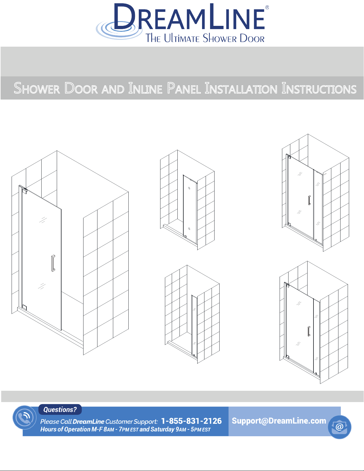
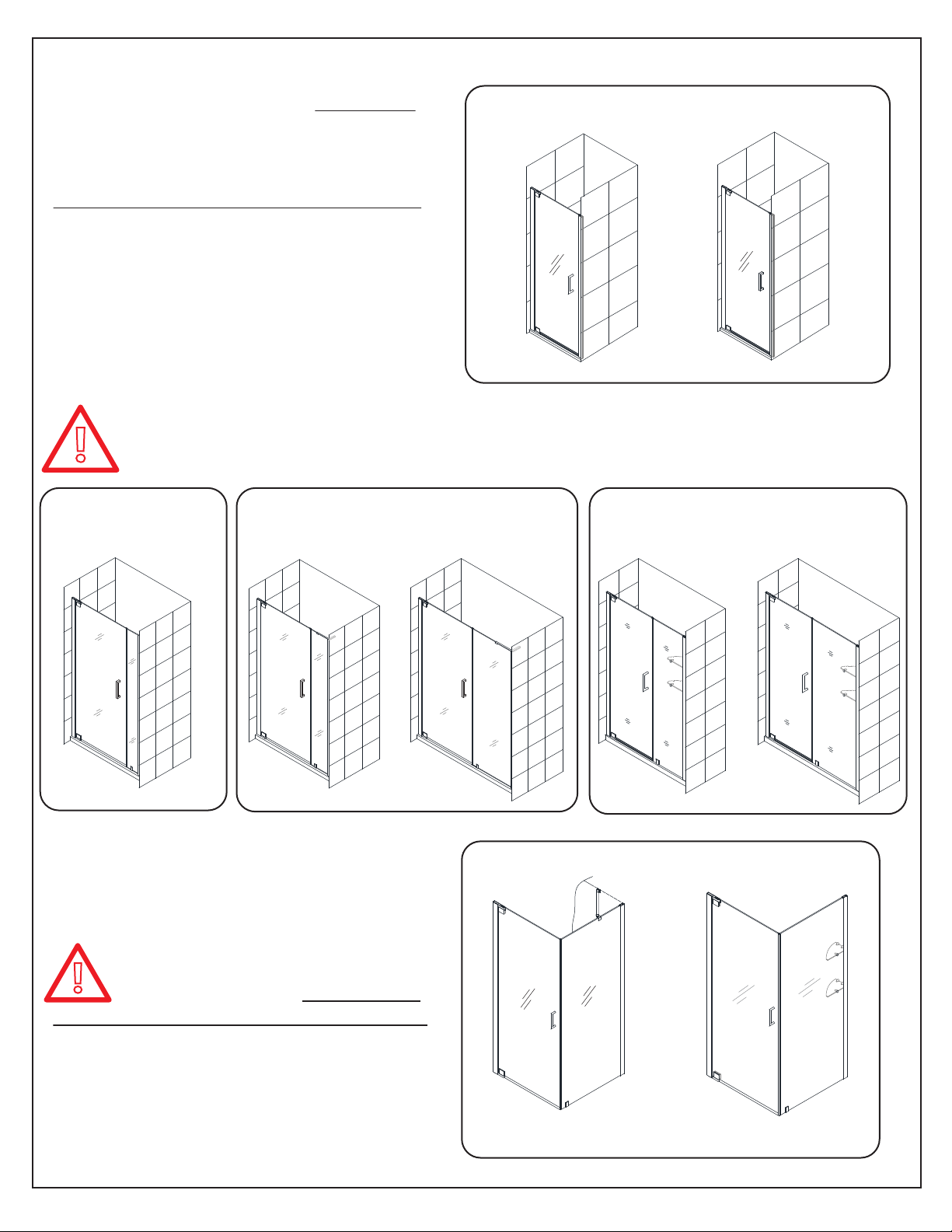
Elegance-LS / Atlas Shower Door Style B
SHOWER DOOR AND INLINE PANEL INSTALLATION INSTRUCTIONS
IMPORTANT
®
DreamLine
For the latest up-to-date technical drawings, manuals, warranty information or additional details please refer
to your model’s web page on DreamLine.com
reserves the right to alter, modify or redesign products at any time without prior notice.
Elegance-LS
Style B
=
with L-Bar™
+
+
STEP 1: Install Shower Door
For more information about DreamLine® Shower Doors, Tub Doors & Enclosures, please visit DreamLine.com
ELEGANCE-LS / ATLAS STYLE B
STEP 2: Install Shower Panel
Elegance-LS
Style B
=
with 6” panel
©2018 DreamLine. All Rights Reserved
Page 2
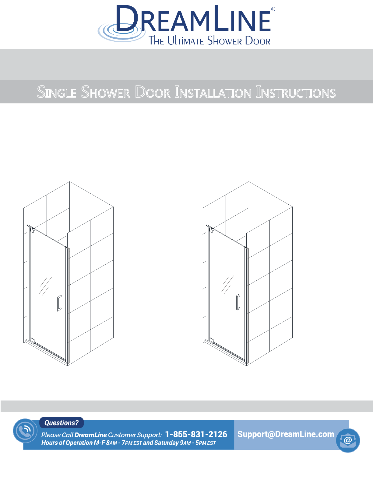
ELEGANCE / ELEGANCE-LS / ATLAS SINGLE DOOR
SINGLE SHOWER DOOR INSTALLATION INSTRUCTIONS
IMPORTANT
®
DreamLine
For the latest up-to-date technical drawings, manuals, warranty information or additional details please refer
to your model’s web page on DreamLine.com
reserves the right to alter, modify or redesign products at any time without prior notice.
Elegance Elegance-LS / Atlas
single sided handle
Model#s
SHDR-4125720-##
SHDR-4127720-##
SHDR-4128720-##
SHDR-4130720-##
SHDR-4132720-##
SHDR-4134720-##
SHDR-4135720-##
square back-to-back handle
Model#s
SHDR-4325000-##
SHDR-4327000-##
SHDR-4328000-##
SHDR-4330000-##
SHDR-4332000-##
SHDR-4334000-##
SHDR-4335000-##
Left-Swing installation shown
Please review this entire manual prior to installation.
For more information about DreamLine
ELEGANCE / ELEGANCE-LS / ATLAS (Style A) shower door manual Ver 1 01/2018
®
Shower Doors, Tub Doors & Enclosures, please visit DreamLine.com
##=finish code
01- Chrome
04- Brushed Nickel
06- Oil Rubbed Bronze
09- Satin Black
©2018 DreamLine. All Rights Reserved
Page 3
This model is treated with DreamLine’s
TM
exclusive ClearMax
Glass technology.
This is a specially formulated coating
that prevents the buildup of soap and
water spots.
Install the surface with the ClearMaxTM
label towards the inside of the shower.
Please note that depending on the
model, the glass may be coated on
either one or both surfaces.
For best results, squeegee the glass after
each use and dry with a soft cloth.
ELEGANCE / ELEGANCE-LS / ATLAS (Style A) shower door manual Ver 1 01/2018
©2018 DreamLine. All Rights Reserved
Page 4
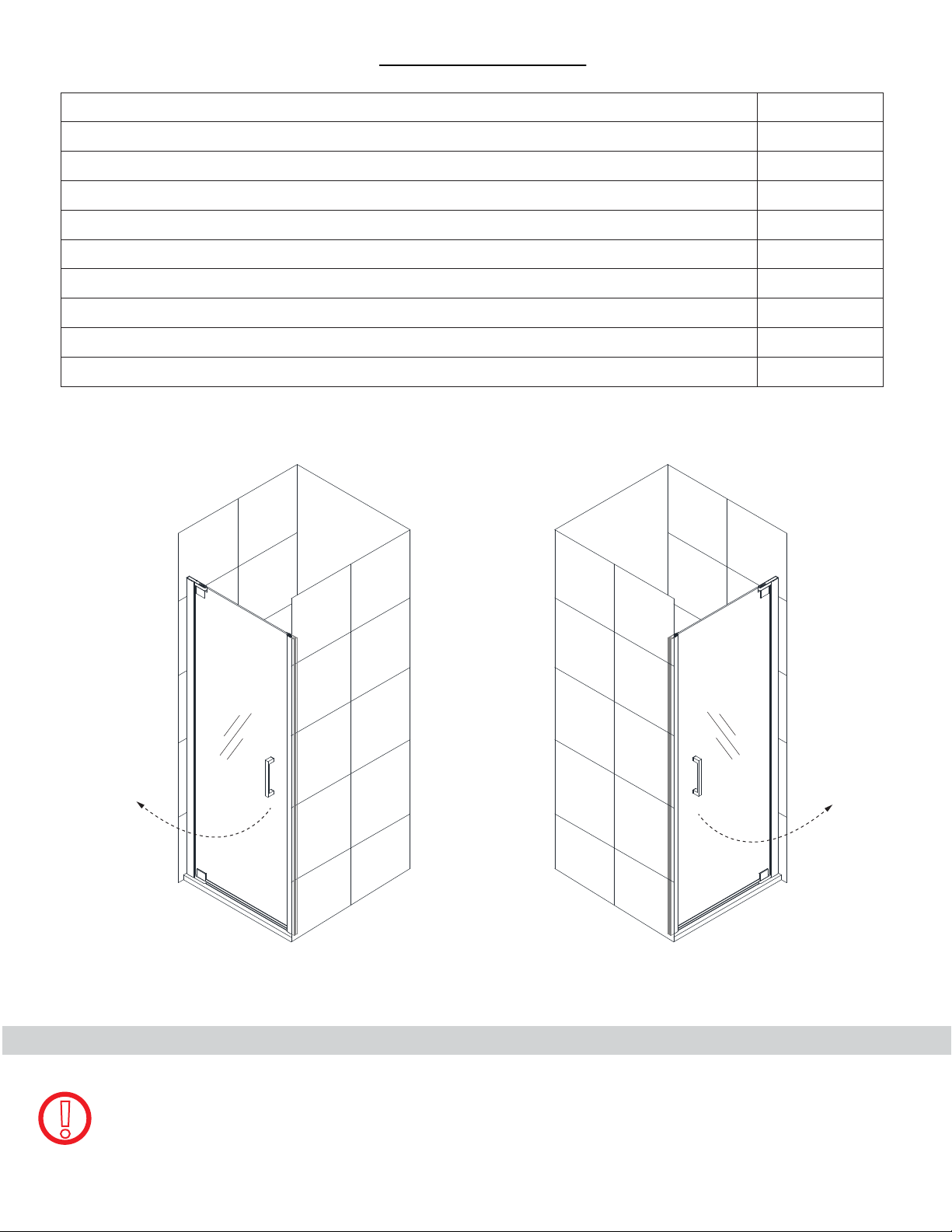
Table of Contents
Section title
Configurations
Preparation
Tools
Parts List
Adjustable Wall Profile System
Installation Steps
Pivot Assembly
Vinyl Seals
Product maintenance
Page #
2
3
4
5-6
7
8-18
9-10
13
19
Example: Elegance-LS / Atlas
Left-Swing door installation Right-Swing door installation
NOTE: This door is reversible for right or left-swing door installation.
The left-swing door installation is shown as an example throughout this manual.
!
For the right-swing door installation, simply begin on the opposite wall and reverse the
orientation of the steps shown.
ELEGANCE / ELEGANCE-LS / ATLAS (Style A) shower door manual Ver 1 01/2018
©2018 DreamLine. All Rights Reserved
Page 5
Configurations
This manual will describe the single door
installation of the Elegance or
Elegance-LS/Atlas models.
For models with additional panel glass,
use this manual first to install the door
and then use the manual that is packaged
with the panel glass to install the panel.
Additional Configurations with panel glass
!
Elegance-LS/Atlas
with 6” panel and
square back-to-back handle
For the installation of additional panel glass, use the panel glass installation manual
packaged with the panel glass (after the door is installed) for the following models:
Elegance-LS/Atlas
with L-Bar™ and
square back-to-back handle
Elegance
single sided handle
Style A
Elegance-LS/Atlas
square back-to-back handle
Style A
Elegance
with Support shelves and
single sided handle
Style BStyle BStyle B
Left-Swing door installation shown
For Elegance Enclosure models
!
Style D and Style E, reference the
sizing table in the enclosure panel manual
to install the door glass at the correct
dimension for the enclosure model size that
was purchased.
Style D
with support bar and
single sided handle
Left-Swing door with right side return panel installation shown
ELEGANCE / ELEGANCE-LS / ATLAS (Style A) shower door manual Ver 1 01/2018
Style C Style C
Elegance Enclosure
Style E
with support shelves and
single sided handle
©2018 DreamLine. All Rights Reserved
2
Page 6
Preparation
1. Prior to installation, examine all boxes and packages for shipping damage and compare the piece
count with the packing slip. After opening all boxes and packages read this introduction carefully.
Check that all of the necessary parts are included in the package by checking off the components on
the “Detailed Diagram of Shower Door Components”. If the unit has been damaged, has a finishing
defect, or has missing parts, please contact our customer support department within 3 business days
of the delivery date. Please note that DreamLine® will not replace any damaged products or
missing parts free of charge after 3 business days or if the product has been installed. Contact
®
DreamLine
of purchase to help identify the original order.
2. Please note that you should consult your local building codes with questions on installation
compliance standards. Building and plumbing codes may vary by location, and DreamLine
not responsible for code compliance standards for your project and will not accept any returns.
3. If this unit is going to be installed in a new construction, please install all of the required plumbing
and drainage before installing the shower. Use a competent and licensed (if required by local code)
plumber for all plumbing installation
4. Make sure that prior to beginning the installation, the surfaces are leveled and solid and will be able
to support the total weight of the unit. Also make sure the walls are at right angles. Irregular
installation surface level, radius corners or improper angle of side walls will result in serious problems
for your installation. Note that some adjustments and drilling will be necessary during the installation
process.
if you have any questions, and please provide an order number, job name or other proof
®
is
5. Protect all primary surfaces of the product during installation. Never set the glass down directly onto
a tile floor. Leave corner protectors in place until necessary to remove them. Always use a piece of
wood or cardboard to protect the bottom edge and corners of the glass prior to and during
installation.
6. This unit must be installed upon a finished threshold and against finished walls.
7. This model has 1” of adjustment per wall profile for out-of-plumb wall conditions and overall
width within the model size.
8. Professional installation recommended.
NOTE: DO NOT attach the handle to the door glass until instructed.
DO NOT use the handle to lift the glass during installation. This may result in damage to the
!
glass and/or serious injury. Always use an assistant or a professional grade glass suction cup
when handling heavy glass.
ELEGANCE / ELEGANCE-LS / ATLAS (Style A) shower door manual Ver 1 01/2018
©2018 DreamLine. All Rights Reserved
3
Page 7
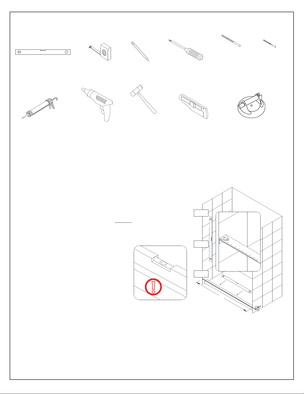
Tools
Level
Silicone
Tape
Measure
Power
Drill
Pencil
Soft Head
Hammer
Phillips
Screwdriver
Razor Knife
Drill bit
Ø5/16"
(8mm)
Professional grade
Glass suction cup
Drill bit
Ø1/8"
(3mm)
Top
Tip: Measure the finished opening before
proceeding with the installation to be sure
that the correct model size has been
ordered.
Threshold must be level.
Middle
Tip: Prior to installation, cover the
shower/tub drain with tape to prevent
losing screws or small parts.
Tip: Set screw gun clutch to low setting
when installing screws and bolts to
prevent stripping the heads.
NOTE: Unpack your unit carefully and inspect it. Lay it out and identify all parts using the detailed
diagram and packing list in this manual as a reference. Before discarding the carton, check for small
hardware bags that may have fallen to the bottom of the box. If any parts are damaged or missing,
®
please contact DreamLine
your model configuration.
for replacement. The shipping boxes may contain extra parts not used in
!
Bottom
W
NOTE: Retain these installation instructions for future reference.
ELEGANCE / ELEGANCE-LS / ATLAS (Style A) shower door manual Ver 1 01/2018
©2018 DreamLine. All Rights Reserved
4
Page 8
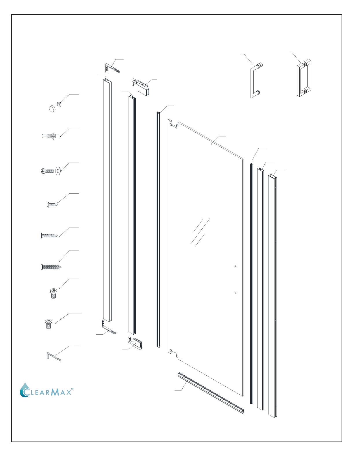
Detailed Diagram of shower door components
09
12
13
14
01
08
02
07
top left or bottom right pivot
(x70-11/16”)
10
top
06
Handle for
Elegance model
03
10
06-LS
Handle for
Elegance-LS / Atlas
model
(x72”)
04
05
15
16
17
18
19
08
07
bottom left or top right pivot
bottom
11
The glass surface
with the ClearMax™
label must be
installed to face
inside of the shower
ELEGANCE / ELEGANCE-LS / ATLAS (Style A) shower door manual Ver 1 01/2018
©2018 DreamLine. All Rights Reserved
5
Page 9
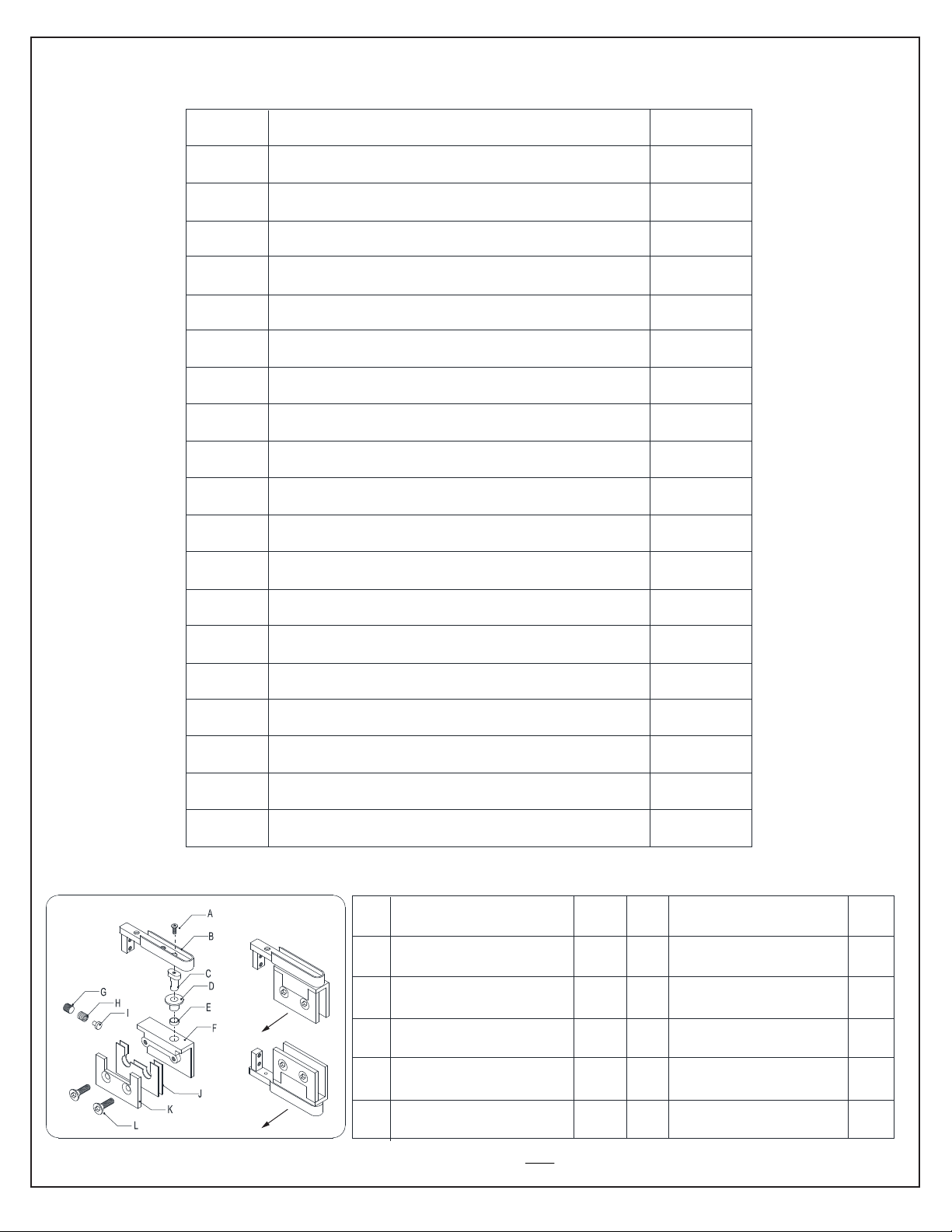
Parts List
PART#
01
02
03
04
05
06 / 06-LS
07
08
09
10
11
12
DESCRIPTION
Wall profile for
Glass profile for
Pivot
Pivot
side
side
Door glass
Glass profile
Wall profile
Handle (Elegance / Elegance-LS)
Pivot assembly (top and bottom)
Pivot retainer
Decorative cover with washer
ap-in Anti-water strip (1 long / 1 short)
* Sn
Sweep Vinyl seal
Wall anchor
QTY
1pc
1pc
1pc
1pc
1pc
1set
1pair
2pcs
8pcs
2pcs
1pc
12pcs
*(see note in step #10)
13
14
15
16
17
18
19
Pivot assembly (part#07) -
inside
Bolt M4x16 (with washer)
Pan head screw ST4.2x10
Flat head screw ST4.2x25
Large Truss head screw ST4.2x40
Round head socket bolt M6x12
Flat head socket bolt M6x12
Hex wrench
parts per assembly
Flat head bolt M4x8
A
Pivot bracket
B
Pivot axis
C
Washer A
D
(1 top and 1 bottom)
1pc
1pc
1pc
1pc
G
Bolt M12x10
Spring
H
Core
I
J
Clear Gasket
4pcs
8pcs
2pcs
13pcs
1pc
1pc
2pcs
1pc
1pc
1pc
1set
E
Washer B
inside
Pivot body
F
The above pivot assembly parts list is for identification only. It is not necessary to completely disassemble the hinge.
ELEGANCE / ELEGANCE-LS / ATLAS (Style A) shower door manual Ver 1 01/2018
1pc
1pc
K
L
Back plate
Bolt
1pc
2pcs
©2018 DreamLine. All Rights Reserved
6
Page 10

Adjustable Wall Profile System
Glass Profile
1
”
m
a
x
Wall Profile
!
screw
decorative cap
The Glass Profiles can be adjusted
within the Wall Profiles for overall
width or to correct for out-of-plumb
conditions within the model size.
Screw them together after making
final adjustments.
1 32
Ø1/8"
washer
inside
ELEGANCE / ELEGANCE-LS / ATLAS (Style A) shower door manual Ver 1 01/2018
©2018 DreamLine. All Rights Reserved
7
Page 11
!
!
Installation steps
The Elegance-LS / Atlas Left-Swing
door installation is shown as an
example throughout this manual.
1
NOTE: If this door is to be part of an
enclosure model, refer to the model size
table in the enclosure panel glass manual
for the correct placement of the door glass
to match the enclosure size.
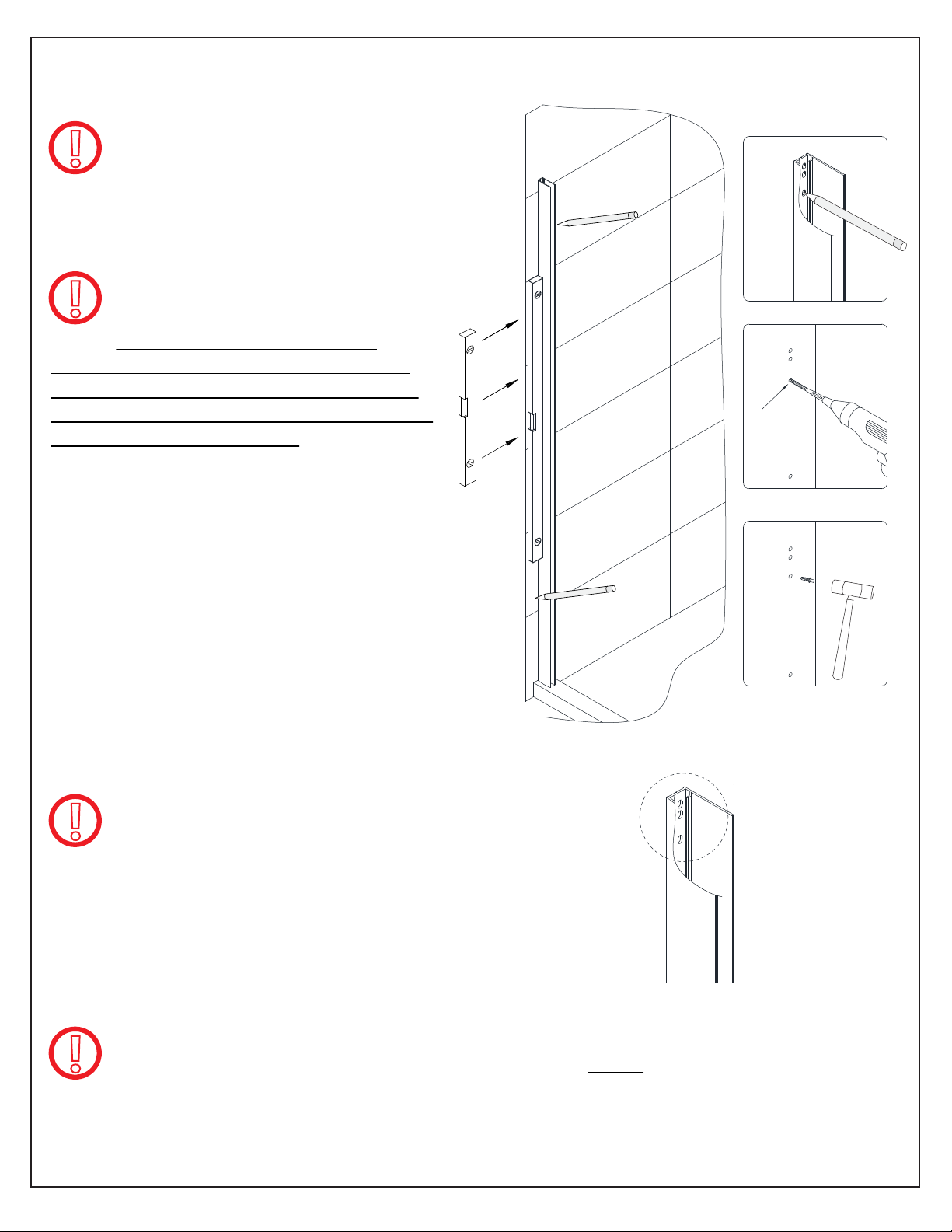
1. Position the Wall Profile for Pivot Side (#01)
onto the threshold and against the desired
hinge-side wall and adjust to plumb.
Mark all eight (8) drill holes on the wall through
the predrilled holes in the Wall Profile for Pivot
Side (#01).
Next, drill the holes using a Ø5/16” drill bit and
insert the Wall Anchors (#12). (Fig 1)
2**
Ø5/16”
3**
Fig 1
NOTE: The Wall Profile for Pivot Side (#01) has an
!
!
ELEGANCE / ELEGANCE-LS / ATLAS (Style A) shower door manual Ver 1 01/2018
additional pair of holes at each end and is milled out
to accept the Pivot Retainers (#08) (Fig 1.1). These
extra holes are not present in the Wall Profile (#05)
that is used for the strike side (or panel side for
models with an additional panel).
**When installing into a stud (recommended but not required) drill Ø1/4” holes up
to the stud and drill Ø1/8” pilot holes into the stud and do not use the wall anchors.
©2018 DreamLine. All Rights Reserved
8
Page 12
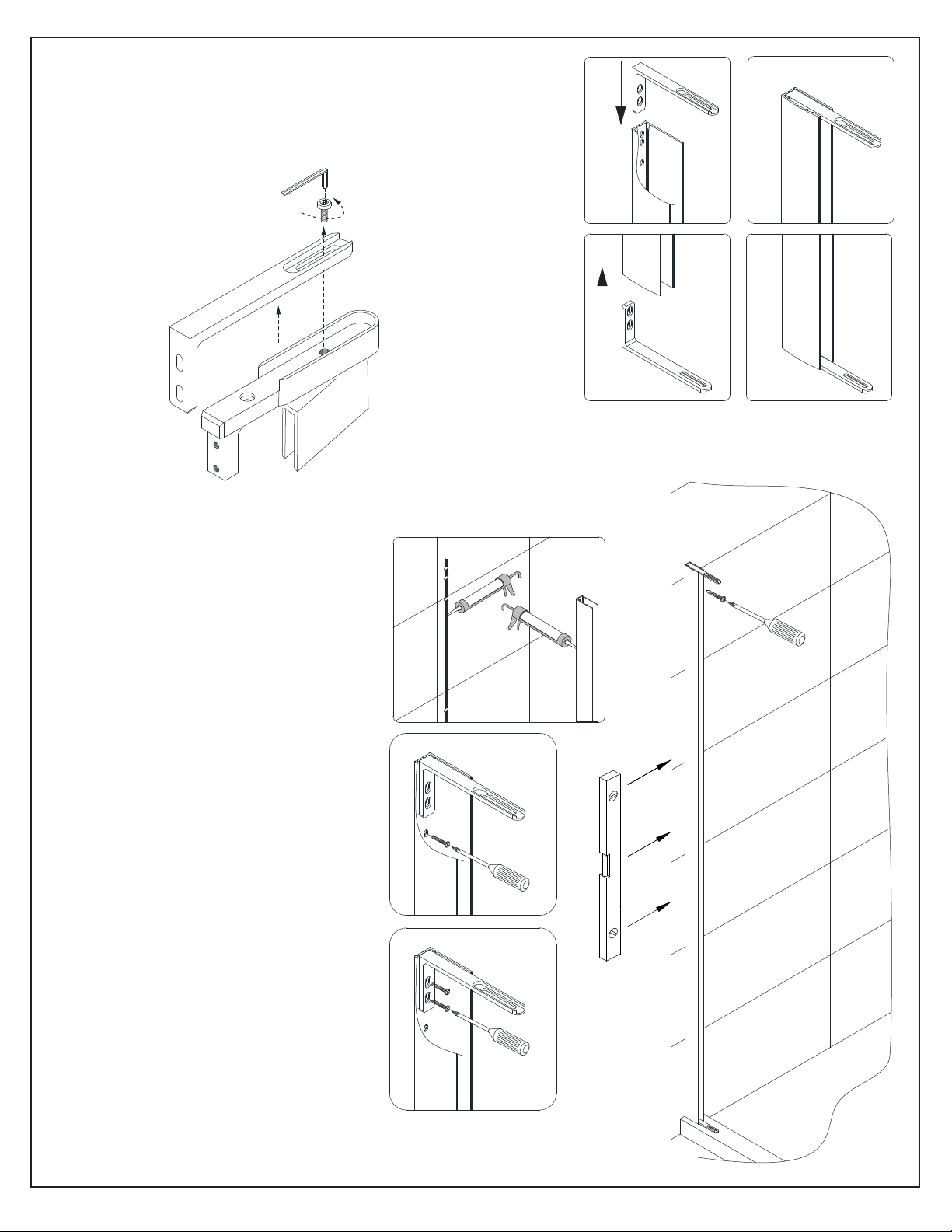
2. Separate the Pivot Retainers (#08) from the Pivot
Assemblies (#07) by removing the Round Head Socket Bolt
M6×12 (#17).
of the Wall Profile for Pivot Side (#01). (Fig 2)
Insert the Pivot Retainers (#08) into both ends
1
2
top left/ bottom right pivot shown
as viewed from outside
3. Run a bead of silicone along the
holes on the wall and on the back of
the Wall Profile for Pivot Side (#01).
Attach the Wall Profile for Pivot
Side (#01) and Pivot Retainer (#08)
to the wall using the Large Truss Head
Screws ST4.2×40 (#16). (Fig 3)
1
3
4
Fig 2
2
3
Fig 3
ELEGANCE / ELEGANCE-LS / ATLAS (Style A) shower door manual Ver 1 01/2018
©2018 DreamLine. All Rights Reserved
9
Page 13
NOTE: The Glass Profile for Pivot Side (#02)
!
is shorter and has an additional pair of holes
at each end for the Pivot Assembly (#07). These extra
holes are not present in the Glass Profile (#04) that is
used for the strike side/panel side.
4. Attach the Pivot Assemblies (#07) to the top and
the bottom ends of the Glass Profile for Pivot Side
(#02) with the Flat Head Screws ST4.2×25 (#15)
and M4×16 bolts and washers (#13). (Fig 4)
NOTE: Attach the hinges to the Glass Profile for
Pivot Side (#02) as shown in Fig 4.
!
The Back Plate (K) of the Pivot Assembly (#07)
must face inside of the shower.
(see the diagram parts list for hinge part details)
1
outside
outside
2
outside
3
Back Plate (K)
outside
Inside of
shower
Fig 4
The two piece wall profile system (consisting of the glass profiles and wall profiles)
!
will allow for overall width and/or out-of-plumb adjustment within the model size.
5. Slide the Glass Profile for Pivot Side (#02) with the attached Pivot Assemblies (#07) into the Wall
Profile for Pivot Side (#01) and secure the top Pivot Retainer (#08) to the top Pivot Assembly (#07)
with the Round Head Socket Bolt M6×12 (#17). (Fig 5)
1 2 3
outside
Fig 5
ELEGANCE / ELEGANCE-LS / ATLAS (Style A) shower door manual Ver 1 01/2018
Fully tighten this bolt after all
adjustments with the glass profile
have been made
©2018 DreamLine. All Rights Reserved
10
Page 14
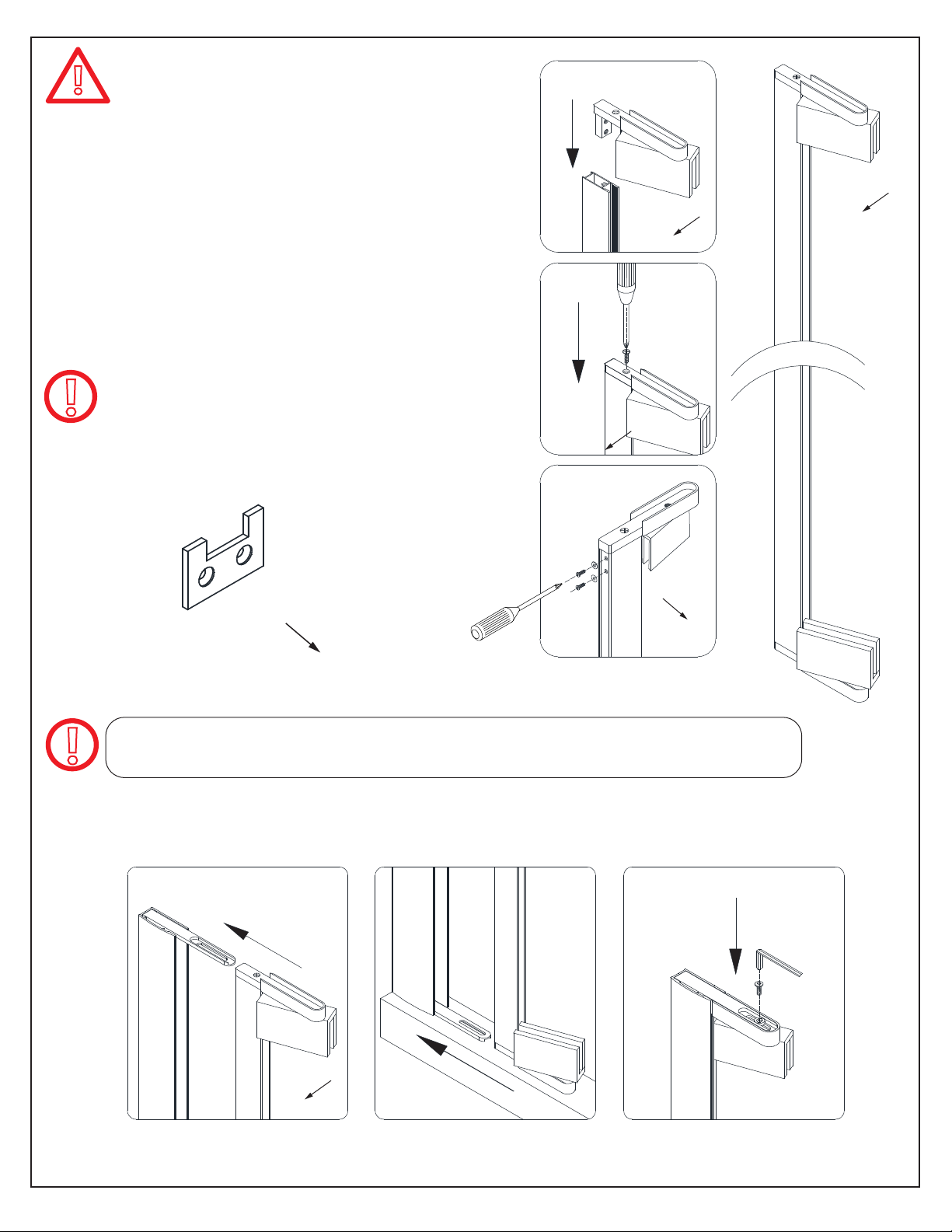
NOTICE: The Door Glass (#03) has a top and a bottom notch for the pivots. The notch at
!
See Pivot Assembly parts list on Page 6 for reference
the top is deeper and the notch at the bottom is shallower (to allow space for the bottom
sweep vinyl). Identify this difference to prevent installing the Door Glass upside-down.
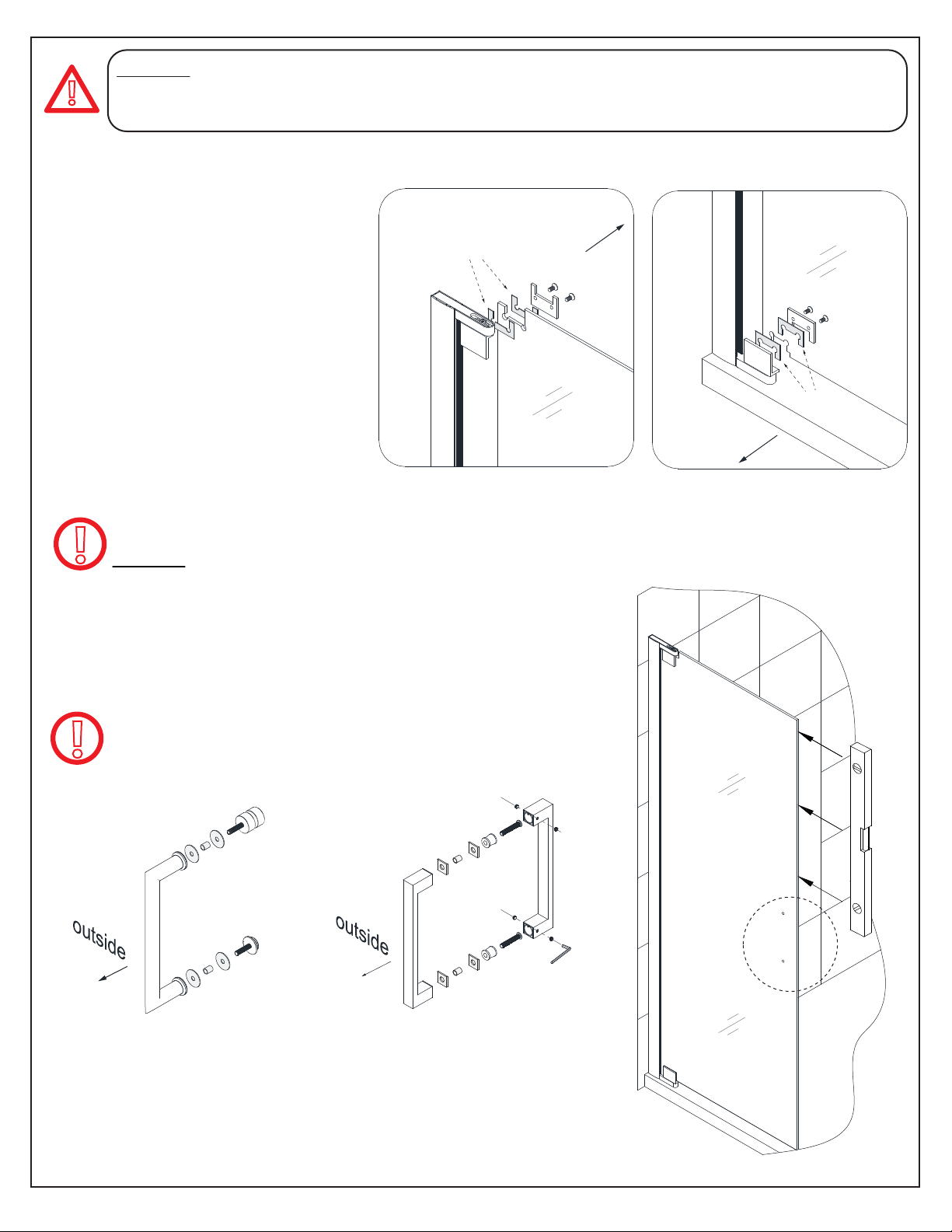
6. Remove the Bolts (L) and Back
Plates (K) from the top and bottom
Pivot Assemblies (#07).
Position the Door Glass (#03) onto
the Pivot Assemblies (#07). Hold
the Clear Gaskets (J) in place on
either side of the Door Glass
and attach the Back Plates (K).
Tightly secure the Door Glass (#03) to
the Pivot Assemblies (#07) using
Bolts (L). (Fig 6)
Use caution when handling the Door Glass.
!
DO NOT lift the Door Glass with the handle.
1
inside
gaskets
top
7. Attach the *Handle (#06 or #06-LS) onto the Door Glass (#03).
(Fig 7)
2
bottom
gaskets
outside
Fig 6
!
*The Elegance model
comes with the single
sided handle.
Elegance
*The Elegance-LS / Atlas
model comes with the
square back-to-back handle.
Elegance-LS / Atlas
Fig 7
ELEGANCE / ELEGANCE-LS / ATLAS (Style A) shower door manual Ver 1 01/2018
©2018 DreamLine. All Rights Reserved
11
Page 15

8. Open the Door Glass (#03) to expose the bottom Pivot Retainer (#08). (Fig 8)
Fig 8
NOTE: Sealing the hole in the bottom Pivot Retainer is important.
!
9. Seal the unused hole in the bottom Pivot Assembly (#07) with the Flat Head Socket Bolt M6×12
(#18) OR attach the Pivot Retainer (#08) to the Shower base or threshold by drilling an Ø1/8” hole and
using a Large Truss Head Screw ST4.2×40 (#16).
Apply silicone sealant over the Screw (#16) or Bolt (#18) to prevent leakage for either method. (Fig 9)
!
Screwing the bottom Pivot Retainer to the threshold is optional.
*Any width and/or out-of-plumb adjustments using the adjustable wall profile system
must be made prior to screwing the Pivot Assembly (#07) down into the threshold.
1 2*
OR
3
Fig 9
When installing the door along with an inline panel or enclosure model, postpone
!
ELEGANCE / ELEGANCE-LS / ATLAS (Style A) shower door manual Ver 1 01/2018
this step until after alignment with the panel glass.
©2018 DreamLine. All Rights Reserved
12
Page 16

10. Firmly push the shorter Snap-In Anti-Water Strip (#10) into the vertical groove of the Glass
Profile for Door Glass (#02). (Fig 10)
1
hinge side
door
outside
2
inside
door
outside outside
3
door
Fig 10
!
NOTE:
◾ When installing the single door model, use both of the Snap-In Anti-Water Strips (#10) (Fig 10
& Fig 11) included with the Door Glass that snap into the Glass Profiles, (snap the shorter one into
the hinge side glass profile and the longer one into the strike side glass profile).
◾ When installing a door with an inline panel or an enclosure panel, discard the longer (x72”)
Snap-In Anti-Water Strip (#10) and attach the Anti-Water Strip (inline) or Anti-Water Strip
(enclosure) (that is packaged with the panel glass) onto the edge of the Panel Glass as instructed in
the panel installation manual.
For the single door installation, continue on to step #11.
!
ELEGANCE / ELEGANCE-LS / ATLAS (Style A) shower door manual Ver 1 01/2018
If installing a model that includes panel glass (inline or enclosure), complete
the installation steps using the manual that is packaged with the panel glass.
Elegance w/inline panel
Style B Style C Style CStyle B Style D
with L-Bar™with 6” inline panel
with Support Shelves with Support Shelveswith Support Bar
Elegance EnclosureElegance-LS / Atlas w/inline panel
Style E
©2018 DreamLine. All Rights Reserved
13
Page 17

11. Push the Glass Profile (#04) into the Wall Profile (#05) and snap the longer Anti-Water Strip (#10)
into the Glass Profile (#04). (Fig 11)
1
2
Fig 11
ELEGANCE / ELEGANCE-LS / ATLAS (Style A) shower door manual Ver 1 01/2018
©2018 DreamLine. All Rights Reserved
14
Page 18

12. Hold the Door Glass (#03) in the closed position, parallel to the threshold.
Adjust the Glass Profile (#04) within the Wall Profile (#05) and adjust the position of the Wall Profile
(#05) on the wall to ensure that the Door Glass (#03) makes tight contact with the flange of the
Anti-Water Strip (#10) from top to bottom. Use a level to ensure that the Door Glass (#03) and the
Wall Profile (#05) are plumb, but make sure that the door glass makes full contact with the strike vinyl.
Draw a line on the wall along the vertical edge of the Wall Profile (#05). Detach the Wall Profile (#05)
from the Glass Profile (#04). Place the Wall Profile (#05) back onto the outlined position on the wall
and mark the holes for drilling through the pre-drilled holes in the Wall Profile (#05).
Drill the holes in the wall using a Ø5/16” drill bit. Insert the Wall Anchors (#12) into the holes. (Fig 12)
Adjust the glass profile
within the wall profile
Door
5
1
3
2
1
/
1
6
”
-
1
/
8
”
4
6
Make sure that the reveal is even along the threshold.
ELEGANCE / ELEGANCE-LS / ATLAS (Style A) shower door manual Ver 1 01/2018
Ø5/16”
Fig 12
©2018 DreamLine. All Rights Reserved
15
Page 19

13. Apply silicone to the back of the Wall Profile (#05) and around the holes in the wall.
Install the Wall Profile (#05) to the wall using the Large Truss Head Screws ST4.2×40 (#16).
Slide the Glass Profile (#04) back into the Wall Profile (#05). (Fig 13)
1
2
3
Fig 13
ELEGANCE / ELEGANCE-LS / ATLAS (Style A) shower door manual Ver 1 01/2018
©2018 DreamLine. All Rights Reserved
16
Page 20

14. Adjust the overall width of the Door using the Glass Profiles (#02 and #04) on one or both sides of
the opening. Slide the Glass Profiles out of the Wall Profiles up to 1” per side as necessary to maintain a
1/16" - 1/8" reveal between the Door Glass (#03) and the Anti-Water Strip (#10).
Hold the top of the Door Glass (#03) level and tighten the pivot assembly in place with the Round Head
Socket Bolt M6×12 (#17) (Fig 14.3). Test the operation of the door before proceeding to the next step.
(Fig 14)
Use caution not to damage the edges of the door glass during adjustments
!
(Fig 14.2)
1
Door
Fig 14
15. After final adjustments and leveling of the assembled door and profiles, drill holes into the Glass
Profiles (#02 and #04) through the pre-drilled holes in both Wall Profiles (#01 and #05) using an
Ø1/8” drill bit. (Fig 15)
NOTE: Only drill through the first layer of the Glass Profile.
!
Use the Pan Head Screws ST4.2×10 (#14) and Decorative Cover Washers (#09) to secure the Glass
Profiles (#02 and #04) inside of the Wall Profiles (#01 and #05). Cover the exposed screws with the
Decorative Covers (#09).
2
3
1
inside
4
inside
ELEGANCE / ELEGANCE-LS / ATLAS (Style A) shower door manual Ver 1 01/2018
2
5
Fig 15
3
6
If necessary, return to
Step# 9 to screw the
!
bottom pivot retainer
to the threshold.
Otherwise, continue
on to the next step.
©2018 DreamLine. All Rights Reserved
17
Page 21

16. Cut the Sweep Vinyl Seal (#11) to the width of the Door Glass (#03). Next, trim the Sweep Vinyl
Seal (#11) to size up to the bottom pivot. Close the door and notch off the deflector on the inner side
of the Sweep Vinyl Seal (#11) where it overlaps the strike vinyl when the door is closed (Fig 16.3).
Press the Sweep Vinyl Seal (#11) tightly onto the bottom edge of the Door Glass (#03). (Fig 16)
1
2
3
3/8” (+/-)
Fig 16
17. Apply a good quality mildew-resistant silicone along the Wall Profiles where they attach to the
wall and along the threshold and the bottom Pivot Bracket. (Fig 17)
24
Hours
24
Hours
54
Fig 17
Allow 24 hours for the silicone to cure before using the shower.
!
ELEGANCE / ELEGANCE-LS / ATLAS (Style A) shower door manual Ver 1 01/2018
©2018 DreamLine. All Rights Reserved
18
Page 22

Product Maintenance
BASES and BACKWALLS: To ensure long-lasting life for your acrylic back walls, wipe them off after
each use with a soft cloth. To clean the acrylic back walls use non-abrasive sprays or cream based
cleaners. Avoid the use of aerosol spray cleaners. Never use abrasive cleansers, metal brushes or
scrapers that could scratch or dull the surface.
GLASS: To ensure long-lasting life for your glass shower products, wipe them off after each use with
a soft cloth. Rinse and wipe off the glass using either a soft cloth or a squeegee to prevent soap
buildup and water spots (Hard water can etch the surface of the glass over time if left to dry). To
prevent scratching the surface: never use abrasive cleaners or cleaning products that contain
scouring agents. Never use bristle brushes or abrasive sponges that may scratch the surface.
HARDWARE: To ensure a long-lasting finish, wipe off the metal parts after each use with a soft cloth.
Do not use abrasive cleaners or cleaning products containing ammonia, bleach or acid. If accidentally
used, rinse the surface as soon as possible to prevent damage to the finish (peeling or corrosion).
After cleaning the polished finishes, rinse thoroughly and wipe dry with a soft cloth.
Clean stainless steel surfaces at least once a week. When applying stainless steel cleaner or polish to
stainless steel hardware, work with (not across) the grain. Never use an abrasive sponge or cloth,
steel wool or wired brush as these may permanently scratch the surfaces.
NOTE: To maximize the life of your door, it is important to regularly inspect the
glass and all hardware for misalignment, proper attachment, and/or damage.
Contact DreamLine
®
DreamLine
shower doors and enclosures are designed not to leak when installed
®
with any questions or concerns.
properly and the flow of water is not pointed directly at the hinges or vinyl seals.
ELEGANCE / ELEGANCE-LS / ATLAS (Style A) shower door manual Ver 1 01/2018
19
Page 23

For more information on DreamLine
TEL: 866-731-2244
FAX: 866-857-3638
DREAMLINE.COM
®
Shower Doors and Enclosures please visit DreamLine.com
©2018 DreamLine. All Rights Reserved
Page 24

© DreamLine
All Rights Reserved
© DreamLine
All Rights Reserved
Install the
door first
INLINE PANEL - STYLE B
INLINE PANEL INSTALLATION INSTRUCTIONS
IMPORTANT
®
DreamLine
For the latest up-to-date technical drawings, manuals, warranty information or additional details please refer
to your model’s web page on DreamLine.com
reserves the right to alter, modify or redesign products at any time without prior notice.
This inline panel is used with the following models:
6” inline panel
inline panel
w/Support Bar
(for Unidoor)
inline panel
w/L-Bar™
Right-side inline panel installation shown
PLEASE REVIEW THIS ENTIRE MANUAL PRIOR TO INSTALLATION
UNIDOOR Style B
w/6” panel
ELEGANCE-LS / ATLAS
Style B w/6” panel
UNIDOOR Style B
w/Support Bar
ELEGANCE-LS /ATLAS
Style B w/L-Bar™
UNIDOOR -LS Style B
w/L-Bar™
For more information about DreamLine
INLINE PANEL - Style B shower panel manual Ver 1 Rev 1 07/2018
®
Shower Doors, Tub Doors & Enclosures, please visit DreamLine.com
©2018 DreamLine. All Rights Reserved
Page 25

© DreamLine
All Rights Reserved
© DreamLine
All Rights Reserved
Model #s
UNIDOOR - Style B
w/ 6” inline
MODEL #s
SHDR-20297210-##
SHDR-20307210-##
SHDR-20317210-##
SHDR-20327210-##
SHDR-20337210-##
SHDR-20347210-##
SHDR-20357210-##
SHDR-20367210-##
UNIDOOR - Style B
inline w/ Support Bar
MODEL #s
SHDR-20417210C-##
SHDR-20427210C-##
SHDR-20437210-##
SHDR-20447210-##
SHDR-20457210-##
SHDR-20467210-##
SHDR-20477210-##
SHDR-20487210-##
SHDR-20477210C-##
SHDR-20487210C-##
SHDR-20497210-##
SHDR-20507210-##
SHDR-20517210-##
SHDR-20527210-##
SHDR-20537210-##
SHDR-20547210-##
SHDR-20537210C-##
SHDR-20547210C-##
SHDR-20557210-##
SHDR-20567210-##
SHDR-20577210-##
SHDR-20587210-##
SHDR-20597210-##
SHDR-20607210-##
UNIDOOR - Style B
inline w/L-Bar™
MODEL #s
SHDR-2035723-##
SHDR-2036723-##
SHDR-2037722-##
SHDR-2038722-##
SHDR-2039722-##
SHDR-2040722-##
SHDR-2041722-##
SHDR-2042722-##
SHDR-2041723-##
SHDR-2042723-##
SHDR-2043722-##
SHDR-2044722-##
SHDR-2045722-##
SHDR-2046722-##
SHDR-2047722-##
SHDR-2048722-##
SHDR-2047723-##
SHDR-2048723-##
SHDR-2049722-##
SHDR-2050722-##
SHDR-2051722-##
SHDR-2052722-##
SHDR-2053722-##
SHDR-2054722-##
SHDR-2053723-##
SHDR-2054723-##
SHDR-2055722-##
SHDR-2056722-##
SHDR-2057722-##
SHDR-2058722-##
SHDR-2059722-##
SHDR-2060722-##
ELEGANCE-LS / ATLAS
- Style B
w/ 6” inline
MODEL #s
SHDR-4325060-##
SHDR-4327060-##
SHDR-4328060-##
SHDR-4330060-##
SHDR-4332060-##
SHDR-4334060-##
SHDR-4335060-##
ELEGANCE-LS / ATLAS
- Style B
inline w/L-Bar™
MODEL #s
SHDR-4325120-##
SHDR-4327120-##
SHDR-4328120-##
SHDR-4330120-##
SHDR-4332120-##
SHDR-4334120-##
SHDR-4335120-##
SHDR-4325180-##
SHDR-4327180-##
SHDR-4328180-##
SHDR-4330180-##
SHDR-4332180-##
SHDR-4334180-##
SHDR-4335180-##
SHDR-4325240-##
SHDR-4327240-##
SHDR-4328240-##
SHDR-4330240-##
SHDR-4332240-##
SHDR-4334240-##
SHDR-4335240-##
SHDR-4325300-##
SHDR-4327300-##
SHDR-4328300-##
SHDR-4330300-##
SHDR-4332300-##
SHDR-4334300-##
SHDR-4335300-##
## = Finish
INLINE PANEL - Style B shower panel manual Ver 1 Rev 1 07/2018
01- Chrome
04- Brushed Nickel
06- Oil Rubbed Bronze
09- Satin Black
©2018 DreamLine. All Rights Reserved
Page 26

© DreamLine
All Rights Reserved
© DreamLine
All Rights Reserved
This model is treated with DreamLine’s
TM
exclusive ClearMax
This is a specially formulated coating
that prevents the buildup of soap and
water spots.
Install the surface with the ClearMaxTM
label towards the inside of the shower.
Please note that depending on the
model, the glass may be coated on
either one or both surfaces.
For best results, squeegee the glass after
each use and dry with a soft cloth.
Glass technology.
INLINE PANEL - Style B shower panel manual Ver 1 Rev 1 07/2018
©2018 DreamLine. All Rights Reserved
Page 27

© DreamLine
All Rights Reserved
© DreamLine
All Rights Reserved
Table of Contents
Section title
Preparation
Tools
Detailed Diagram of Shower Panel Components
Parts List
Adjustable Wall Profile System
Installation Steps
Vinyl Seals
Support Bar Installation
L-Bar Assembly
Product maintenance
Page #
2
3
4
5
6
7-16
9
13
14
17
NOTE: This model is reversible for right or left-side panel installation.
INLINE PANEL - Style B shower panel manual Ver 1 Rev 1 07/2018
The right-side panel installation is shown as an example throughout this manual.
!
For the left-side panel installation, simply begin on the opposite wall and reverse the
orientation of the steps shown.
Right-side inline panel installation Left-side inline panel installation
©2018 DreamLine. All Rights Reserved
Page 28

© DreamLine
All Rights Reserved
© DreamLine
All Rights Reserved
Preparation
1. Prior to installation, examine all boxes and packages for shipping damage and compare the piece
count with the packing slip. After opening all boxes and packages read this introduction carefully.
Check that all of the necessary parts are included in the package by checking off the components on
the “Detailed Diagram of Shower Panel Components”. If the unit has been damaged, has a finishing
defect, or has missing parts, please contact our customer support department within 3 business
days of the delivery date. Please note that DreamLine® will not replace any damaged products
or missing parts free of charge after 3 business days or if the product has been installed.
®
Contact DreamLine
other proof of purchase to help identify the original order.
2. Please note that you should consult your local building codes with questions on installation
compliance standards. Building and plumbing codes may vary by location, and DreamLine
not responsible for code compliance standards for your project and will not accept any
returns.
3. If this unit is going to be installed in a new construction, please install all of the required plumbing
and drainage before installing the shower. Use a competent and licensed (if required by local code)
plumber for all plumbing installation
if you have any questions, and please provide an order number, job name or
®
is
4. Make sure that prior to beginning the installation, the surfaces are leveled and solid and will be
able to support the total weight of the unit. Also make sure the walls are at right angles. Irregular
installation surface level, radius corners or improper angle of side walls will result in serious
problems for your installation. Note that some adjustments and drilling will be necessary during the
installation process.
5. Protect all primary surfaces of the product during installation. Never set the glass down directly
onto a tile floor. Leave corner protectors in place until necessary to remove them. Always use a piece
of wood or cardboard to protect the bottom edge and corners of the glass prior to and during
installation.
6. This unit must be installed upon a finished threshold and against finished walls.
7. This model requires that you drill into the threshold for proper installation.
manufacturer of the base or threshold material with any questions regarding the drilling of holes into
their product.
8. This model requires a minumum of 1-1/2” of flat level threshold space for installation.
9. Professional installation recommended.
Contact the
NOTE: DO NOT attach the handle to the door glass until instructed.
INLINE PANEL - Style B shower panel manual Ver 1 Rev 1 07/2018
!
DO NOT use the handle or towel bar to lift the glass during installation. This may result in damage
to the glass and/or serious injury. Always use an assistant or a professional grade glass suction cup
when handling heavy glass.
©2018 DreamLine. All Rights Reserved
2
Page 29

© DreamLine
All Rights Reserved
© DreamLine
All Rights Reserved
Tools
Power
Drill
Knife
Tape
MeasureLevel
Phillips
Screwdriver
Professional-grade
Glass suction cup
Pencil
Silicone
Top
Drill bit
(Ø5/16")
(8mm)
Soft Head
Hammer
Drill bit
(Ø1/8")
(3mm)
Mallet
Tip: Measure the finished opening before
proceeding with the installation to be sure that
the correct model size has been ordered.
Threshold must be level
Middle
Tip: Prior to installation, cover the
shower/tub drain with tape to
prevent losing screws or small parts.
Tip: Set screw gun clutch to low
setting when installing screws and
bolts to prevent stripping the heads.
NOTE: Unpack your unit carefully and inspect it. Lay it out and identify all parts using the detailed
diagram and packing list in this manual as a reference. Before discarding the carton, check for small
hardware bags that may have fallen to the bottom of the box. If any parts are damaged or missing,
please contact DreamLine
your model configuration.
®
for replacement. The shipping boxes may contain extra parts not used in
!
Bottom
W
NOTE: Retain these installation instructions for future reference.
INLINE PANEL - Style B shower panel manual Ver 1 Rev 1 07/2018
©2018 DreamLine. All Rights Reserved
3
Page 30

© DreamLine
All Rights Reserved
© DreamLine
All Rights Reserved
Detailed Diagram of Shower Panel components
Diagram A
13
14
15
16
17
18
Diagram B
9101112*
13
14
15
16
17
18
91011
12a
Right L-Bar™
(installation shown)
12b
Left L-Bar™
19
23
*part#12 (Support Bar) not
included with 6” inline panel
The glass surface
with the ClearMax™
INLINE PANEL - Style B shower panel manual Ver 1 Rev 1 07/2018
label must be
installed to face
inside of the shower
19
Right side panel installation shown
(using Right L-Bar™)
©2018 DreamLine. All Rights Reserved
4
Page 31

© DreamLine
All Rights Reserved
© DreamLine
All Rights Reserved
Parts List
Diagram A
PART#
09 Wall profile
10
11
12*
13
14
*part#12 support bar is not included with
models that use the 6” inline panel
Glass profile
Panel glass
Support bar *
Wall Anchor
Pan head screw ST4.2x10
DESCRIPTION
Diagram B
QTY
1pc
1pc
1pc
1pc
4pcs
3pcs
PART#
15
16
17
18
19
23
DESCRIPTION
Truss head screw ST4.2x40
Pan head screw ST4.2x35
Decorative screw cover and washer
Bottom bracket
Anti-Water strip (inline)
Countersunk screw ST4.2x40 *
QTY
4pcs
1pc
4pcs
1pc
1pc
1pc
PART#
09
10 Glass profile
11
12a/12
13
14
Wall profile
Panel Glass
b
L-Bar™ (Right and Left)
Wall Anchor
Pan head screw ST4.2x10
DESCRIPTION
QTY
1pc
1pc
1pc
1set
4pcs
3pcs
PART#
15
16
17
18
19
DESCRIPTION
Truss Head screw ST4.2x40
Round head screw ST4.2x35
Decorative screw cover amd washer
Bottom bracket
Anti-Water strip (inline)
QTY
4pcs
1pc
4pcs
1pc
1pc
INLINE PANEL - Style B shower panel manual Ver 1 Rev 1 07/2018
©2018 DreamLine. All Rights Reserved
5
Page 32

© DreamLine
All Rights Reserved
© DreamLine
All Rights Reserved
Adjustable Wall Profile System
Glass Profile
1
”
m
a
x
Wall Profile
!
The Glass Profiles can be adjusted
within the Wall Profiles for overall
width or to correct for out-of-plumb
conditions within the model size.
Screw them together after making
final adjustments.
1 32
Ø1/8"
washer
screw
INLINE PANEL - Style B shower panel manual Ver 1 Rev 1 07/2018
decorative cap
inside
©2018 DreamLine. All Rights Reserved
6
Page 33

© DreamLine
All Rights Reserved
© DreamLine
All Rights Reserved
Installation steps
D
OOR
UNIDOOR shown
as an example
NOTE: The UNIDOOR or ELEGANCE shower door
!
needs to be installed prior to proceeding with the
following Inline Panel Glass installation. Please see the
Single Shower Door installation manual included in the
door packaging for complete shower door installation
instructions. Before beginning the installation, recheck the
finished opening size. Specific model size information can
be found on DreamLine.com.
NOTE: The Unidoor and Elegance hinges are
!
factory set to over close 8°. The following
procedure is recommended to ensure proper
alignment of the panel glass and door glass.
NOTE: The left-swing Unidoor door installation is
shown as an example throughout this manual. Use
!
the same method for aligning the door and panel
for the Elegance door and inline panel installation.
1. Align the Door so that it is perpendicular to the wall and parallel with the outside of the threshold.
Mark a line on the threshold for reference. Open the door to allow space for the panel installation.
(Fig 1)
1 2
3
outsideoutside
INLINE PANEL - Style B shower panel manual Ver 1 Rev 1 07/2018
Fig 1
©2018 DreamLine. All Rights Reserved
7
Page 34

© DreamLine
All Rights Reserved
© DreamLine
All Rights Reserved
P
ANEL
G
LASS
P
ANEL
G
LASS
P
ANEL
G
LASS
2. Apply clear silicone into the entire length of the channel of the Glass Profile (#10) and attach it to the
edge of the Panel Glass (#11). Make sure the Glass Profile (#10) is flush with the top and bottom of the
Panel Glass (#11).
Insert the Panel Glass (#11) with the attached Glass Profile (#10) into the Wall Profile (#09). (Fig 2)
ATTENTION: Please note that the bottom hole
!
in the corner of the Panel Glass must be opposite
from the Glass Profile.
NOTE: If the Glass Profile fit is too tight over the
Panel Glass, use a rubber mallet and a piece of wood
!
to gently tap on the glass profile. Never use a metal
hammer or hit the profile without a wood bumper.
If possible, allow the silicone
to cure before handling the assembled panel.
!
1 2
3 4
Glass Profile
h
t
i
w
h
s
u
l
f
s
s
a
l
g
Wall Profile
Glass Profile
hole for bottom
bracket
INLINE PANEL - Style B shower panel manual Ver 1 Rev 1 07/2018
If necessary, use a
rubber mallet to tap
on the glass profile
Fig 2
©2018 DreamLine. All Rights Reserved
8
Page 35

© DreamLine
All Rights Reserved
© DreamLine
All Rights Reserved
3. Press the Anti-Water Strip (inline) (#19) onto the vertical edge of the Panel Glass (#11).
(This will protect the edge of the panel glass and allow for proper spacing with the door glass).
Attach the Bottom Bracket (#18) through the bottom hole of the Panel Glass (#11). (Fig 3)
1 2 3 4
4. Carefully position the assembled panel onto the threshold and against the wall. Push the
Wall Profile (#09) tight to the wall while holding the panel tight to the threshold. (Fig 4)
!
inside
Use Caution not to bang the
glass onto the threshold.
inside
Fig 3
inside
inside
inside
INLINE PANEL - Style B shower panel manual Ver 1 Rev 1 07/2018
Fig 4
©2018 DreamLine. All Rights Reserved
9
Page 36

© DreamLine
All Rights Reserved
© DreamLine
All Rights Reserved
P
ANEL
P
ANEL
P
ANEL
D
OOR
D
OOR
5. Close the Door and align the Panel Glass (#11) with
the Door. Use the reference mark on the threshold (from
Step #1 ) to confirm that the Door is perpendicular to the
wall.
If necessary, adjust the position of the Panel Glass (#11)
so that the Anti-Water Strip (inline) (#19) makes contact
with the Door Glass from top to bottom and creates a
seal.
◾Mark the wall along the inner edge of the Wall Profile
(#09).
◾Mark the drilling hole onto the threshold through the
hole in the Bottom Bracket (#18). (Fig 5)
inside
align the panel glass
1
with the door glass
1/16"-1/8"
panel glass
2
Door
inside
3 4
inside
inside
5
Fig 5
inside
!
The two-piece wall profile
system (consisting of the glass
profiles and wall profiles) will
allow for overall width and/or
out-of-plumb adjustment
within the model size.
See page 6 for details.
6. Remove the Wall Profile (#09) from the Panel Glass (#11) and Glass Profile (#10) assembly.
Place the Wall Profile (#09) back onto the outlined position on the wall and mark the holes for
drilling through the predrilled holes in the Wall Profile (#09).
Drill the holes in the wall using a Ø5/16” drill bit and insert the Wall Anchors (#13).
Apply silicone along the back of the Wall Profile (#09) and around the holes on the wall.
Fasten the Wall Profile (#09) to the wall with the Truss Head Screw ST4.2×40 (#15). (Fig 6)
!
Use Caution not to pull the Glass Profile (#10) off of the Panel Glass (#11).
inside
INLINE PANEL - Style B shower panel manual Ver 1 Rev 1 07/2018
1 2 3 4 5
Ø5/16"
(8mm)
inside
Fig 6
©2018 DreamLine. All Rights Reserved
10
Page 37

© DreamLine
All Rights Reserved
© DreamLine
All Rights Reserved
Double check the alignment and spacing of the panel glass with the
!
7. Drill a hole for the Bottom Bracket (#18) into the threshold at the mark that was made in Step #5.
** Use an Ø1/8” drill bit for installation into an acrylic base OR use a Ø5/16” drill bit and an anchor
for installation into a tile threshold. Use the Pan Head Screw ST4.2x35 (#16) along with a raised white
washer to attach the Bottom Bracket (#18) to the threshold and snap on the Decorative Screw
Cover (#17). (Fig 7a and Fig 7b)
door glass before drilling into the threshold for the bottom bracket.
Ø1/8”or
Ø5/16”
decorative cap
screw
washer
**1 2 3 5
outside
inside
inside
Fig 7a
outside
inside
4
inside
!
*NOTE:
◾For installation into an Acrylic Threshold:
drill a Ø1/8”(3mm) hole and use the Pan Head
Screw ST4.2 x 35mm (#16)
OR
◾For installation into a Tile Threshold:
drill a Ø5/16”(8mm) hole, install a Wall Anchor
5/16” (#13) and use the Pan Head Screw
ST4.2 x 35mm (#16)
INLINE PANEL - Style B shower panel manual Ver 1 Rev 1 07/2018
inside
Fig 7b
©2018 DreamLine. All Rights Reserved
11
Page 38

© DreamLine
All Rights Reserved
© DreamLine
All Rights Reserved
8. Recheck the alignment and spacing of the Door Glass and Panel Glass (#11) and test the operation
of the Door. After final adjustments of the Panel Glass (#11) drill holes into the Glass Profile (#10)
through the predrilled holes in the Wall Profile (#09) using an Ø1/8” drill bit.
Use the Pan Head Screws ST4.2×10 (#14) and Washers (#17) to attach the Wall Profile (#09) to the
Glass Profile (#10). Cover the exposed screw heads with Decorative Screw Cover (#17). (Fig 8)
NOTE: Only drill through the first layer of the Glass Profile.
!
1 3
Ø1/8"
screw
washer
decorative cap
9. Apply a good quality mildew-resistant silicone
along the connection of the Wall Profile (#09) to the
wall and the panel glass to the threshold. (Fig 9a)
2
Fig 8
If installing a model with a 6” stationary
!
!
INLINE PANEL - Style B shower panel manual Ver 1 Rev 1 07/2018
panel, no additional support is required
and the installation is complete.
If the Stationary Panel width is larger than 6” proceed to:
•Step#11 for the Support Bar installation
or
•Step#12 for the L-Bar™ installation.
The installation is not complete until the required
Support Bar or L-Bar™ has been installed
(Fig 9b)
inside
Fig 9a
Fig 9b
Unidoor Style B w/6”
panel shown
©2018 DreamLine. All Rights Reserved
12
Page 39

© DreamLine
All Rights Reserved
© DreamLine
All Rights Reserved
Support Bar Assembly and Installation
10. Attach the Support Bar (#12) to the
Panel Glass as shown.
◾ Adjust the Support Bar (#12) to a proper
position on the
glass and the wall (ideally at a 45° angle)
and level it.
◾ Outline the Wall Bracket’s position on the
wall Fig 10.2.
◾ Remove the Wall Bracket from the Support
Bar (#12).
◾ Place the Wall Bracket against its outlined
position on the wall and mark the hole for
drilling.
◾ Drill the hole using a Ø5/16” drill bit, insert
the Wall Anchor (#13) and fasten the Wall
Bracket to the wall with the Countersunk
Screw ST4.2×40 (#23).
◾ Attach the Support Bar (#12) to the Wall
Bracket as shown on Fig 10.7 and tighten the
set screws and the glass holding screw to
secure the glass. (Fig 10)
wall bracket
1
4
7
2
5
Ø5/16"
8
3
6
Fig 10
!
NOTE: Make sure that the
rubber gasket and/or the rubber
tipped set screw are in place
when securing the Support Bar
to the glass to prevent glass to
metal contact.
Unidoor Style B
with Support Bar
INLINE PANEL - Style B shower panel manual Ver 1 Rev 1 07/2018
©2018 DreamLine. All Rights Reserved
13
Page 40

© DreamLine
All Rights Reserved
© DreamLine
All Rights Reserved
4.4
L-Bar™ Parts List Assembly
(Right L-Bar™ shown)
Right L-Bar™ installation
shown as an example
4.9
4.3
4.2
4.1
4.5
4.6
4.7
4.8
Unidoor-LS -Style B
PART#
4.1
4.2 M5 rubber tip set screw
4.3
4.4
4.5
INLINE PANEL - Style B shower panel manual Ver 1 Rev 1 07/2018
DESCRIPTION
PVC spacer
L-Bar™(Right-hand shown)
Decorative cover
Ø5/16” Wall Anchor
QTY
2pcs
2pcs
1pc
1set
2pcs
PART#
4.6
4.7
4.8
4.9
DESCRIPTION
Wall Plate
Truss Head Screw ST4.2x40
Flat Head Screw M5x14
Wall Plate adjustment set screw
QTY
1pc
2pcs
2pcs
2pcs
©2018 DreamLine. All Rights Reserved
14
Page 41

© DreamLine
All Rights Reserved
© DreamLine
All Rights Reserved
11. Position the L-Bar™ assembly (#4.3) onto the Panel Glass as shown (Fig 11.1). Be sure the
gaskets are in place to protect the glass. Make it level and mark the position on the wall.
Remove the Decorative Cover (#4.4) and Wall Plate (#4.6) from the L-Bar™. Position the Wall Plate
(#4.6) on the marks on the wall and adjust for level. Mark the holes for drilling through the wider,
untapped holes (Fig 11.3). Drill two Ø5/16”(8mm) holes and insert the Ø5/16” Wall Anchors (#4.5).
(Fig 11)
NOTE: When marking the L-Bar™ location on the wall, leave the
!
Decorative Cover attached to allow space to re-attach the
Decorative Cover after installation.
1
12. Attach the Wall Plate (#4.6) to the wall using the ST4.2 x 40 Truss Head Screws (#4.7).
Re-attach the L-Bar™ (#4.3) to the Wall Plate (#4.6) using the Flat Head Screw M5x14 (#4.8).
Adjust the angle of the L-Bar™ if necessary by using the Wall Plate Adjustment Set Screws (#4.9).
(Fig 12)
2
3
4 5
Ø5/16”
(8mm)
Fig 11
76
INLINE PANEL - Style B shower panel manual Ver 1 Rev 1 07/2018
Fig 12
8
Max 3/16"
(4mm)
9
Max 3/16"
(4mm)
©2018 DreamLine. All Rights Reserved
15
Page 42

© DreamLine
All Rights Reserved
© DreamLine
All Rights Reserved
13. Adjust the Stationary Panel Glass to plumb if necessary and tighten the screws. Attach the
Decorative Cover (#4.4) to the L-Bar™ (#4.3).
Firmly secure the L-Bar™ (#4.3) to the top of the Panel Glass using the clear gasket and
rubber-tipped set screws. (Fig 13)
10 11 12
14. Apply a good quality mildew-resistant silicone along the connection of the Wall Profile to the wall
and the Panel Glass to the threshold. (Fig 14)
Allow 24 hours for the silicone to fully cure before using the shower.
0-1/16"(2mm)
Fig 13
!
24
Hours
UNIDOOR Style B
w/Support Bar
UNIDOOR-LS Style B
w/L-Bar™
24
Hours
24
Hours
ELEGANCE-LS /ATLAS
Style B w/L-Bar™
INLINE PANEL - Style B shower panel manual Ver 1 Rev 1 07/2018
Fig 14
©2018 DreamLine. All Rights Reserved
16
Page 43

© DreamLine
All Rights Reserved
© DreamLine
All Rights Reserved
Product Maintenance
BASES and BACKWALLS: To ensure long-lasting life for your acrylic back walls, wipe them off
after each use with a soft cloth. To clean the acrylic back walls use non-abrasive sprays or cream
based cleaners. Avoid the use of aerosol spray cleaners. Never use abrasive cleansers, metal
brushes or scrapers that could scratch or dull the surface.
GLASS: To ensure long-lasting life for your glass shower products, wipe them off after each use
with a soft cloth. Rinse and wipe off the glass using either a soft cloth or a squeegee to prevent
soap buildup and water spots (Hard water can etch the surface of the glass over time if left to
dry). To prevent scratching the surface: never use abrasive cleaners or cleaning products that
contain scouring agents. Never use bristle brushes or abrasive sponges that may scratch the
surface.
HARDWARE: To ensure a long-lasting finish, wipe off the metal parts after each use with a soft
cloth. Do not use abrasive cleaners or cleaning products containing ammonia, bleach or acid. If
accidentally used, rinse the surface as soon as possible to prevent damage to the finish (peeling
or corrosion). After cleaning the polished finishes, rinse thoroughly and wipe dry with a soft
cloth.
Clean stainless steel surfaces at least once a week. When applying stainless steel cleaner or
polish to stainless steel hardware, work with (not across) the grain. Never use an abrasive
sponge or cloth, steel wool or wired brush as these may permanently scratch the surfaces.
NOTE: To maximize the life of your door, it is important to regularly inspect
the glass and all hardware for misalignment, proper attachment, and/or
damage. Contact DreamLine
®
DreamLine
installed properly and the flow of water is not pointed directly at the hinges
or vinyl seals.
shower doors and enclosures are designed not to leak when
®
with any questions or concerns.
INLINE PANEL - Style B shower panel manual Ver 1 Rev 1 07/2018
©2018 DreamLine. All Rights Reserved
17
Page 44

© DreamLine
All Rights Reserved
© DreamLine
All Rights Reserved
TEL: 866-731-2244
FAX: 866-857-3638
DREAMLINE.COM
®
For more information on DreamLine
Shower Doors and Enclosures please visit DreamLine.com
©2018 DreamLine. All Rights Reserved
 Loading...