

Page 1
1
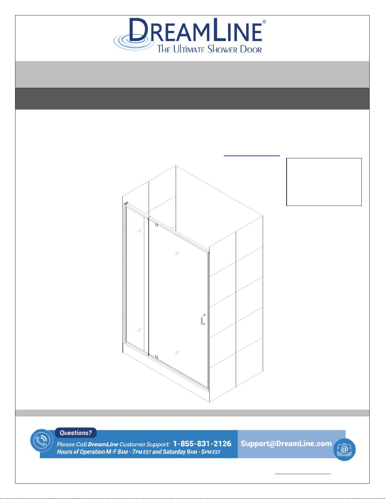
FLEX 28”x 72” / 32” x 72”
SHOWER DOOR INSTALLATION INSTRUCTIONS
Right hand door installation shown
Model#s:
SHDR-22287200-01
SHDR-22327200-01
Finish -01 = Chrome
IMPORTANT
DreamLine® reserves the right to alter, modify or redesign products at any time without prior
notice. For the latest up-to-date technical drawings, manuals, warranty information or any
other details, please refer to your model’s web page on DreamLine.com
FLEX Shower Door Manual Ver 2 Rev 8 01/2018 © 2018 DreamLine. All Rights Reserved
For more information about DreamLine® products please visit DreamLine.com
Page 2
2
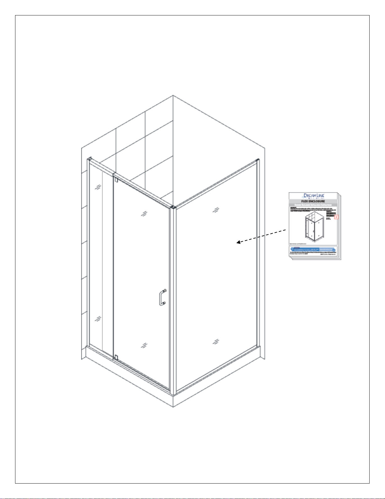
NOTE: This manual will describe the installation of the single threshold model of
the FLEX Shower Door.
For the FLEX Shower Enclosure installation, please also use the manual that is
packaged with the return panel glass.
FLEX Shower Door Manual Ver 2 Rev 8 01/2018 © 2018 DreamLine. All Rights Reserved
Page 3

3
Preparation
1. Prior to installation, examine all boxes and packages for shipping damage and compare the piece
count with your packing slip. After opening all boxes and packages read this introduction carefully.
Check that all of the needed parts are included in the package by checking off the components
on the “Detailed Diagram of Shower Door Components”. If the unit has been damaged, has a
finishing defect, or has missing parts, please contact our customer support department within
3 business days of the delivery date. Please note that DreamLine® will not replace any
damaged products or missing parts free of charge after 3 business days or if the product
has been installed. Feel free to contact DreamLine® if you have any questions, and please
provide an order number, job name or other proof of purchase to help us identify your original
order.
2. Please note that you should consult your local building codes with questions about
installation compliance standards. Building and plumbing codes may vary by location, and
DreamLine® is not responsible for code compliance standards for your project and will not
accept any returns.
3. If this unit is going to be installed in a new construction, please install all of the required
plumbing and drainage before installing the shower. Use a competent and licensed (if required
by local code) plumber for all plumbing installation.
4. Please make sure that prior to beginning the installation, the surfaces are leveled and solid and
will be able to support the total weight of the unit. Also make sure the walls are at right angles.
Irregular installation surface level, radius corners or improper angle of side walls will result in
serious problems for your installation. Please, note that some adjustments and drilling may be
necessary during the installation process.
5. Please protect all primary surfaces of the product during installation. Never set your glass down
directly onto a tile floor. Leave corner protectors in place until necessary to remove them.
Always use a piece of wood or cardboard to protect the bottom edge and corners of the glass
prior to and during installation.
6. This unit must be installed upon a finished threshold and against finished walls.
7. This model has 4” of total width adjustment: including 1/2” of adjustment per wall profile for out-of-
plumb wall conditions plus 3” of overall width adjustment with the expanding top and bottom rails.
Be sure that you have ordered the correct model size to fit your finished opening.
8. This model requires a minimum 1-3/8” of flat threshold space for installation.
9. Professional installation recommended.
NOTE: This door is reversible for right or left-hand door installation. The right-hand door installation is
shown as an example throughout this manual.
FLEX Shower Door Manual Ver 2 Rev 8 01/2018 © 2018 DreamLine. All Rights Reserved
Page 4
4
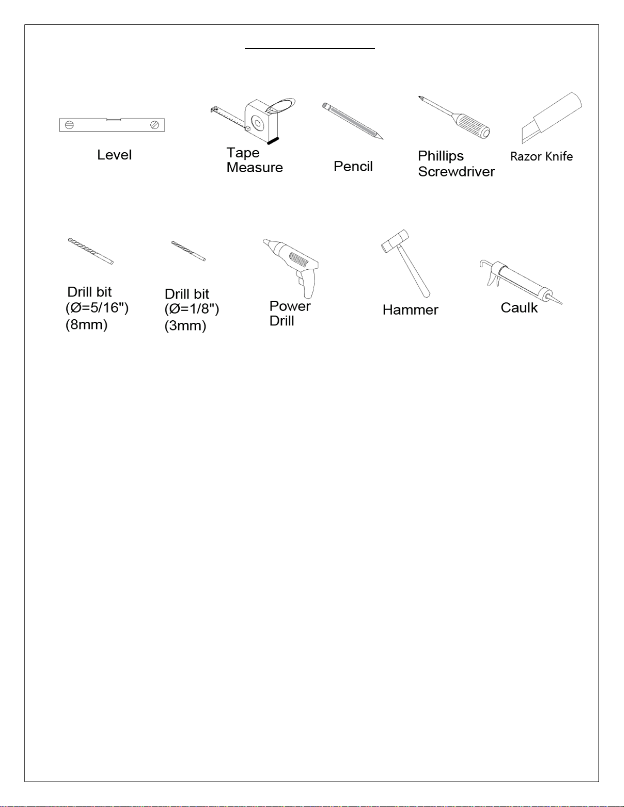
Tools Required
FLEX Shower Door Manual Ver 2 Rev 8 01/2018 © 2018 DreamLine. All Rights Reserved
Page 5
5
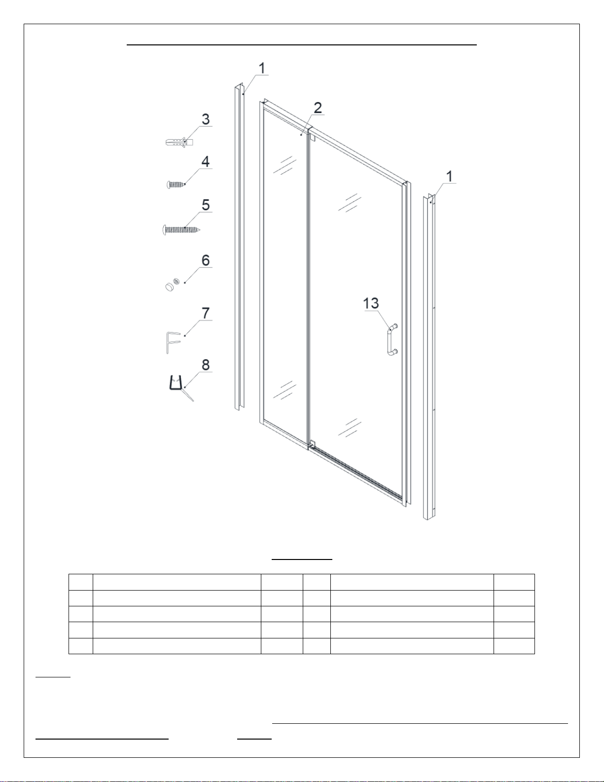
Detailed Diagram of Shower Door Components
01
Wall profile
2pcs
06
Decorative cap and washer
10pcs
02
Door assembly
1set
07
Flanged anti-water strip
1pc
03
Wall anchor
8pcs
08
Bottom anti-water strip
1pc
04
Round head screws ST4.2×10
10pcs
13
Handle
1pc
05
Truss head screws ST4.2×40
8pcs
NOTE: Unpack your unit carefully and inspect it. Lay it out and identify all parts using the detailed
diagram and packing list in this manual as a reference. Before discarding the carton, check for small
hardware bags that may have fallen to the bottom of the box. If any parts are damaged or missing,
please contact DreamLine® for replacement. The shipping boxes may contain extra parts not used in
your model configuration. NOTE: Retain these installation instructions for future reference.
FLEX Shower Door Manual Ver 2 Rev 8 01/2018 © 2018 DreamLine. All Rights Reserved
Part List
Page 6
6
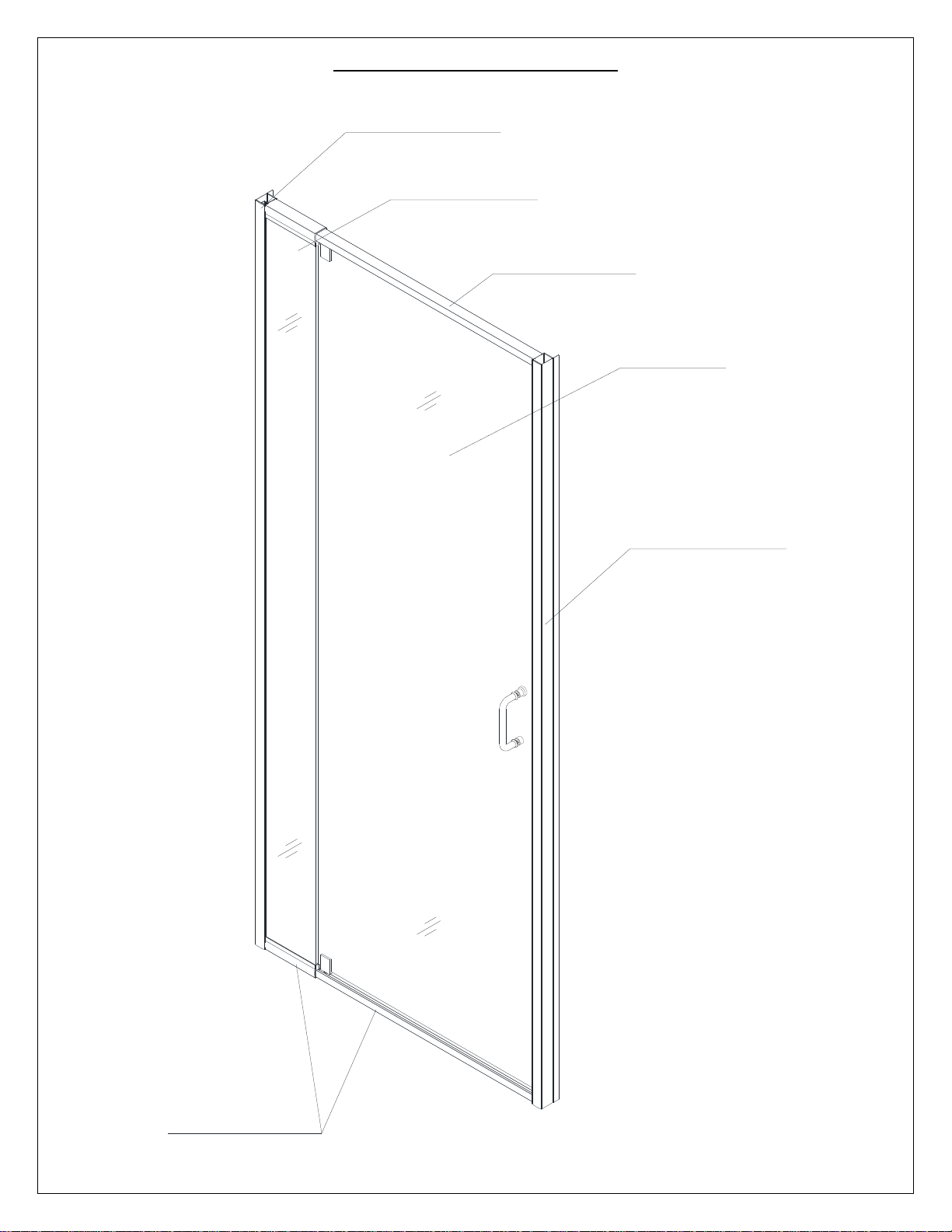
Alluminum profile
Expandable rail
Expandable rail
Glass door
Stationary glass
Alluminum profile
Door Assembly Diagram
FLEX Shower Door Manual Ver 2 Rev 8 01/2018 © 2018 DreamLine. All Rights Reserved
Page 7

7
Shower Door Installation
W
Fig. 1
Fig. 2
1. Prior to the Shower door installation, the installation of
the shower base and plumbing must be completed.
See Fig. 1 for details.
2. Slide the Wall profiles (01) over the Door assembly
(02) on both sides. Be sure that the flanges on the
Wall Profiles (01) face in towards the shower.
See Fig. 2 & Fig. 3 for details.
FLEX Shower Door Manual Ver 2 Rev 8 01/2018 © 2018 DreamLine. All Rights Reserved
Page 8

8
Fig. 3
1
2
Fig. 4
NOTE:
Flip the entire assembly for opposite installation.
3. Move the Door assembly (02) with the
Wall profiles (01) onto the Shower base
with the Stationary glass side tight to the
wall. Adjust the Door assembly (02) by
stretching the top and bottom Expanding
rails evenly to extend the Door assembly
(02) tight to the opposite wall. If the top
and bottom wall opening measurements
are different or if the walls are out-ofplumb, make adjustments by slightly
pulling the Wall profiles (01) out of the
Door assembly (02).
NOTICE:
The maximum adjustment width of the
Expanding rails is 3”. The wall profiles
allow for 1/2” adjustment for each side.
See Fig. 4 for details.
FLEX Shower Door Manual Ver 2 Rev 8 01/2018 © 2018 DreamLine. All Rights Reserved
Page 9

9
Fig. 6
Fig. 5
1
2
Inside
Inside
Outside
4. Adjust the Door assembly (02) so that it is
plumb by checking with a level.
See Fig. 5 for details.
5. Have an assistant hold the Door assembly (02) in the
correct position and mark the walls through the pre-drilled
holes in the flange of the Wall Profiles (01).
See Fig. 6 for details.
FLEX Shower Door Manual Ver 2 Rev 8 01/2018 © 2018 DreamLine. All Rights Reserved
Page 10

10
6. Set the Door assembly (02) aside; drill the holes using a
2
Ø 5/16”
1
Fig. 7
Ø5/16” drill bit and insert the Wall anchors (03).
See Fig. 7 for details.
7. Apply silicone along the Wall Profiles (01) and
around the holes on the wall.
Place the Wall Profiles (01) back on the Shower
base into the correct position and secure them to the
walls using the Truss head screws ST4.2×40 (05).
See Fig. 8 and Fig. 9 for details.
Fig. 8
FLEX Shower Door Manual Ver 2 Rev 8 01/2018 © 2018 DreamLine. All Rights Reserved
Page 11

11
Fig. 9
NOTE: If the finished opening width is at the
minimum for the model size, attach one wall
profile to the wall, set the door assembly
back into position on the threshold into the
installed wall profile and then attach the
remaining wall profile to the wall.
8. Place the Door assembly (02) back onto the
threshold.
See Fig. 10 for details.
Fig. 10
FLEX Shower Door Manual Ver 2 Rev 8 01/2018 © 2018 DreamLine. All Rights Reserved
Page 12

12
2
Note: Do Not lift the unit using the
handle as this could result in damage to
the glass and/or serious personal injury.
9. Install the Handle (13) onto the Door assembly (02).
Insert the Door assembly (02) with the Stationary glass
side into the Wall profile (01).
See Fig. 11 for details.
Fig. 10
Fig. 11
10. Extend the Door assembly (02) toward the
opposite wall and insert the Glass door side into
the Wall profile (01).
See Fig. 12 and Fig. 13 for details.
Fig. 12
FLEX Shower Door Manual Ver 2 Rev 8 01/2018 © 2018 DreamLine. All Rights Reserved
Page 13

13
Fig. 14
Fig. 13
11. Make sure the Door assembly (02) is fully extended into
the Wall profiles (01).
Adjust the top and bottom Expanding rails to the same
length so that the door opening is square.
Use a tape measure for accuracy.
See Fig. 14 for details.
FLEX Shower Door Manual Ver 2 Rev 8 01/2018 © 2018 DreamLine. All Rights Reserved
Page 14

14
Fig. 16
Fig. 15
Ø 1/8"
1
2
3
4
5
6
Ø 1/8"
Ø 1/8"
1
2
3
inside
inside
inside
inside
12. Drill holes into the top and bottom Expanding
rails through the predrilled holes using an Ø 1/8”
drill bit.
ATTENTION:
Do not drill all the way through the Expanding
rail, only through the first layer.
Secure the Expanding rails using the Round head
screws ST4.2×10 (04) and the raised white
washers.
Cover the exposed screw heads and washers with
the Decorative caps (06).
See Fig. 15 for details.
13. Make any final adjustments to the
Door assembly (02) with the Wall
profiles (01). Operate the Glass
door to make sure that the
magnetic strips create a good seal.
From inside the shower, drill holes
in the aluminum profile of the
Door assembly at the top and
bottom of the Wall profile using
an Ø 1/8” drill bit.
ATTENTION:
Do not drill all the way through
the Expanding rail, only through
the first layer.
Secure the Door assembly inside
the Wall profile using the Round
head screws ST4.2×10 (04) with
the raised white washers.
Cover the exposed screw heads
and washers with the Decorative
caps (06).
See Fig. 16 for details.
FLEX Shower Door Manual Ver 2 Rev 8 01/2018 © 2018 DreamLine. All Rights Reserved
Page 15

15
Caulk
Fig. 17
Fig. 18
outside
NOTE: Measure to the strike edge of the
door and notch the Bottom anti-water
strip (#08) with a razor knife to fit around
the magnet strip, leaving the bottom
sweep intact.
14. Attach the Flanged Anti-water strip (07) to the vertical edge of the
Stationary glass.
Open the door and attach the Bottom Anti-water strip (08) to the
bottom of the door glass from the pivot to the edge of the magnetic
strike rail and trim off the excess. Next, attach the cut off to the
bottom of the door glass, opposite of the pivot and trim to fit.
Attach both pieces of the Bottom Anti-water strip (08) to the
bottom edge of the Glass door.
See Fig. 17 for details.
15. Apply a good quality, mildew-resistant silicone along
the wall profiles and the bottom expanding rail
where they meet the walls and threshold from both
inside and outside the shower.
Allow 24 hours for the silicone to fully cure before
first use.
See Fig. 18 for details.
FLEX Shower Door Manual Ver 2 Rev 8 01/2018 © 2018 DreamLine. All Rights Reserved
Page 16

16
Product Maintenance
BASES and BACKWALLS: To ensure long lasting life for your acrylic back walls: wipe them off
after each use with a soft cloth. To clean the acrylic back walls use non-abrasive sprays or cream
based cleaners. Avoid the use of aerosol spray cleaners. Never use abrasive cleansers, metal
brushes or scrapers that could scratch or dull the surface.
GLASS: To ensure long lasting life for your glass shower products: wipe them off after each use
with a soft cloth. Rinse and wipe off the glass using either a soft cloth or a squeegee to prevent
soap buildup and water spots (Hard water can etch the surface of the glass over time if left to dry).
To prevent scratching the surface: never use abrasive cleaners or cleaning products that contain
scouring agents. Never use bristle brushes or abrasive sponges that may scratch the surface.
HARDWARE: To ensure a long lasting finish: wipe off the metal parts after each use with a soft
cloth. Do not use abrasive cleaners or cleaning products containing ammonia, bleach or acid. If
accidentally used, rinse the surface as soon as possible to prevent damage to the finish (peeling or
corrosion). After cleaning the polished finishes, rinse thoroughly and wipe dry with soft cloth.
Clean stainless steel surfaces at least once a week. When applying stainless steel cleaner or polish
to stainless steel hardware, work with (not across) the grain. Never use an abrasive sponge or cloth,
steel wool or wired brush as these may permanently scratch the surfaces.
NOTE: To maximize the life of your door, it is important to regularly inspect the glass and
other hardware for misalignment, proper attachment, and/or damage. Contact DreamLine
with any questions or concerns.
FLEX Shower Door Manual Ver 2 Rev 8 01/2018 © 2018 DreamLine. All Rights Reserved
Page 17

TEL: 866-731-2244
FAX: 866-857-3638
DREAMLINE.COM
For more information on DreamLine® Shower Doors and Enclosures please visit DreamLine.com
 Loading...