

DreamLine SHDR196058404, SHDR196058401, SHDR196072404, SHDR196072401, SHDR195472404 User Manual
...Page 1
MIRAGE-Z
SHOWER AND TUB DOOR INSTALLATION INSTRUCTIONS
IMPORTANT
®
DreamLine
For the latest up-to-date technical drawings, manuals, warranty information or additional details please refer
to your model’s web page on DreamLine.com
reserves the right to alter, modify or redesign products at any time without prior notice.
MODEL #s
SHDR-1960584-##
Right-Hand door installation shown
For more information about DreamLine
MIRAGE-Z shower and tub door manual Ver 1 Rev 1 02/2018
®
Shower Doors, Tub Doors & Enclosures, please visit DreamLine.com
MODEL #s
SHDR-1948724-##
SHDR-1954724-##
SHDR-1960724-##
©2018 DreamLine. All Rights Reserved
##=finish
01- Chrome
04- Brushed Nickel
Page 2

This model is treated with DreamLine’s
TM
exclusive ClearMax
Glass technology.
This is a specially formulated coating
that prevents the buildup of soap and
water spots.
Install the surface with the ClearMaxTM
label towards the inside of the shower.
Please note that depending on the
model, the glass may be coated on
either one or both surfaces.
For best results, squeegee the glass after
each use and dry with a soft cloth.
MIRAGE-Z shower and tub door manual Ver 1 Rev 1 02/2018
©2018 DreamLine. All Rights Reserved
Page 3
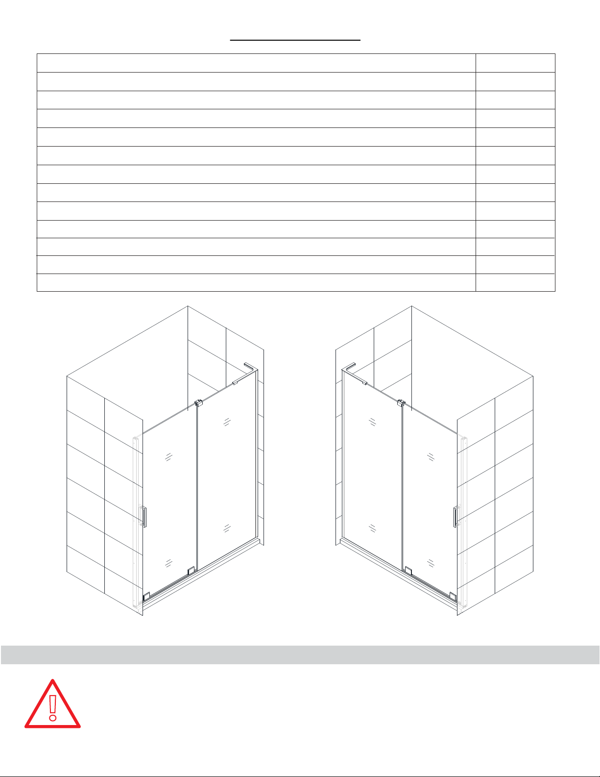
Table of Contents
Section title
Preparation
Model Diagram
Tools
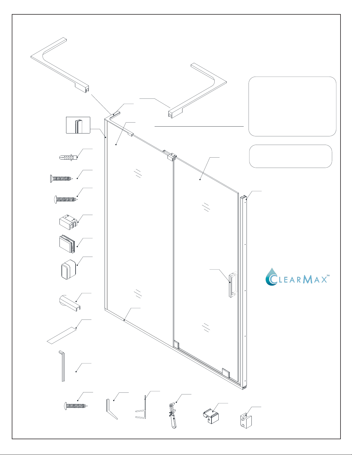
Detailed Diagram of Door Components
Parts List
Installation Steps
Safe Stop™ Bumpers Installation
L-Bar Installation
Bottom Roller Assembly
Guide Block Assembly
Vinyl Seals
Product maintenance
Page #
3
4
5
6
7
8-28
11-12
15-16
18-19
20
26
28
!
panel
panel
door
Right-Hand door installationLeft-Hand door installation
This model is reversible for either Left or Right-hand door installation.
The Right-hand door installation is shown an example throughout this instruction manual.
For a Left-hand door installation, simply reverse the orientation of the parts shown and use
the correct L-Bar™ for the installation.
door
MIRAGE-Z shower and tub door manual Ver 1 Rev 1 02/2018
2
Page 4

Preparation
1. Prior to installation, examine all boxes and packages for shipping damage and compare the piece count with
your packing slip. After opening all boxes and packages read this introduction carefully. Check that all of the
needed parts are included in the package by checking off the components on the “Detailed Diagram of Shower
Door Components”. If the unit has been damaged, has a finishing defect, or has missing parts, please contact our
customer support department within 3 business days of the delivery date. Please note that DreamLine
replace any damaged products or missing parts free of charge after 3 business days or if the product has
been installed. Contact DreamLine
other proof of purchase to help identify the original order.
®
if you have any questions, and please provide an order number, job name or
®
will not
2. Please note that you should consult your local building codes with questions on installation
compliance standards. Building and plumbing codes may vary by location, and DreamLine
responsible for code compliance standards for your project and will not accept any returns.
3. If this unit is going to be installed in a new construction, please install all of the required plumbing and drainage
before installing the shower. Use a competent and licensed (if required by local code) plumber for all plumbing
installation
4. Make sure that prior to beginning the installation, the surfaces are leveled and solid and will be able to support
the total weight of the unit. Also make sure the walls are at right angles. Irregular installation surface level, radius
corners or improper angle of side walls will result in serious problems for your installation. Please, note that some
adjustments and drilling might be necessary during the installation process.
5. Protect all primary surfaces of the product during installation. Never set your glass down directly onto a tile
floor. Leave corner protectors in place until necessary to remove them. Always use a piece of wood or cardboard
to protect the bottom edge and corners of the glass prior to and during installation.
6. This unit must be installed upon a finished threshold and against finished walls.
7. This model can be adjusted up to 3/8” on the panel side only for out-of-plumb conditions within the
u-channel. Verify that the walls are plumb before proceeding with the installation.
8. This model requires that you drill into the threshold for proper installation.
®
is not
9.
This model requires a minimum 1-1/2”of flat threshold space for installation.
10. This model requires two installers.
11. Professional installation recommended.
12. This model ships with both the LEFT and RIGHT hand L-Bar™ for support. Use the correct L-Bar
based on the handing of the installation.
NOTE: DO NOT attach the handle to the door glass or the towel bar to the panel glass until
instructed.
!
!
MIRAGE-Z shower and tub door manual Ver 1 Rev 1 02/2018
DO NOT use the handle or towel bar to lift the glass during installation. This may result in
damage to the glass and/or serious injury. Always use an assistant or a professional grade
glass suction cup when handling heavy glass.
NOTE: This model is available in either a shower height or a tub height. This manual will
describe the installation steps showing a shower height model. Please follow the same
sequence of installation steps for the tub height model installation.
©2018 DreamLine. All Rights Reserved
3
Page 5
Model Diagram
L - Bracket
11
PANEL
5
DOOR
9
!
4
11
10
Right-Hand door installation
using the left-hand L-Bar
is shown as an example
through out this manual
©2018 DreamLine. All Rights Reserved
4MIRAGE-Z shower and tub door manual Ver 1 Rev 1 02/2018
Page 6
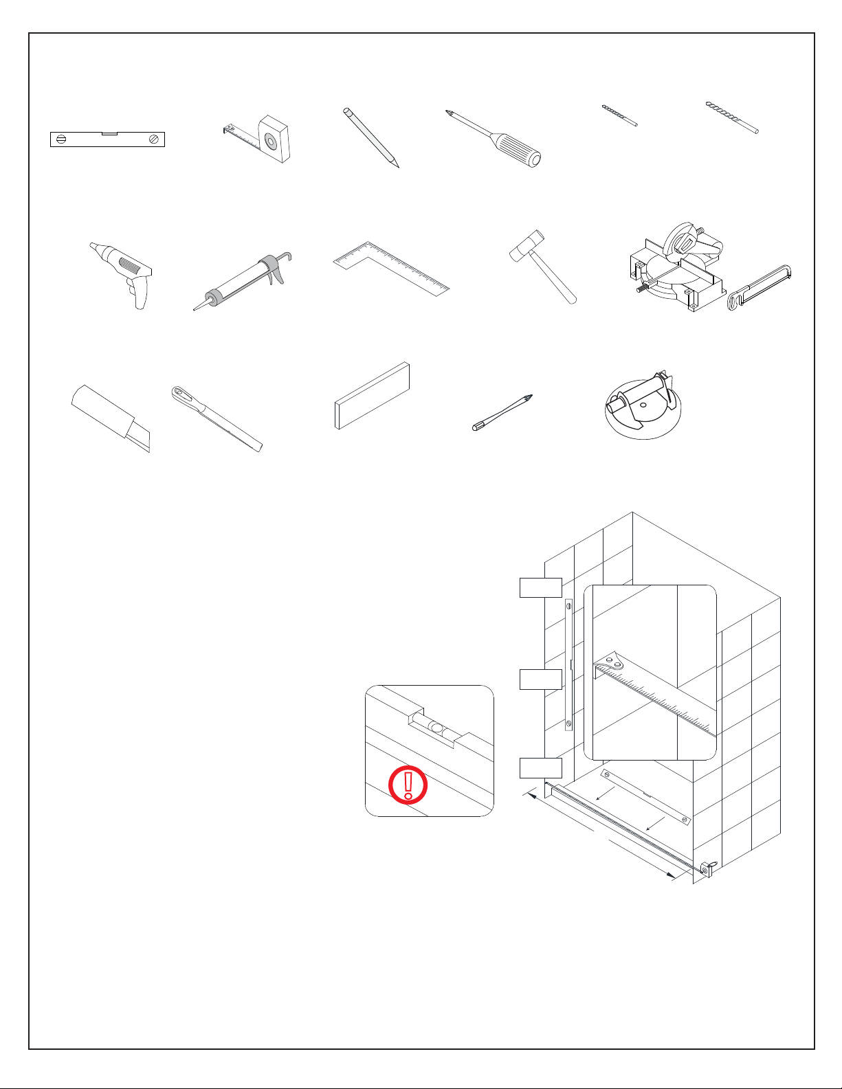
Tools
Level
Power
Drill
Razor Knife
Tape
Measure
Silicone
Metal File
Pencil
Carpenter's
Square
1/4” wood or
plastic shim
Phillips
Screwdriver
Soft Head
Hammer
Phillips extender
driver bit
Drill bit
Ø1/8"
(3mm)
Miter saw and Hacksaw
Professional-grade
Glass suction cup
Drill bit
Ø5/16"
(8mm)
Top
Tip: Measure the finished opening before
proceeding with the installation to be sure
that the correct model size has been
ordered.
Threshold must be level.
Middle
Tip: Prior to installation, cover the
shower/tub drain with tape to prevent
losing screws or small parts.
Bottom
!
Tip: Set screw gun clutch to low setting
when installing screws and bolts to
prevent stripping the heads.
NOTE: Unpack your unit carefully and inspect it. Lay it out and identify all parts using the detailed
diagram and packing list in this manual as a reference. Before discarding the carton, check for small
hardware bags that may have fallen to the bottom of the box. If any parts are damaged or missing,
please contact DreamLine
your model configuration.
®
for replacement. The shipping boxes may contain extra parts not used in
W
NOTE: Retain these installation instructions for future reference.
©2018 DreamLine. All Rights Reserved
5MIRAGE-Z shower and tub door manual Ver 1 Rev 1 02/2018
Page 7
L-Bar™ (Left)
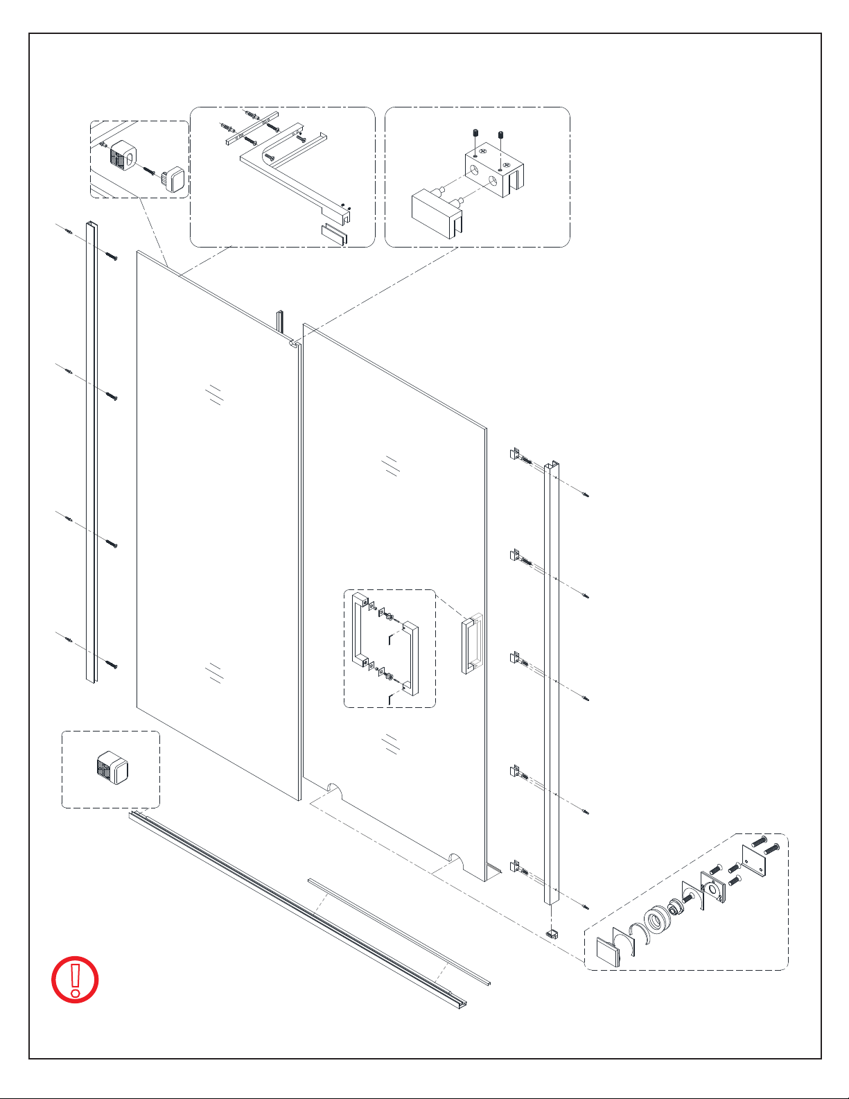
Detailed Diagram of shower door components
NOTE: The left hand L-Bar™
installation is shown as an
example throughout this
manual. Follow the same
steps for installing the
Right-hand L-Bar™.
12” L-Bar™ for 48” model
18” L-Bar™ for 60” models
7
6
17
5
1
5
L-Bar™ (Right)
2
8
9
10
11
12
14
PANEL
3
22
DOOR
4
The glass surface
with the ClearMax™
label must be
installed to face
inside of the shower
15
16
18
19
20
21
23
©2018 DreamLine. All Rights Reserved
6MIRAGE-Z shower and tub door manual Ver 1 Rev 1 02/2018
Page 8

Parts List
ITEM#
01
02
03
04
05*
06
07
08
09
10
PART NUMBER
4872
6058
6072
4872
6058
6072
04170011-1269 /
48"
04170011-1574 / 04170041-1574
60"
07221042 /
07121058 / 07121059
07124058 / 07124059
07550045
092108
091105
07011102 /
07311019 /
010260001
010260002
010260003
010260004
010260005
010260006
04170041-1269
07224042
07014102
07314019
DESCRIPTION
Stationary Panel Glass
Door Glass
Bottom Guide Rail
Handle (203mm centers)
L-Bar™ (Left and Right) (12” or 18”)
Ø8mm (5/16”) Plastic Wall Anchor
Countersunk screw ST4.2x40
Truss Head screw ST4.2x30
Top Guide Block
Bottom Roller Assembly
QTY
1pc
1pc
1pc
1pc
1 set of 2 (L/R)
15pcs
pcs
12
3pcs
1pc
2pcs
11
12
14
15
16
17
18
19
20
21
22
07021154 /
07121080 / 07124080
48"
07121081 / 07124081
60"
07550091
098002 / 098003
091107
72"
07121085 / 07124085
07121086 / 07124086
58"
63023000-0503
48"
63023000-0648
60"
063002100-1804
72"
063002100-1447
58"
098008
07551075
07121087 / 07124087
72"
07121088 / 07124088
58"
07024154
SafeStop™ Bumper
Bottom Rail insert
0.5mm Bottom Spacer Strip
Allen Wrench: 2.5mm and 3mm
Truss Head screw ST4.2x40
Wall profile A (for panel glass)
Deflector
(w/adhesive)
Anti-Water Side Strip x1804mm /
Roller Adjustment tool
U-Channel support
Wall profile B (for door glass)
(71”)
2pcs
1pc
1pc
1each
3pcs
1pc
1pc
1pc
1pc
1pc
1pc
23
BOLD digit indicates finish color: 1= Chrome, 4= Brushed Nickel
* The 12” L-Bar™ (#05) is used with the 48” model. The 18” L-Bar™ (#05) is used with the 60” models (shower and tub)
MIRAGE-Z shower and tub door manual Ver 1 Rev 1 02/2018
07550074
PVC Bumper inserts
5pcs
©2018 DreamLine. All Rights Reserved
7
Page 9
Installation steps
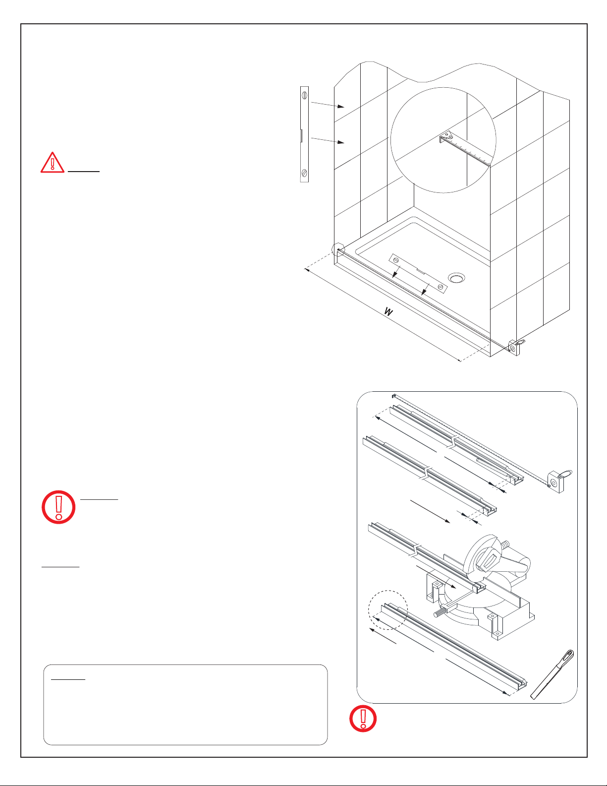
1. Measure the finished opening at the top,
middle and bottom.
The bottom width dimension will be “W”.
Also check the threshold for level and the
walls for plumb.
!
NOTE that this model will provide up
to 3/8” of adjustment for out-of-plumb
conditions within the U-Channel on the
stationary panel side only. (Fig 1)
This model requires a minimum
threshold width of 1-1/2”
Fig 1
2. Subtract 1/16” from the “W” dimension.
(W (-) 1/16” = L) “L” = finished cut length.
Use a miter saw or hack saw to cut your Bottom
Guide Rail (#03) to the finished cut length “L”. Use a
metal file to file off any burrs from the cut end of the
Bottom Rail. (Fig 2)
NOTE: Only cut from the end of the
bottom rail that will be installed on the
!
door side of the opening.
NOTE: The Bottom Guide Rail (#03) is made 2” larger
than the model size:
(48” model = 50” bottom rail, 60” model = 62” bottom rail).
The rail is milled at both ends to accomodate the bottom
bumper for the panel side. This milling will be cut off on the
door-end when the bottom rail is cut to size to fit the
finished opening.
L
door end
door end
panel end
L
NOTE: If it is necessary to drill new attachment
holes into the bottom guide rail after cutting to
size: drill a Ø3/16” hole throughout and then a
Ø5/16” hole through the top layer only. (Refer to
the existing holes in the rail for example)
MIRAGE-Z shower and tub door manual Ver 1 Rev 1 02/2018
Bottom Rail cut for right-hand door
installation shown as an example
!
Fig 2
©2018 DreamLine. All Rights Reserved
8
Page 10

3. Attach the U-Channel Support Block (#21) to the
door end of the Bottom Guide Rail (#03). (Fig 3)
threshold
Bottom Rail cut for
right-hand door installation
shown as an example
door end of rail
Fig 3
4. Place the Bottom Guide Rail (#03)
onto the threshold and mark its position.
Use a tape measure to keep the Bottom
Guide Rail (#03) parallel with the outside
edge of the threshold. (Fig 4)
Fig 4
5. Mark the position of the holes on the threshold through the
holes in the Bottom Guide Rail (#03).
*NOTE: Use a power drill to make the holes using:
◾ Ø1/8” drill bit (for installation into an acrylic threshold)
◾ Ø5/16” drill bit (using anchors into a tile threshold)**
Apply silicone to the underside of the Bottom Guide Rail (#03)
and attach it to the threshold using:
◾ ST4.2 x 30mm Truss Head screws (#16) for an acrylic
threshold.
OR
◾ ST4.2 x 40mm Truss Head screws (#21) (with **anchors
for tile).
(Fig 5)
1
**Ø1/8"
or Ø5/16”
**3
**Use anchors for
installation into a
tile threshold only
2
4
Fig 5
©2018 DreamLine. All Rights Reserved
9MIRAGE-Z shower and tub door manual Ver 1 Rev 1 02/2018
Page 11

6. Position the
against the wall, on top of the Bottom Guide Rail
(#03), and flush with the outside of the Bottom Guide
Rail (#03). Adjust to plumb using a level.
Mark the
on the wall. (Fig 6)
Wall Profile A (panel side)
Wall Profile A (panel side)
(#17) position
(#17)
Fig 6
7. Mark the hole locations for drilling through the holes in the
Remove the
Wall Anchors (#06). Apply a bead of silicone to the wall or to the back of the
side)
(#17).
Attach the
1
Wall Profile A (panel side)
Wall Profile A (panel side)
2
Ø5/16"
(#17) and drill Ø5/16”(6mm) holes into the wall. Insert the
(#17) to the wall using the ST4.2 x 40 screws (#07). (Fig 7)
3
Wall Profile A (panel side)
4
(#17).
Wall Profile A (panel
5
Fig 7
©2018 DreamLine. All Rights Reserved
10MIRAGE-Z shower and tub door manual Ver 1 Rev 1 02/2018
Page 12

NOTE: The top Safe Stop™ Bumper (#11) must be
screwed to the wall beneath the L-Bar™ (#05) and
against the
The bottom Safe Stop™ Bumper (#11) is installed
with 3M tape only. Attaching the bottom Safe Stop™
Bumper (#11) with a screw is optional.
(Fig 8, Fig 9a and Fig 9b)
Wall Profile/U-Channel
(#17).
11
11.2
11.4
11.3
11.1
3M tape
Safe Stop™ Bumper #11 parts list
Phillips extender driver bit
recommended
for screw installation
11.1
11.2
11.3
11.4
Bumper insert
Bumper base
ST4.2x40
Wall Anchor
1pc
1pc
1pc
1pc
8. To install the top Safe Stop™ Bumper (#11): Remove the Bumper Insert (#11.1) and hold the
Bumper Base (#11.2) in place 1” below the top and against the
(Fig #7.1) to mark the position on the wall and to mark the hole for drilling.
Drill a Ø5/16” hole and insert a Wall Anchor (#11.4). Clean the area with an alcohol swab. Remove
the 3M tape backing from the Safe Stop™ Bumper (#11). Install the Bumper Base (#11.2) with
the ST4.2 x 40 Screw (#11.3) and replace the Bumper Insert (#11.1). (Fig 8)
1
2
bumper
u-channel
1”
3
Wall Profile/U-Channel
4
Ø5/16"
(#17)
5
6
Remove the 3M tape
backing
Fig 8
7
8
©2018 DreamLine. All Rights Reserved
11MIRAGE-Z shower and tub door manual Ver 1 Rev 1 02/2018
Page 13

9. To install the bottom Safe Stop™ Bumper (#11): First, clean the area with an alcohol swab. Remove
the 3M tape backing from the Safe Stop™ Bumper (#11) and install the Safe Stop™ Bumper (#11)
onto the Bottom Rail (#03) firmly against the wall and the
(Fig 9a and Fig 9b)
NOTE: Drilling a Ø5/16” hole and using an anchor to
!
attach the bottom Safe Stop™ Bumper (#11) is optional.
Wall Profile/U-Channel
(#17).
1
Remove the 3M tape
backing
2
inside
Fig 9a
u-channel
bottom rail
inside
Fig 9b
©2018 DreamLine. All Rights Reserved
12MIRAGE-Z shower and tub door manual Ver 1 Rev 1 02/2018
Page 14

10. Apply silicone into the
and into the Bottom Guide Rail (#03) equal to the width
of the panel glass. (Fig 10)
Wall Profile/U-Channel
(#17)
Width of
Panel Glass
Caulk
Fig 10
11. Cut the 0.5mm Bottom Spacer Strip (#14) into four to five 2” pieces and place them into the
Bottom Guide Rail (#03) (after the silicone) to protect the bottom edge and corners of the Stationary
Panel Glass (#01). (Fig 11)
DO NOT install one long continuous strip into the bottom rail.
!
cut 2”pcs
0.5mm Bottom Spacer Strip (#14)
Fig 11
©2018 DreamLine. All Rights Reserved
13MIRAGE-Z shower and tub door manual Ver 1 Rev 1 02/2018
Page 15

Right-hand door installation shown
12. After applying silicone into the Bottom Guide
Rail (#03), add the 2” pieces of the 0.5mm
Bottom Spacer Strip (#14) into the Bottom
Guide Rail (#03) to protect the bottom edge and
corners of the Stationary Panel Glass (#01).
(Fig 12)
Width of
Panel Glass
13. Install the Stationary Panel Glass (#01) into
Wall Profile/U-Channel
the
Guide Rail (#03). (Fig 13)
(#17) and Bottom
!
NOTE: The panel-side
will allow for up to 3/8” of out-of-plumb adjustment.
Use a level to confirm that the Stationary Panel
Glass (#01) is installed plumb and level.
Wall Profile/U-Channel
(#17)
Fig 12
1
2
Fig 13
©2018 DreamLine. All Rights Reserved
14MIRAGE-Z shower and tub door manual Ver 1 Rev 1 02/2018
Page 16

14. After the Stationary Panel Glass (#01) is installed into the
Wall Profile/U-Channel
the appropriate (Left or Right) L-Bar™ (#05) as described in the following steps. (Fig 14)
(#17), install
Left L-Bar™ installation shown as an example
5.4
5
5.5
5.6
5.7
5.8
5.3
5.2
5.1
Fig 14
L-Bar parts list
5.1
Rubber pad
M5 rubber tip set screw
5.2
L-Bar
5.3
Decorative cover
5.4
Wall Anchor
5.5
Wall plate
5.6
ST4.2x40
5.7
M5x14.5 Screw
5.8
12” L-Bar™ for 48” model
18” L-Bar™ for 60” models
2pcs
2pcs
1pc
1pc
2pcs
1pc
2pcs
2pcs
Left L-Bar installation shown as an example
©2018 DreamLine. All Rights Reserved
15MIRAGE-Z shower and tub door manual Ver 1 Rev 1 02/2018
Page 17

15. Use a level and position the L-Bar™ (#05) onto the Stationary Panel Glass (#01) as shown and
mark the position on the wall. Remove the Wall Plate (#5.6) and mark the holes for drilling. Drill two
Ø5/16”(8mm) holes and insert the Wall Anchors (#06). Attach the Wall Plate (#5.6) using ST4.2 x 40
(#5.7) screws. (Fig 15)
TIP: Leave the decorative
!
cover attached when
marking the L-Bar
postion on the wall to
allow space to re-attach
the cover plate after
installation.
1
5
2
Ø5/16"
(8mm)
6
Fig 15
3
4
7
16. Attach the L-Bar™ (#5.3) to the Wall Plate
(#5.6) and adjust the angle (+/-) 3/16” (4mm) if
necessary using the set screws (Fig 16.3 and 16.4).
Secure the L-Bar™ (#05) to the top of the
Stationary Panel Glass (#01) using the clear
gasket and rubber-tipped set screws. Firmly tighten
the set screws and re-attach the Decorative Cover
(#5.4). (Fig 16)
1
Max 3/16” (4mm)
4
2
5
”(
0-1/16
Fig 16
2mm)
3
Max 3/16”(4mm)
6
©2018 DreamLine. All Rights Reserved
16MIRAGE-Z shower and tub door manual Ver 1 Rev 1 02/2018
Page 18

17. Measure from the edge of the installed Stationary Panel Glass (#01) to the wall and cut the
Bottom Rail Insert (#12) to this dimension: W (-) 1/16”. Use a metal file to file off any burrs from the
cut end. Apply silicone into the Bottom Guide Rail (#03) and install the Bottom Rail Insert (#12).
(Fig 17)
W
W
Trim the insert to: W (-) 1/16”
0.5mm Bottom
Spacer Strip
NOTE: Insert a small section (1/4”+/-) of the leftover 0.5mm
Bottom Spacer Strip (#14) between the end of the Bottom
!
Rail Insert (#12) and the Stationary Panel Glass (#01) to
prevent glass-to-metal contact.
W
Fig 17
(#14)
©2018 DreamLine. All Rights Reserved
17MIRAGE-Z shower and tub door manual Ver 1 Rev 1 02/2018
Page 19

Bottom Roller Assembly (#10)
Parts List
10.1
10.2
10.3
10.4
10.5
10.6
10.7
10.8
10.9
Roller body (exterior)
Rubber pad 1
Rubber pad 2
Bearing
Adjustment disk
M5x14 Allen Bolt
Cover plate
Decorative cover plate
M5x16 Allen Bolt
1pc
2pcs
1pc
1pc
1pc
4pcs
1pc
1pc
2pcs
10.9
10.6
10.8
10.6
10.7
10.5
10.4
10.3
10.2
10.1
NOTE: It is not necessary to completely
disassemble the wheel assembly
during installation
NOTE: DO NOT install the handle onto the door glass until instructed.
!
DO NOT lift the glass using the handle. This could result in damage to the glass
and /or serious personal injury. Always use an assistant or a professional grade
glass suction cup when handling heavy glass.
18. Remove the M5 x 16 Allen Bolts (#10.9) and the Cover Plate (#10.7).
Remove the three M5 x 14 Allen Bolts (#10.6) and attach the Roller Assemblies (#10) to the
Door Glass (#02). Make certain that the bolts are facing the inside of the shower and that the
roller assembies are installed squarely onto the glass.
Door Glass
(Fig 18a and Fig 18b)
Fig 18a
1/8”
1/8”
inside of shower
Fig 18b
©2018 DreamLine. All Rights Reserved
18MIRAGE-Z shower and tub door manual Ver 1 Rev 1 02/2018
Page 20

!
19. Set the Door Glass (#02) with the attached Bottom Roller Assemblies (#10) onto the Bottom
Guide Rail (#03). Have an assistant support the Door Glass (#02) for the next few steps. (Fig 19)
!
NOTE: Have an assistant available to hold the door glass in position during the next
steps until the door is secured in position with the Guide Block Assembly (#09).
NOTE: Use caution to prevent the door glass from making contact with the installed
panel glass or the wall during installation.
Fig 19
©2018 DreamLine. All Rights Reserved
19MIRAGE-Z shower and tub door manual Ver 1 Rev 1 02/2018
Page 21

Guide Block Assembly (#09)
Parts List
9.1
Exterior Slider Bracket (for panel)
9.2
Gasket
1pc
2pcs
9.8
9
9.7
Rubber sleeve
9.3
9.4
9.5
9.6
9.7
9.8
20. Loosen the
Shaft
Sliding pad
Sliding Guide Block (for door)
M5x10 set screw
M4x4 flat head screw
M5x10 set screws
seperate the bracket.
Attach the Exterior Slider
2pcs
2pcs
1pc
1pc
2pcs
2pcs
(#9.7) to
Bracket (#9.1) through the notch of the installed
Stationary Panel Glass (#01) as shown in Fig
20a.1 using the Gasket (#9.2) and Rubber
Sleeves (#9.3).
Next, while holding the Door Glass (#02) in place,
position the Sliding Guide Block (#9.6) onto the
Door Glass (#02), align and attach the two halves
of the Guide Block (#09) with the M5 x 10 set
screws (#9.6) using Allen Wrench (#15)
(Fig 20a and Fig 20b)
9.6
9.2
9.3
9.4
9.1
NOTE: It is not necessary to completely
disassemble the guide block assembly
during installation
loosen
9.5
1
2
Fig 20a
Fig 20b
©2018 DreamLine. All Rights Reserved
20MIRAGE-Z shower and tub door manual Ver 1 Rev 1 02/2018
Page 22

21. Install the Handle (#04) through the holes in the Door Glass (#02). Be sure that the pvc gaskets
and sleeves are in place. (Fig 21)
1
2
inside inside
Fig 21
22. Position the Wall Profile B (door side) (#22) against the wall and onto the U-Channel Support
Block (#21) on the door-side of the opening. (Fig 22)
Fig 22
©2018 DreamLine. All Rights Reserved
21MIRAGE-Z shower and tub door manual Ver 1 Rev 1 02/2018
Page 23

23. Partially insert at least two of the PVC Bumper Inserts (#23)
into Wall Profile B (door side) (#22) for accurate alignment.
Close the door into the profile. Use a level to hold the Wall
Profile B (door side) (#22) plumb and mark the position of the
Wall Profile B (door side) (#22) on the wall. (Fig 23)
Partially insert at least two of the PVC
Bumper Inserts (#23) at the top and
!
bottom of the Wall Profile B for accurate
alignment with the door glass. Do not cover the
holes that need to be marked on the wall.
Failure to use these inserts when aligning the
Wall Profile B may result in misalignment with
the Door Glass.
24. Remove the PVC Bumper Inserts (#23). Mark the holes for drilling
through the larger holes in the Wall Profile B (door side) (#22).
(Fig 24)
Fig 23
Fig 24
©2018 DreamLine. All Rights Reserved
22MIRAGE-Z shower and tub door manual Ver 1 Rev 1 02/2018
Page 24

25. Remove the
Insert the Wall Anchors (#06).
Apply a bead of silicone to the back of the
Attach the
Use a 1/4” thick wooden or plastic shim to fully press the PVC Bumper Inserts (#23) into the smaller
holes in Wall Profile B
(Fig 25)
Wall Profile B (door side)
Wall Profile B (door side)
(#22) to the wall using the ST4.2 x 40 Screws (#07).
(door side)
(#22).
(#22) and drill Ø5/16”(6mm) holes into the wall.
Wall Profile B (door side)
(#22).
1
5
2
6
Ø5/16"
3
7
4
8
Fig 25
TIP: Use a 1/4” thick wood or plastic shim to
fully press the PVC Bumper Inserts (#23) into
the Wall Profile B (door side) (#22) (Fig 25.6)
©2018 DreamLine. All Rights Reserved
23MIRAGE-Z shower and tub door manual Ver 1 Rev 1 02/2018
Page 25

26. The door should operate smoothly and create a good seal
within the
closed position.
If necessary, adjust the Bottom Rollers (#10) to tilt the
door slightly for a tight fit into the PVC Bumper Inserts (#23)
To adjust the rollers: Loosen the center M5 x 14 Allen Bolts
(#10.6) and then rotate the Adjustment Disk (#10.5) using
the Roller Adjustment Tool (#20) as shown below.
Use shims or an assistant to hold the Door Glass (#02) in the
desired position and re-tighten the allen bolt.
Only adjust one roller at a time. (Fig 26a and Fig 26b)
!
Wall Profile B (door side) (#22) when in the fully
Use shims beneath the door glass during
adjustment to prevent the door glass from
making contact with the bottom rail.
2 rotate 3 tighten1 loosen
.
Right-hand door installation
as viewed from the inside
Fig 26a
Amount of adjustment:
neutral
3/16”(4.5mm)
1/16”
max. 1/4”(6.5mm) min.1/16”(2.5mm)
1/16”
Fig 26b
©2018 DreamLine. All Rights Reserved
24MIRAGE-Z shower and tub door manual Ver 1 Rev 1 02/2018
Page 26

27. Attach the roller Cover Plate (#10.8), leaving approximately 1/16” of clearance beneath the
bottom rail. Re-adjust the plate if it makes contact with the bottom rail. (Fig 27)
Fig 27
1/16” gap
©2018 DreamLine. All Rights Reserved
25MIRAGE-Z shower and tub door manual Ver 1 Rev 1 02/2018
Page 27

28. Remove the paper strip from the adhesive backing on the Bottom Deflectors (#18) and attach all
three deflectors to the bottom edge of the Door Glass (#02) as shown.
the
Bottom Deflector (#18) on the closing side of the Door may need to be trimmed during installation to fit
up to the Wall Profile B (#22).
Attach the Anti-Water Side Strip (#19) to the edge of the Door Glass (#02).
Notch the top to fit around the L-Bar™ and notch the bottom to fit around the Bottom Deflector (#18).
(Fig 28)
Based on the opening conditions,
!
NOTCH OUT TO FIT
AROUND THE BOTTOM
DEFLECTOR VINYL
BOTTOM DEFLECTOR (3 PCS)
Fig 28
This deflector may need to be trimmed during
installation to fit up to the Wall Profile B based
on the opening conditions.
Right-hand door installation
as viewed from the inside
©2018 DreamLine. All Rights Reserved
26MIRAGE-Z shower and tub door manual Ver 1 Rev 1 02/2018
Page 28

29. Apply a good quality, mildew-resistant silicone along both vertical channels and the bottom rail
from inside the shower. (Fig 29)
!
Allow 24 hours for the silicone to cure before using the shower.
24
Hours
24
Hours
P
ANEL
D
OOR
Fig 29
OOR
D
ANEL
P
©2018 DreamLine. All Rights Reserved
27MIRAGE-Z shower and tub door manual Ver 1 Rev 1 02/2018
Page 29

Product Maintenance
BASES and BACKWALLS: To ensure long-lasting life for your acrylic back walls, wipe them off
after each use with a soft cloth. To clean the acrylic back walls use non-abrasive sprays or cream
based cleaners. Avoid the use of aerosol spray cleaners. Never use abrasive cleansers, metal
brushes or scrapers that could scratch or dull the surface.
GLASS: To ensure long-lasting life for your glass shower products, wipe them off after each use
with a soft cloth. Rinse and wipe off the glass using either a soft cloth or a squeegee to prevent
soap buildup and water spots (Hard water can etch the surface of the glass over time if left to
dry). To prevent scratching the surface: never use abrasive cleaners or cleaning products that
contain scouring agents. Never use bristle brushes or abrasive sponges that may scratch the
surface.
HARDWARE: To ensure a long-lasting finish, wipe off the metal parts after each use with a soft
cloth. Do not use abrasive cleaners or cleaning products containing ammonia, bleach or acid. If
accidentally used, rinse the surface as soon as possible to prevent damage to the finish (peeling
or corrosion). After cleaning the polished finishes, rinse thoroughly and wipe dry with a soft
cloth.
Clean stainless steel surfaces at least once a week. When applying stainless steel cleaner or
polish to stainless steel hardware, work with (not across) the grain. Never use an abrasive
sponge or cloth, steel wool or wired brush as these may permanently scratch the surfaces.
NOTE: To maximize the life of your door, it is important to regularly inspect
the glass and all hardware for misalignment, proper attachment, and/or
damage. Contact DreamLine
®
DreamLine
shower doors and enclosures are designed not to leak when
®
with any questions or concerns.
installed properly and the flow of water is not pointed directly at the vinyl
seals.
©2018 DreamLine. All Rights Reserved
28MIRAGE-Z shower and tub door manual Ver 1 Rev 1 02/2018
Page 30

For more information on DreamLine
TEL: 866-731-2244
FAX: 866-857-3638
DREAMLINE.COM
®
Shower Doors and Enclosures please visit DreamLine.com
©2018 DreamLine. All Rights Reserved
 Loading...