

Page 1
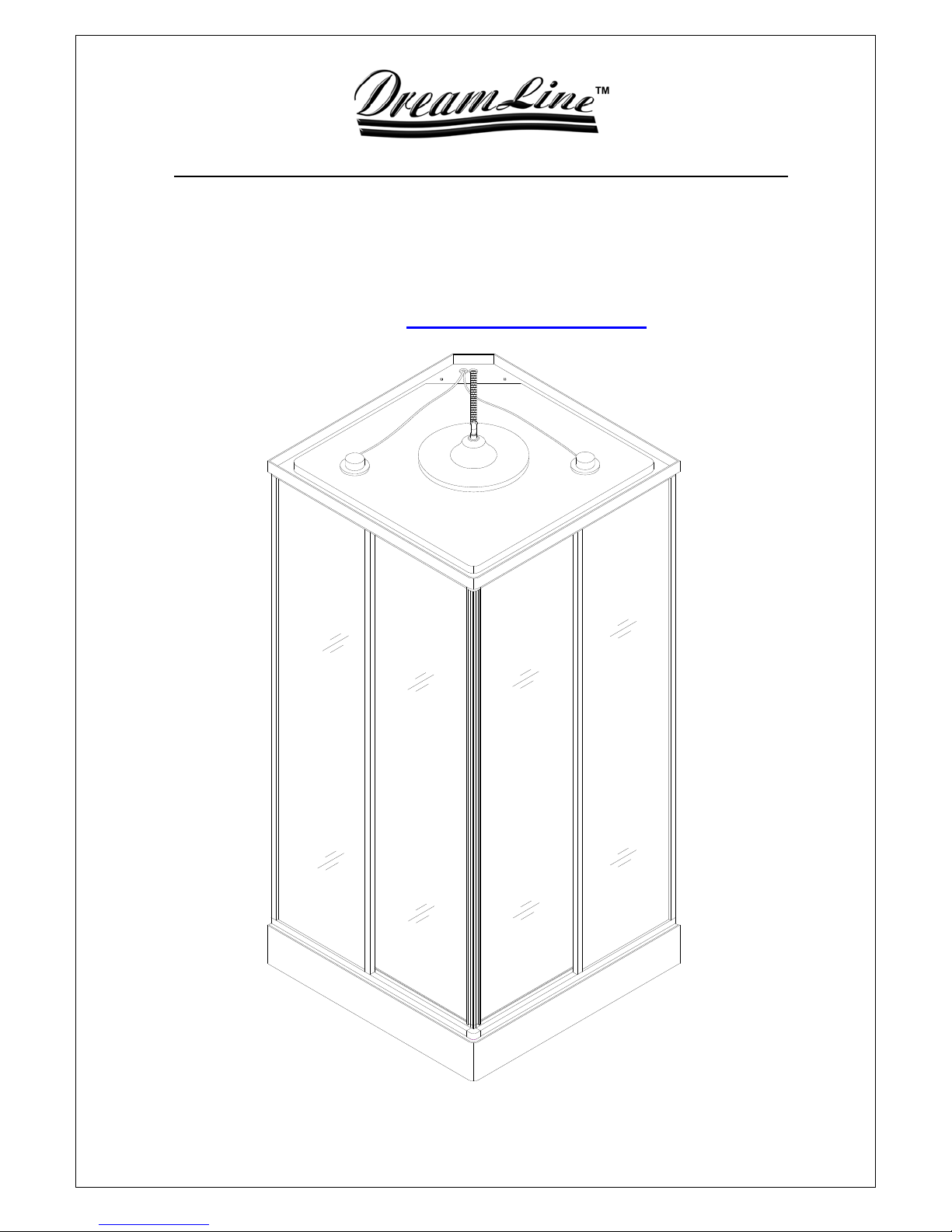
Reflection
Steam room Installation Instructions
IMPORTANT
Please read carefully the following instructions before installing your shower cabin. If you
have any questions on this shower cabin installation - please call our technical support
specialists Monday to Friday 9:00AM – 5:00PM EST at 1-866-731-8378 Option 3 or email our technical support group at support@BathAuthority.com
Our product may have changes without prior notice
Page 2

WARNING
Please, make sure you do the following:
9 Electrical grounding is required on the steam generator;
9 All electrical supplies must be disconnected when servicing the
steam generator;
9 All wiring must be installed by a licensed electrician (please
consult your local codes);
9 All plumbing must be installed by a licensed plumber (please,
consult your local codes);
9 Never shut off water while steam generator is in use;
9 Never touch the wiring while the unit is in use to avoid electric
shock due to high voltage that runs in the equipment.
Follow these steps to avoid the risk of overheating or scalding:
9 Exit the shower cabin immediately if you feel uncomfortable,
dizzy or sleepy. By staying too long in a heated area you
increase the risk of overheating;
9 Do not touch the steam head. Keep 12” distance from the steam
outlet when generator is in use;
9 Make sure children are under supervision at all times;
9 Consult your doctor before using the steam shower cabin if you
are pregnant, diabetic, in poor health or under medical care;
9 Do not use alcohol, drugs or medication in conjunction with
taking a steam shower as this may cause unconsciousness.
Rev. 1.2.
2
Page 3
Preparation
1. After opening the boxes, read this introduction carefully, check all the packed parts are
complete by cross checking all the components against the “Detailed Diagram of
Shower Cabin Components”. Examine for shipping damage. If the unit has been
damaged or has a finishing defect, please contact your local distributor within 3
business days. Please note that Bath Authority
any damaged product or parts free of charge after 3 business days or if the
product has been installed. Contact your distributor or DreamLine if you have any
questions.
2. Plea se note that you should consult your local building codes on questions on
installation compliance standards. Building and plumbing codes vary by
location, and DreamLine is not responsible for code compliance standards for
your project.
3. Install all of the required plumbing and drainage before securing the shower. Use a
competent and licensed (if required by local code) plumber for all plumbing
installation and licensed electrician for all electric installation.
4. Please insure that prior to the installation the floor is leveled and solid and will be able
to support the total weight of the unit and its occupant. Also make sure the walls are at
right angles. While some adjustment in leveling of the tray is possible, irregular floor
level or improper angle of side walls will result in serious problems for your installation.
Please, note that there are some adjustments and drilling might be necessary during
the installation proces s.
.
TM
/ DreamLine TM will not replace
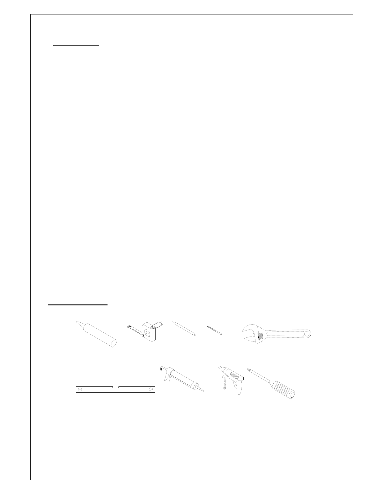
Tools Required
Tape
Caulk
Measure
Level
Rev. 1.2.
Pencil
Caulk
Gun
Drill bit
(D=3mm)
Electric
Drill
Wrench
Phillips
Screwdriver
3
Page 4
9
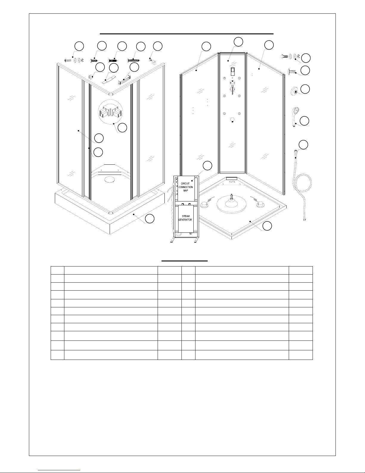
Detailed Diagram of Shower Cabin Component
10
14
6
7
15
11
8
16
12
13
2
17
1
3
22
21
20
19
18
5
4
Packing List
01 Control panel 1pc 12 Round head screw ST4.2×25 16pcs
02 Left stationary glass 1pc 13 Glass bracket 2pcs
03 Right stationary glass 1pc 14 Hand shower bracket 1pc
04 Roof 1pc 15 Glass shelf 1pc
05 Tray 1pc 16 Guardrail 1pc
06 Stationary glass 2pcs 17 Generator assembly 1pc
07 Glass door 2pcs 18 Shower hose 1pc
08 Connector 2pcs 19 Hand shower 1pc
09 Bolt M4×16 14pcs 20 Wheel assembly 8pcs
10 Round head screw ST4.2×10 4pcs 21 Bolt M5×8 8pcs
11 Round head screw ST4.2×16 14pcs 22 Bolt M6×25 (with washer) 2pcs
After you have checked that all components are there, you will be ready to start the
installation of your DreamLine shower cabin.
Rev. 1.2.
4
Page 5

Cabin Installation
1. Choose the location where you will be installing the tray, mark the location of the tray
because you may need to move it out from the position for better assembling
procedure. Check on the drain if it is fastened tight enough to make sure it won’t leak
after complete tray installation.
2. Also check all the hose connections to prevent leakage. Your plumber may want to
replace the drain flex hose to hard PVC pipes which is also possible (instructions are
provided in the manual).
3. For installation of the drain in the floor please refer to the Legs and frame position
(top view) diagram and fig1 (actual poison of the drain and frame on the tray).
4. Install the water outlet and power supply box. You need 1/2” minimum water supply
lines for hot and cold water with shout off valves. Power supply is required 20A
220V dedicated #12 3/1 wire line with GFCI breaker.
5. Place the Tray (5) in the required position. Adjust the legs to level the tray in case
the surface is uneven. Fasten the counter nuts on the legs to secure the height. See
Fig 2 for details.
NOTE: For steps 6, 7 and 8, it will be necessary to apply silicone sealant
between the panels and the panels and tray.
6. Move the Tray (5) out; put the Control panel (1) onto the tray; then secure them
with Round head screws ST4.2×25 (12). See Fig 3 for details.
7. Locate the Left stationary glass (2) onto the tray. Secure the left stationary glass
and the control panel with Bolt M4×16 (9). Secure the tray and the left stationary
glass with Round head screws ST4.2×25 (12). See Fig 4 for details.
8. Repeat Step 7 to install the Right stationary glass (3). Attach the Glass bracket
(13) to the left stationary glass and the Hand shower bracket (14) to right stationary
glass. See Fig 5 for details.
9. Locate the stationary glass panels from the package. Secure the Connectors (8)
and the guide r a i l of the Stationary glasses (6) with Round head screws ST4.2×10
(10). See Fig 6 for details.
10. Put two Wheel assemblies (20) into the groove of the upper guide rail; then lo cate
the Glass door (07) to the position. Secure it using Bolt M5×8 (21). See Fig 7 for
details.
11. Put the shower enclosure assembly onto the tray. Drill holes on the glass profiles of
the stationary glass; then secure them with Round head screws ST4.2×16 (11).
See Fig 8 and Fig 9 for details.
12. Apply the silicon sealant on the top aluminum profiles of the control panel (1), left
and right stationary panels (2,3) and stationary glass (6). Put the Roof (4) on the top
of the shower enclosure assembly. Secure the roof and the right and left stationary
glass with Round head screws ST4.2×25 (12). See Fig 10 and Fig 11 for details.
13. Install the Glass shelf (15) and the Guardrail (16) onto the left stationary glass. See
Fig 12 for details.
14. Place the Generator assembly (17) on the tray; then secure it to the tray with Bolt
M6×25 (with washer) (22). Connect the light, fan, speaker wire from the roof to the
generator. Connect the steam generator circuits; then connect it to the power supply.
See Fig 13 for details.
drain and steam line will be connected.
15. Connect the flexible hose to the shower head. Secure this item in place on the back
panel. Make sure all the water connections are water tight. Put the drain pipe into
the drain opening in the floor. Connect hot water to the red mark water inlet and cold
water to the blue mark water inlet.
DO NOT turn power supply on until the water supply, the
Rev. 1.2.
5
Page 6

16. Do not move the cabin into the place until you check all the components for any
leakage or problems; open each valve to see how it works, check thermostatic or
mixer valve for hot and cold water. You may need to tight some connections (during
storage and transportation connections may get loose). If you do not see any
leakage, then you can move it to the permanent position and finish your project. See
Fig 14 and Fig 15 for details.
17. Use the Phillips screwdriver #2 (do not use power screwdriver) to adjust the upper
wheels, make sure they move smoothly and the doors close tight. Connect the
flexible hose to the hand shower. Secure this item in place on the control panel. See
Fig 16 for details.
18. Seal with silicone on all connections between the vertical p rofiles and the back panel,
bottom rail and tray, tray and back panel. Let it dray for 24 hours before moving the
cabin. See Fig 17 for details.
19. Fig 19 shows the location of the handle. The upper figure is shown the outside of the
shower cabin and the bottom figure is shown the inside of the shower cabin.
945
477
240
224
44
477
945
224
240
44
Fig 1 Legs and frame position (top view)
Rev. 1.2.
6
Page 7

1
2
Fig 2 Fig 3
1
2
3
Rev. 1.2.
Fig 4 Fig 5
7
Page 8

1
1
4
2
2
¢3mm
3
Fig 6 Fig 7
5
6
¢3mm
3
1
2
Fig 8 Fig 9
Rev. 1.2.
8
Page 9

1
2
Fig 10 Fig 11
1
Rev. 1.2.
2
3
Fig 12 Fig 13
9
Page 10

Blue
1
3
Red
2
4
Cool
Hot
Fig 14 Fig 15
1
1
2
3
Rev. 1.2.
Fig 16 Fig 17
2
10
Page 11

a
1
2
Fig 18 Fig 19
Thermostatic Valve Using Controls
z Valv e “a” turns on water of the “tropical rain” head shower.
z Valve “b” turns on water of eight massage jets.
z Valve “c” turns on water of the hand shower. Turn the revolve cover of
the shower head will change water pattern.
z Thermostatic valve “d” adjusts water temperature on any valves you
are using.
b
OFF
d
1
3
1
1
2
2
1
F
c
0
0
5
9
Steam generator control
Temperature - Temperature +
Time setting
Function Illustration of the Control Board
Rev. 1.2.
Celsius
Ti me -
Steam
Temperature setting
Fahrenheit
Ti me +
Top light
Power
11
Page 12

Performance
z The control uses a blue color back light liquid crystal display with white back light
induction type touching key.
z Turning the steam on will fill the generator with water automatically, when system is
shut-down an automatic water draining system turn on.
z Includes steam and light and fan control functions.
z Steam temperature regulation range: Centigrade temperature 30~60C, Fahrenheit
86~140F; Steam time regulation range: 0~60 minutes.
z Automatic temperature controls also include tracking of excess temperature, over
pressure and power leakage protection function.
Operation Instructions:
Switch-on: Push the power switch, the present cabin temperature is shown on the
display, the top light turns on, and the system stays in the state of readiness.
Steam: Push the steam key directly to turn steam function on or off.
Temperature-set: Push temperature setting key, ambient temperature is shown on
the screen. Push the “temperature +” or “temperature –“key to get the wanted steam
temperature. The temperature will gradually increase or decrease within 30 ~ 60℃.
“Celsius” displays the Celsius temperature; “Fahrenheit” displays Fahrenheit
temperature. If the ambient temperature in the cabin is higher than that set by the
steam bath temperature, the steam generator can not be started.
Time-set: Push the time setting key and the steam generator and control go into the
time-set state; and push the “time +” or “time –“key to get desired time of the steam
bath. The time range is 5~60 minutes.
Lighting: Push the light key, and the light and the fan can be s w itched on or off.
Switch-off: Push the power key and switch off all the functions.
If not using steam options/control for a long time – we suggest that you switch off
the main electric power of the units
Warnings
Do not connect this steam shower with other electric appliances not recommended by
DreamLine™, and do not take ap art the hermetically sealed lines or the electric lines
from the power box.
A drainage pipeline shall be fixed to auto-drain valve of the main steam generator,
and it’s better to add a water filter before the water entr ance to increase generator’s
service life.
The steam generator should be working with water hardness levels 60-120 mg/l. If
hardness of your water more than recommended it can cause “scale” (mineral build
up in pipes and plumbing fixtures). Scale can cause of your steam unit damage. You
need to treat your water. Water soft eners are the most frequently used of all waterconditioning devices and are installed for reducing hardness for private wells and
utility supply with high levels of calcium or magnesium.
The line from the power box shall be plugged according to the digit capacity and the
size. Do not short circuit.
The steam generator is complicated option and shall be installed by the qualified and
authorized technical persons.
DreamLine™ shall not be responsible for negative consequences due to any
incorrect installation or improper operations per instructions listed above.
Rev. 1.2.
12
Page 13

Product Maintenance
1. Tempered glass can be clean with nonabrasive bathroom cleaner or any glass
cleaner you use elsewhere in your home. Rinse off any glass cleaner that gets on the
aluminum as soon as possible to avoid damage to the anodized surface. Avoid striking
it with any sharp or hard objects. Such damage can cause either immediate or delayed
breakage of tempered glass.
2. The aluminum in your shower door is durable and resistant to water damage. It is
advisable, but not necessary to wipe it with your towel after your shower. Clean it as
often as needed to keep the buildup off. Never use any type of abrasive cleaner. Use
only a soft damp cloth and nonabrasive b athroom cleaners.
Rev. 1.2.
13
 Loading...