

Page 1
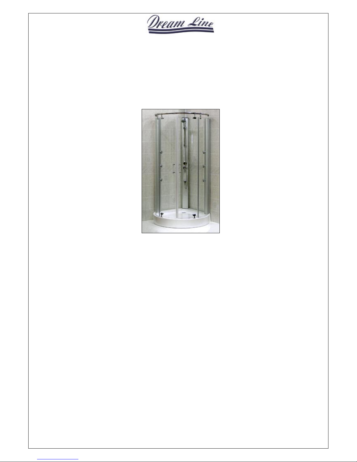
Murano / DLG-36
Shower Enclosure User’s Guide
I. Mounting Preparation
1. After opening the case, read this introduction carefully, check all the packed parts, examine the shower cabinet
for shipping damage. If the unit has been damaged or has a finishing defect, please contact your local
distributor within 2 business days. Please note that DreamLine Guarantee will not cover shipping damage or
such finishing defects once the unit has been installed. Your distributor’s responsibility for damage in transit
is limited after the shower package has been transferred to the transportation company, so you may have to
contact the transportation company directly to report damage. Contact your distributor or DreamLine if you
have any questions.
2. You shou ld make sure that the floor is leveled and solid and will be ab le to support the total weight of the unit
and its occupant. You should also consult your local building codes on any questions on installation
compliance with standards.
3. Install all of the required plumbing and drainage before securing the shower. Use a competent and licensed
(if required by local code) plumber for all plumbing installation.
4. Please insure that prior to the installation the floor is leveled and the walls are at right angles. While some
adjustment in leveling of the tray is possible, irregular floor level or improper angle of side walls will result
in serious problems for your installation.
5. Necessary Tools: Conventional woodworking tools, Screwdriver, Silicone sealant, Electric drill, Regular drill
bits (1/8”, 7/64”), Phillips screwdriver, Level, Measuring tape, Pencil and Stepladder. Bear in mind that you
will need at least two people to assemble the unit.
Page 2
II. Packing List
Plastic Dowel
12pcs
Glass entry door pivots 4sets
Tapping Screw ST4.2*30
20pcs
Rotation pedestal 2sets
Wall Connecting Profile
2pcs
Support bar door bracket 2sets
Doorframe, Panel Profile, Plastic Strip
2sets
Pipe covering 2sets
Side glass panel with plastic strip
2pcs
Connecting screw M4X15 4pc
Entry door glass with plastic strip
2pcs
Handle 2sets
Stainless steel top support bar
1pc
Tray 1pc
Glass clip
2sets
J11-1900 Massager 1set
Dia. 1
Dia. 2 Dia. 3
16
9
6
14
4
Page 3

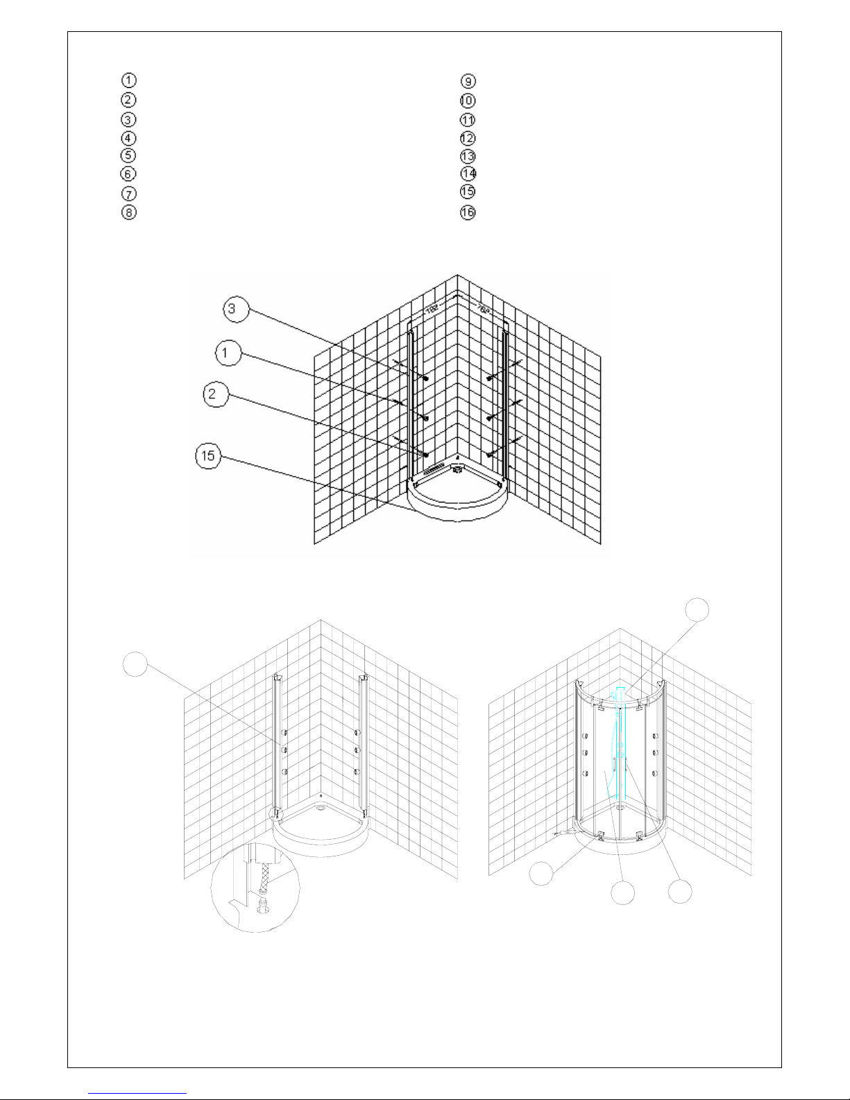
PARTS
III. Mounting Process:
1. Put the tray in the designated position and level it using water level. (Step1)
NOTE: If the tray is not correctly leveled doors may not operate as required.
2. Apply caulking silicone to boarders of the tray and then to the edges to protect the unit from leaking.
Make sure all the seals are filled up. Push the tray all the way down into the corner and remove the
excess caulking using a soft cloth. Allow the caulk to dry before proceeding the shower enclosure
assembly. (Step2)
3. Put apart the middle column assembly with the showerhead. (Step3, Step4)
4. Fasten the back part of the middle column assembly to the wall using 4 self-tapping screws #3 and
dowels #7. (Step6)
5. Tighten up the water pipe connector using the part #8 (Step7), plug the water hose into the water pipe
connector and tighten it up using part #9. (Step8)
6. Plug the hot and cold water hoses to the water supply. (Step9)
7. Place the front part of the middle column back and fasten the assembly with the 4 original bolts #5.
(Step10)
8. Locate the wall connecting profiles, level them and mark the holes on the wall according to the holes on
the wall profiles. (Step11)
9. After drilling, insert plastic dowels (part #7) and apply caulking silicone to the back part of the profile
and then fasten the wall connecting profiles to the wall using (quantity) screws. (Step12)
10. To connect the water pipes from the side jet columns repeat Steps 7 and 8. Place the front cover parts
(Step13) and screw them tight. Keep in mind that you should not push the front parts of the columns by
the jets to prevent them from damaging. Make sure the jet columns are leveled (Step14).
11. Attach waterproof plastic strips to the side glass panels (Step15) and insert them into the side jetted
columns (Step16).
12. When the side glass panels are in the place (Step17), insert the metal brackets into the support bar in a
following order: see Step18.
13. Then insert the support bar into the slots of the side jet columns and fasten it (Step20).
14. Secure the side glass panel to the metal bracket using the parts #1, 2, 4, 10 and 11. (Step21)
15. Secure the bottom glass door pivot brackets to the entry door using the same parts #1, 2, 4, 10 and 11.
The bottom of the entry door is determined by the position of the holes for the brackets (Step22). Insert
the bottom pivots into the slots, th en insert the top pi vots int o the slots a nd then secure th e brack et to the
entry door making sure you place the plastic gaskets in between the glass and metal nuts (Step23).
16. Secure the brackets to the support bar to prevent them from sliding back and forth using part #6
(Step24).
17. Attach handles, making sure there are plastic gaskets in between the glass (Step 25).
18. Attach the bottom waterproof plastic strip to the bottom of the doors (Step 26).
Page 4

IV. Sealing:
Apply clear silicone water sealant around the outside perimeter of any fixed shower
components (horizontally between bottom of any fixed side glass panels and tray, as well
as vertically between the wall, wall profiles and any side glass panels). Do not apply
silicone on the inside of the shower – this will cause your shower unit to leak.
NOTE: Allow 24 hours for the silicone to set before testing or using the shower.
NOTE: Improper application of silicone sealant may cause your shower to leak.
Step 1
Step 2
Step 3
Step 4
Step 5
Step 6
Step 7
Step 8 Step 9
Page 5

Step 10
Step 11
Step 12
Step 13
Step 14
Step 15
Step 16
Step 17
Step 18
Step 19
Step 20
Step 21
Page 6

Step 22 Step 23
Step 24
Step 25
Step 26
Page 7

DreamLine
Shower Enclosure, Jetted Shower and Shower Columns
Limited Warranty
CONSUMER RESPONSIBILITIES
Your DreamLine Shower Products will remain beautiful for many ye ars if you take car e of them. Some of the waterproofing plast ic
strips and other seals will need to be replaced when they show signs of wear, yellowing, or are not watertight. Refer to the parts list
of your manual for all seals. Water conditions in various parts of the countr y will determine any extra cleaning attention you may
have to give your new shower enclosure or jetted shower. DreamLine does not recommend the use of harsh abrasive cleansers on
any of its products. Harsh cleansers will damage the metal or glass finish on your shower enclosure or jetted shower.
REQUESTING SERVICE
Here’s what you need to do if you require service:
1. Contact the dealer or contractor who sold and installed the product. They should be able to solve any problems you may have.
2. If your dealer or contractor cannot solve the problem, they will contact or supply yo u with the name of the local DreamLine
Distributor or a DreamLine Direct Technical Specialist
3. If you are unable to obtain warranty service through either your contractor or DreamLine distributor, please write us directly at
4. Include all pertinent information regarding your claim, including a com plete description of the product, model numbers, colors,
finishes, and the date the product was installed. Include a description of the problem, and a photocopy of your invoice and
purchase receipt(s) for the products involved. Also please provide information the name and contact telephone numbers of the
contractor and distributor.
Please note that under any circumstances, DreamLine products should not be returned to your dealer, distributor or directly to
DreamLine without a written Return Merchandise Authorization (RMA).
LIMITED ONE-YEAR WARRANTY
This warrantee extends only to the original owner/end-user for personal household use only. For commercial uses, additional
limitations may apply.
DreamLine warrants acrylic surface against blistering or cracking and chipping res ulting from defect in the acrylic surface material
when used under normal condition and service for a period of one (1) year from the purchase date.
DreamLine warrants mirrors, shower doors, shower massage systems, faucet finishes and fittings to be free from defects in
workmanship and materials under normal use and service for a period of one (1) year.
DreamLine further warrants the structure of the acrylic shell against loss of water through the fiberglass laminate of the acrylic body
as a result of defect in materials and workmanship for a period of five (5) years from the purchase date.
DreamLine will, at its election, repair, replace, or make appropriate a djustment where DreamLine optional ins pection discloses any
such defects occurring in normal usage within the warrantee periods. Please note that DreamLine is not responsible for
installation or removal costs.
Improper modification of any enclosure, jetted shower or shower column components m ay void the warranty - so please install the
product as directed in the manual. This warranty does not cover any claim arising from abuse, misuse, negligence, accident,
improper installation or operations on the part of the purchaser. This warranty is void if the DreamLine product is subject to
alterations, or if repairs are attempted by anyone other than an authorized agent of DreamLi ne. This warranty does not extend to
any plumbing or components installed by dealers, installers or by any party other than DreamLine.
Implied warranties, including that of merchantability or fitness for a particular purpose, are expressly limited in duration to
the duration of this warranty. DreamLine disclaims any liability for special, incidental, or consequential damages.
Some states do not allow limitations on how long an implied warranty lasts or the exclusion or limitation of speci al, incidental, or
consequential damages, so these limitations and exclusions may not apply to you. This warranty giv es you specific legal rights. You
may also have other rights which vary from state to state. This limited warranty provides specific legal rights as they apply within
the USA, and other rights may be available, but may vary from country to country.
This is our exclusive written warranty for DreamLine Enclosure, Jetted Shower and shower Column Purchases made after
May 2004. DreamLine reserves the right to modify this warranty at any time, and the consumer understands that such
modification will not alter the warranty conditions applicable at the time of the sale of the product.
DreamLine
2840 Pine Road, Bld D
Huntingdon Valley, PA 19006
ATTN: Customer Service Department,
 Loading...