

Page 1
1
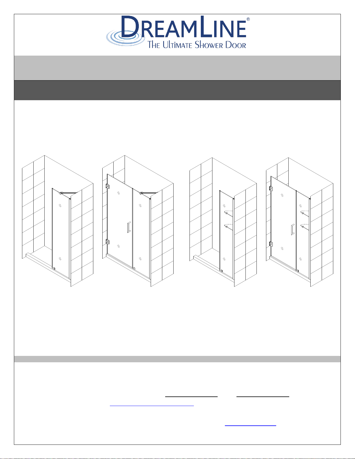
UNIDOOR (STYLE B & C)
SHOWER DOOR GLASS PANEL INSTALLATION INSTRUCTIONS
Style B Style C
IMPORTANT
DreamLine® reserves the right to alter, modify or redesign products at any time without prior notice.
For the latest up-to-date technical drawings, manuals, warranty information or additional details
please refer to your model’s web page on DreamLine.com
Please read these instructions carefully before installing. If you have any questions regarding
installation, please contact our technical support specialists Monday through Friday 8AM –
7PM and Saturday 9AM-5PM EST at Phone: 1-866-731-2244, Fax: 1-866-857-3638 or e-mail our
technical support group at [email protected]
For more information about DreamLine® products please visit DreamLine.com
UNIDOOR (STYLE B & C) Ver 2 Rev 10 09/2016
Page 2

2
Model#s:
SHDR-20297210
SHDR-20307210
SHDR-20317210
SHDR-20327210
SHDR-20337210
SHDR-20347210
SHDR-20357210
SHDR-20367210
Model#s:
SHDR-20417210C
SHDR-20427210C
SHDR-20437210
SHDR-20447210
SHDR-20457210
SHDR-20467210
SHDR-20477210
SHDR-20487210
SHDR-20477210C
SHDR-20487210C
SHDR-20497210
SHDR-20507210
SHDR-20517210
SHDR-20527210
SHDR-20537210
SHDR-20547210
SHDR-20537210C
SHDR-20547210C
SHDR-20557210
SHDR-20567210
SHDR-20577210
SHDR-20587210
SHDR-20597210
SHDR-20607210
Model#s:
SHDR-20357210CS
SHDR-20367210CS
SHDR-20377210S
SHDR-20387210S
SHDR-20397210S
SHDR-20407210S
SHDR-20417210S
SHDR-20427210S
SHDR-20417210CS
SHDR-20427210CS
SHDR-20437210S
SHDR-20447210S
SHDR-20457210S
SHDR-20467210S
SHDR-20477210S
SHDR-20487210S
SHDR-20477210CS
SHDR-20487210CS
SHDR-20497210S
SHDR-20507210S
SHDR-20517210S
SHDR-20527210S
SHDR-20537210S
SHDR-20547210S
SHDR-20537210CS
SHDR-20547210CS
SHDR-20557210S
SHDR-20567210S
SHDR-20577210S
SHDR-20587210S
SHDR-20597210S
SHDR-20607210S
Finishes: -01 Chrome -04 Brushed Nickel -06 Oil Rubbed Bronze -09 Satin Black
UNIDOOR (STYLE B & C) Ver 2 Rev 10 09/2016
Page 3

3
Preparation
1. Prior to installation, examine all boxes and packages for shipping damage and compare the piece
count with your packing slip. After opening all boxes and packages read this introduction carefully.
Check that all of the needed parts are included in the package by checking off the components on
the “Detailed Diagram of Shower Door Components”. If the unit has been damaged, has a
finishing defect, or has missing parts, please contact our customer support department within
3 business days of the delivery date. Please note that DreamLine® will not replace any
damaged products or missing parts free of charge after 3 business days or if the product has
been installed. Feel free to contact DreamLine® if you have any questions, and please provide an
order number, job name or other proof of purchase to help us identify your original order.
2. Please note that you should consult your local building codes with questions on installation
compliance standards. Building and plumbing codes may vary by location, and DreamLine is
not responsible for code compliance standards for your project and will not accept any
returns.
3. If this unit is going to be installed in new construction, please, install all of the required plumbing
and drainage before installing the shower. Use a competent and licensed (if required by local
code) plumber for all plumbing installation
4. Prior to the installation, please ensure that the installation surface is level and solid and will be
able to support the total weight of the unit. Also make sure that the walls are plumb. Depending
on the type of unit you are installing, some adjustments in leveling may be possible. However,
irregular installation, surface level or out of square conditions can result in serious problems for
your installation. Please note that some adjustments and drilling may be necessary. Please protect
all primary surfaces of the product during installation. Never set your glass down directly onto a
tile floor. Always use a piece of wood or cardboard to protect the bottom edge and corners of
the glass.
5. Note: The installation of this unit requires that you drill down into the threshold.
6. This unit must be installed upon a finished threshold and against finished walls.
7. This model requires a minimum 5/8” of flat threshold space for installation.
8. Professional installation recommended.
UNIDOOR (STYLE B & C) Ver 2 Rev 10 09/2016
Page 4
4
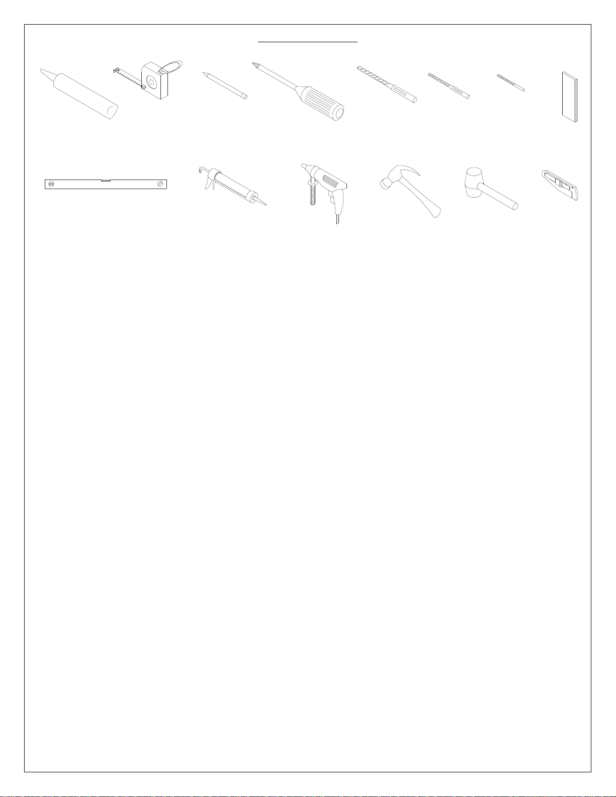
Tools Required
Caulk
Tape
Measure
Pencil
Screwdriver
Phillips
Drill bit
Level
Gun
Caulk
Drill
Electric
Hammer
Drill bit
(Ø=5/16")
(Ø=1/8")
Mallet
Knife
Wood
Drill bit
(Ø=1/4")
UNIDOOR (STYLE B & C) Ver 2 Rev 10 09/2016
Page 5
5
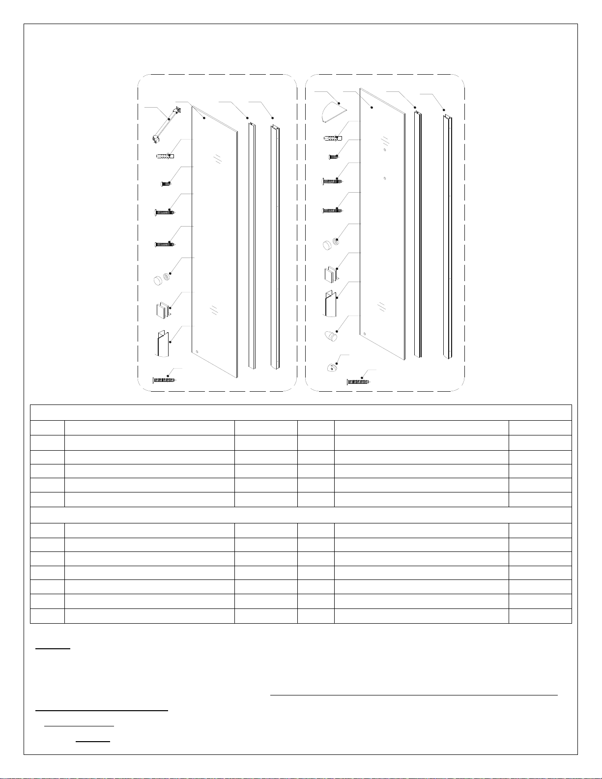
Detailed Diagrams of Shower Door Components
910
11
13
14
15
16
17
18
19
9
101112
13
14
15
16
17
18
19
23
22
21
Diagram A
Diagram B
23
12
Diagram A
09
Wall profile
1pc
15
Big flat head screw ST4.2×40
4pcs
10
Glass profile
1pc
16
Round head screw ST4.2×35
1pc
11
Stationary glass
1pc
17
Decorative screw cover
4pcs
12
Support bar *
1pc
18
Bottom bracket
1pc
13
Wall Anchor *
4pcs+1pc
19
Anti-Water strip (inline panel)
1pc
14
Round head screw ST4.2×10
3pcs
23
Countersunk screw ST4.2×40 *
1pc
Diagram B
09
Wall profile
1pc
16
Round head screw ST4.2×35
1pc
10
Glass profile
1pc
17
Decorative screw cover
4pcs
11
Stationary glass
1pc
18
Bottom bracket
1pc
12
Glass shelf
2pcs
19
Anti-Water strip (inline panel)
1pc
13
Wall anchor
8pcs
21
Shelf bracket (with nut)
2pcs
14
Round head screw ST4.2×10
3pcs
22
Shelf bracket (without nut)
4pcs
15
Big flat head screw ST4.2×40
4pcs
23
Countersunk screw ST4.2×40
4pcs
NOTE: Unpack your unit carefully and inspect it. Lay it out and identify all parts using the detailed
diagram and packing list in your manual as a reference. Before discarding the carton, check for small
hardware bags that may have fallen to the bottom of the box. If any parts are damaged or missing,
please contact DreamLineTM for replacement. The shipping boxes may contain extra parts not used in
your model configuration.
* ATTENTION: All parts that are marked with the star (*) not provided with 6” Stationary
panel. NOTE: Retain these installation instructions for future reference.
UNIDOOR (STYLE B & C) Ver 2 Rev 10 09/2016
Page 6
6
Value
inside
outside
outside
inside
Door
2
1
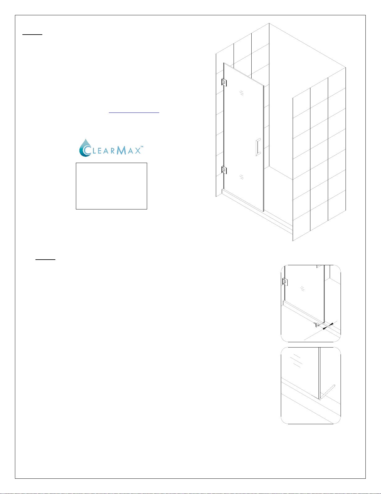
Fig. 1
The glass surface
with the ClearMax™
label must be
installed to face
inside of the shower
NOTE: The Unidoor shower door needs to be
installed prior to proceeding with the following
Stationary Glass installation instructions. Please
see the Single Shower Door installation manual
included in the door packaging for complete
shower door installation instructions. Before you
begin the installation, please recheck your shower
opening size. Specific size information can be
found on our website at DreamLine.com
NOTE: The Unidoor hinge is factory set to over close 8°.
The following procedure is recommended to ensure
proper alignment of the panel glass and door glass.
1. Align the Door so that it is perpendicular to the wall and
parallel to the threshold. Measure across the bottom span of
the Door and threshold on the outside of shower and
determine an equal value.
Mark a line on the threshold base on the handle side
See Fig. 1 for details.
UNIDOOR (STYLE B & C) Ver 2 Rev 10 09/2016
Page 7
7
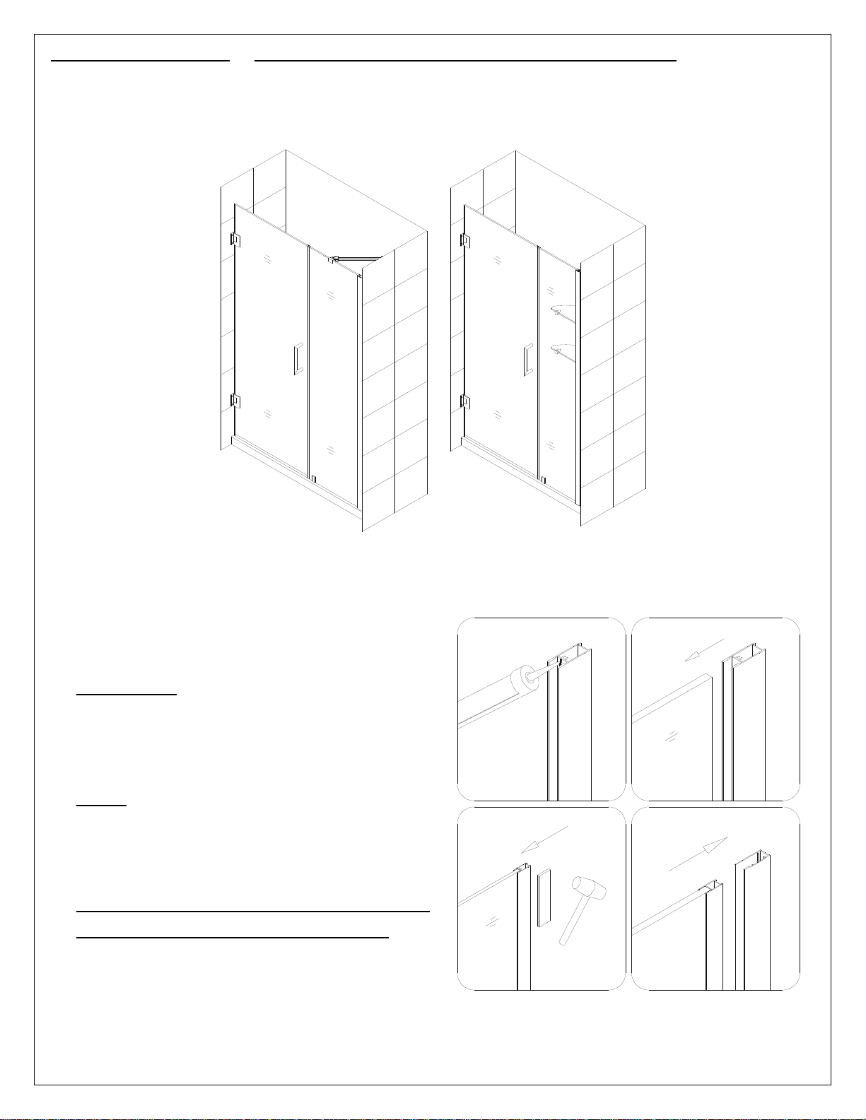
Style “B” and “C”: Stationary Glass Assembly and Installation
Style B
Style C
Fig. 2
1
4
3
2
NOTE: Use parts from Diagram “A” or “B” (depending on your model style) for the
Stationary Glass assembly and installation.
2. Apply clear silicone along the inner channel of
the Glass profile (10) and insert the
Stationary glass (11) into the channel.
ATTENTION: Please note that the bottom
hole in the corner of the Stationary glass
should be away from the Glass profile not
next to it.
NOTE: If you have difficulty sliding the
Glass profile over the Stationary glass, you
can slightly tap on the Glass profile with a
rubber mallet and a piece of wood.
NEVER use a metal hammer or hit the
profile without the wood bumper.
Insert the Stationary glass with attached
Glass profile into the Wall profile (09).
See Fig. 2 for details.
UNIDOOR (STYLE B & C) Ver 2 Rev 10 09/2016
Page 8
8
2
inside
outside
inside
outside
inside
inside
inside
outside
Fig. 3
Fig. 4
1
4 3 2
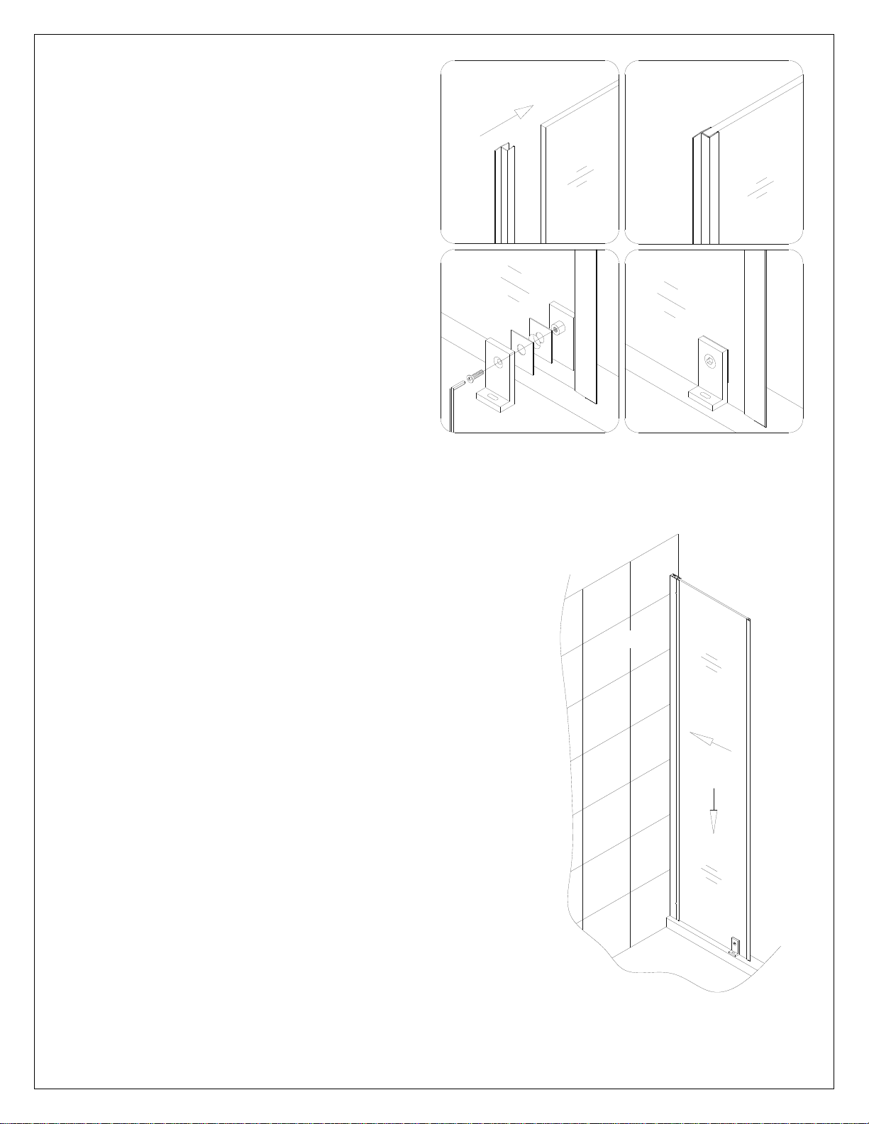
3. Press the Anti-Water strip (inline panel)
(19) onto the vertical edge of the Stationary
glass (11).
Attach the Bottom Bracket (18) through
the bottom hole of the Stationary glass.
See Fig. 3 for details.
4. Carefully butt the Stationary glass (11) up against the wall
vertically.
See Fig. 4 for details.
UNIDOOR (STYLE B & C) Ver 2 Rev 10 09/2016
Page 9
9
Ø5/16”
outside
inside
outside
inside
inside
inside
Door
Align stationary glass
and glass door
inside
1/16"-1/8"
Stationary
glass
Fig. 5
inside
inside
Fig. 6
4
3 2 1
Ø5/16”
5
4
3 2 1
5
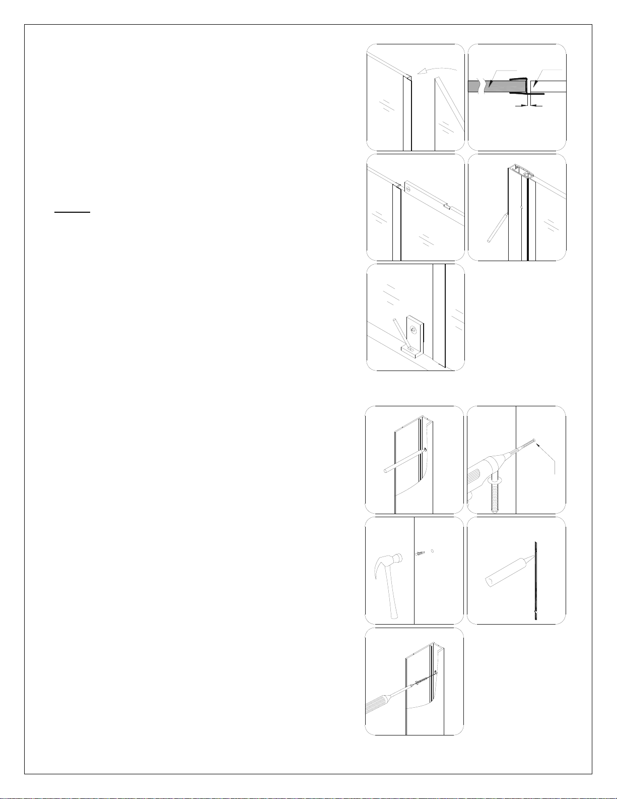
5. While securely holding the Stationary glass (11) close
the Glass Door and align the Stationary glass to it.
Use the door mark that was made in step #1 on the
threshold as a reference to ensure that the Door is
perpendicular to the wall.
If needed, adjust the position of the Stationary glass
so that the Anti-Water strip (inline panel) (19)
makes tight contact to the Glass Door from top to
bottom.
NOTE: The top of the Stationary glass must be
leveled with the Glass door.
Draw a line along the inner edge of the Wall profile
(09) on the wall.
Mark the drilling hole of the Bottom bracket (18) on
the shower base or threshold through the oval
notched hole.
See Fig. 5 for details.
6. Detach the Wall profile (09) from the Stationary
glass (11) and Glass profile (10) assembly.
Replace the Wall profile to the outlined position that
was made in step #5 and mark the drill holes on the
wall through the predrilled holes in the Wall profile.
Now drill holes in the wall using Ø 5/16” drill bit and
insert the Wall anchors (13).
Apply silicone along the Wall profile and around the
holes. Fasten the Wall profile to the wall with the Big
flat head Screw ST4.2×40 (15).
See Fig. 6 for details.
UNIDOOR (STYLE B & C) Ver 2 Rev 10 09/2016
Page 10
10
inside
inside
Ø 1/8"
outside
inside
inside
outside
Fig. 7
4
3 2 1
5
inside
outside
Fig. 8
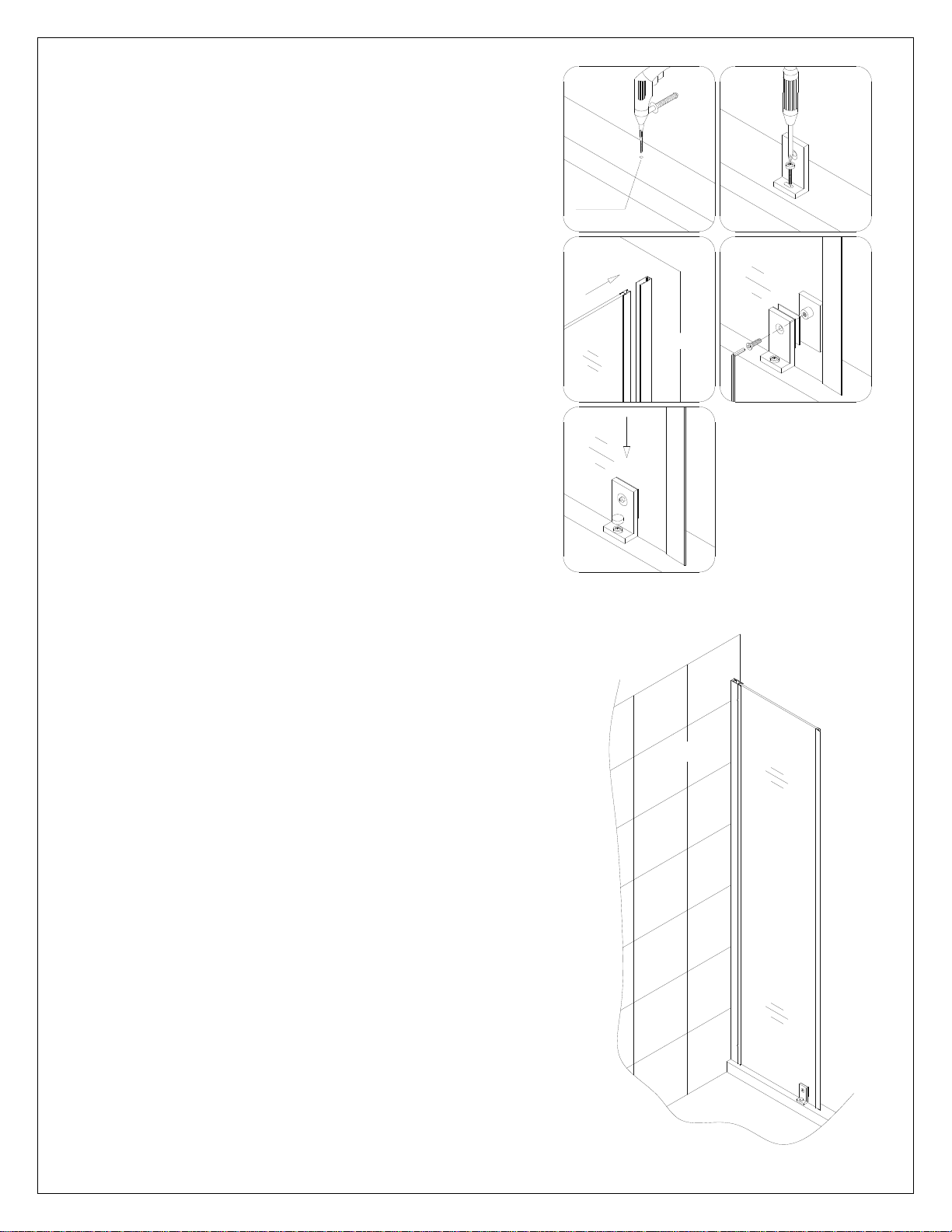
7. Drill the hole into the shower base or threshold for the
Bottom bracket (18) using Ø 1/8” drill bit at the drill
mark that was made in step #5.
Use the Round head screw ST4.2x35 (16) along with
a raised white washer to attach the Bottom Bracket
to the shower base or threshold. Move the Stationary
Glass (11) back into position and insert the Glass
profile assembly into the Wall profile (09).
Secure the Bottom Bracket (18) to the Stationary
Glass.
Cover the Bottom Bracket screw head with
Decorative screw cover (17).
See Fig. 7 and Fig. 8 for details.
UNIDOOR (STYLE B & C) Ver 2 Rev 10 09/2016
Page 11
11
Style B
Style C
Fig. 10
Ø1/8”
2 3 1
Fig. 9
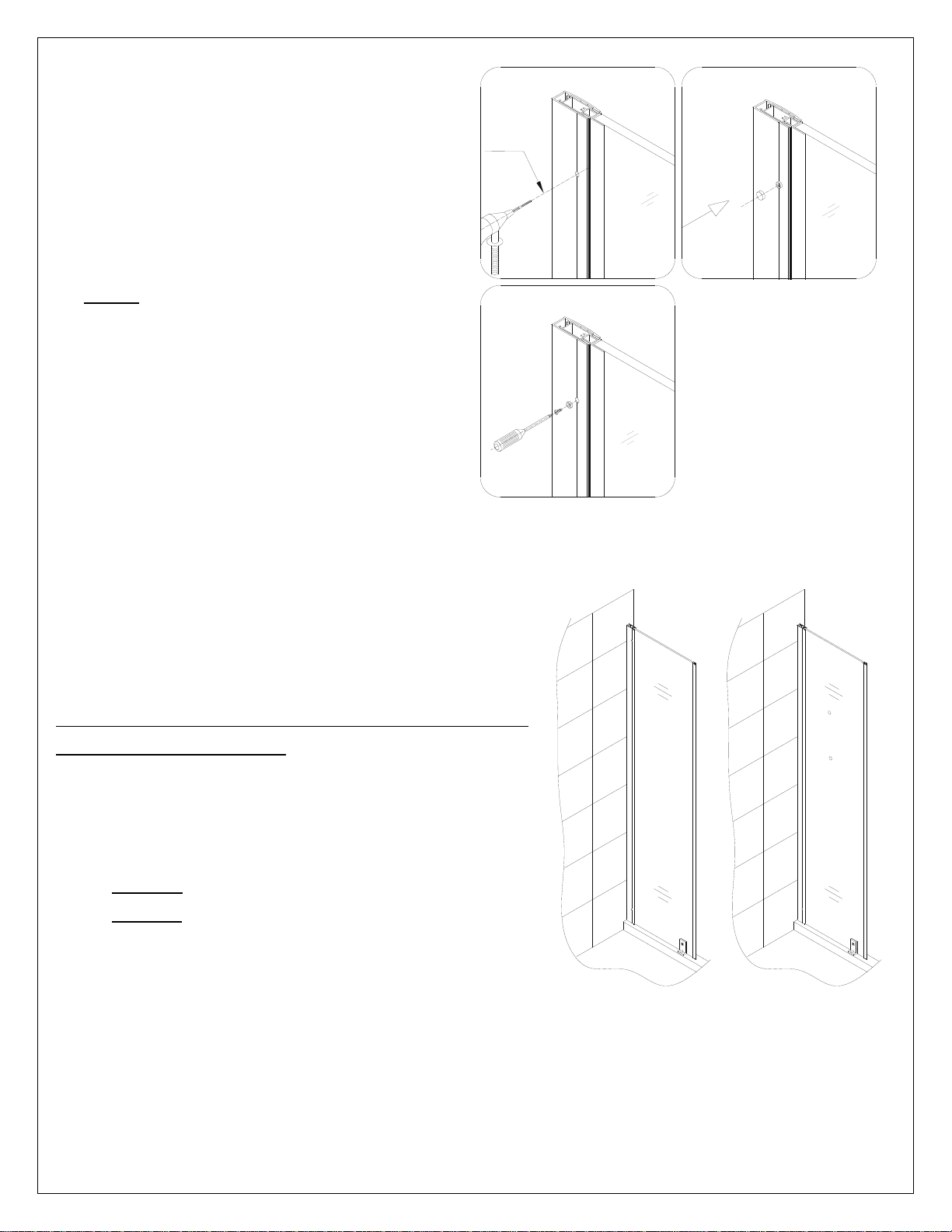
8. Recheck the alignment and spacing of the
Glass Door and Stationary glass (11) to
make sure the Door still opens and closes
correctly. After final adjustments of the
Stationary glass drill the holes in the Glass
profile (10) through the predrilled holes in
the Wall profile (09) using an Ø 1/8” drill
bit.
NOTE: You only need to drill through the
first layer of the Glass Profile.
Use Round head screws ST4.2×10 (14) to
attach the Wall profile to the Glass profile.
Cover the exposed screw heads with
Decorative screw cover (17).
See Fig. 9 and Fig. 10 for details.
9. Apply the sealant along the connection of the
Stationary glass to the wall and the Shower base or
threshold.
If the Stationary Panel width is 6”, the
installation is finished.
If the Stationary Glass width is 12” and over
you will need to continue your installation
from:
a) Style B for Support Bar installation.
b) Style C for Glass Shelves installation.
See Fig. 10 for details.
UNIDOOR (STYLE B & C) Ver 2 Rev 10 09/2016
Page 12
12
Style “B”: Support bar Assembly and Installation
5
3 2 4
1
6
Ø5/16”
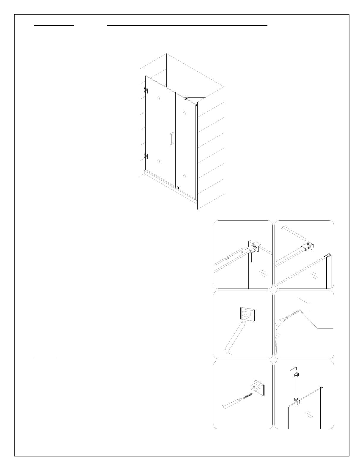
NOTE: Use parts from Diagram “A” for the Support Bar assembly and installation.
10. Locate the Support bar (12).
Adjust the bar to a proper position on the glass and
the wall. Level it horizontally. Hold it firmly and
outline the bracket’s position on the wall. Remove the
Support bar and detach the wall bracket from it.
Place the wall bracket against its outlined position on
the wall and mark the drilling hole.
Drill the hole using Ø 5/16” drill bit, insert the Wall
anchor (13) and fasten the wall bracket to the wall
with the Big flat head screws ST4.2×40 (15). Attach
the Support bar to the wall as shown on Fig 11.6 and
tighten the *set screws and the glass holding screw to
secure the glass.
*NOTE: Make sure that the rubber gasket is in
place on the glass on the side opposite of the set
screw before securing the Support bar.
See Fig. 11 for details
Fig. 11
UNIDOOR (STYLE B & C) Ver 2 Rev 10 09/2016
Page 13
13
Caulk
Fig. 12
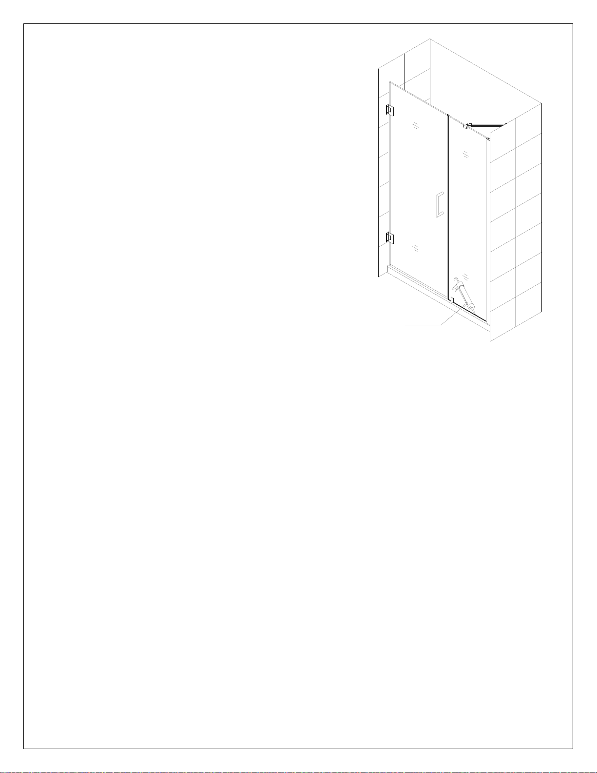
11. Apply a good quality mildew-resistant silicone along the
connection of the Stationary glass to the wall and the
Shower base or threshold. Allow 24 hours for the silicone
to fully cure before using the shower.
See Fig. 12 for details.
UNIDOOR (STYLE B & C) Ver 2 Rev 10 09/2016
Page 14
14
Style “C”: Glass Shelves* Assembly and Installation
6 4 5
2
3 1 6”
2”
Ø5/16”
Fig. 13
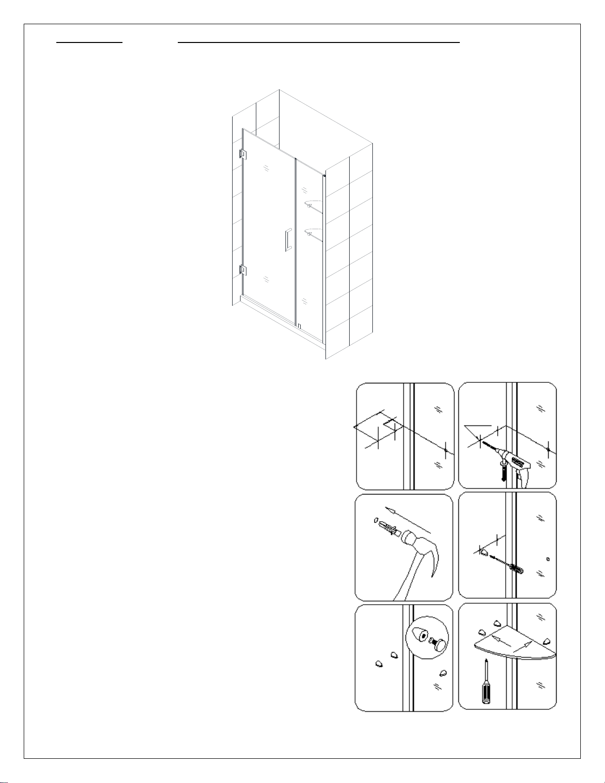
NOTE: Use parts from Diagram “B” for the Glass Shelves* assembly and installation.
12. Mark the Glass shelf* (12) position on the wall.
According to the measurements in Fig. 13.1, mark the
drilling holes for the Shelf brackets* (without nut)
(22).
Drill the holes using Ø 5/16” drill bit and insert the
Wall anchors* (13).
Attach the Shelf brackets* (without nut) to the wall
using the Countersunk screw* ST4.2×40 (23) and
attach the Shelf brackets* (with nut) (21) to the
Stationary glass (11).
Insert the Glass shelves* into the Shelf brackets*
and fasten the screws at the bottom of the brackets.
See Fig. 13 and Fig. 14 for details.
UNIDOOR (STYLE B & C) Ver 2 Rev 10 09/2016
Page 15
15
Caulk
Fig. 14
Fig. 15
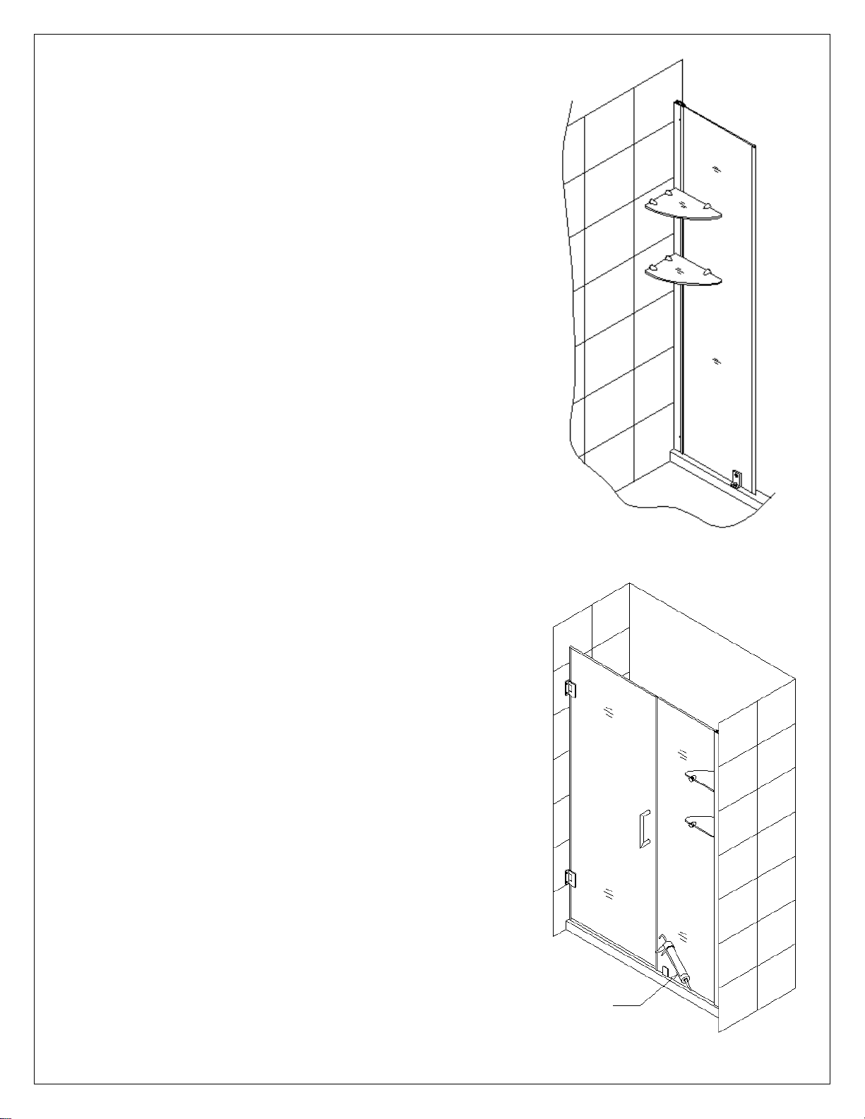
13. Apply a good quality mildew-resistant silicone along the
connection of the Stationary glass to the wall and the
Shower base or threshold. Allow 24 hours for the
silicone to fully cure before using the shower.
See Fig. 15 for details
UNIDOOR (STYLE B & C) Ver 2 Rev 10 09/2016
Page 16

16
Product Maintenance
BASES and BACKWALLS: To ensure long lasting life for your acrylic back walls: wipe them off
after each use with a soft cloth. To clean the acrylic back walls use non-abrasive sprays or cream
based cleaners. Avoid the use of aerosol spray cleaners. Never use abrasive cleansers, metal
brushes or scrapers that could scratch or dull the surface.
GLASS: To ensure long lasting life for your glass shower products: wipe them off after each use
with a soft cloth. Rinse and wipe off the glass using either a soft cloth or a squeegee to prevent
soap buildup and water spots (Hard water can etch the surface of the glass over time if left to dry).
To prevent scratching the surface: never use abrasive cleaners or cleaning products that contain
scouring agents. Never use bristle brushes or abrasive sponges that may scratch the surface.
HARDWARE: To ensure a long lasting finish: wipe off the metal parts after each use with a soft
cloth. Do not use abrasive cleaners or cleaning products containing ammonia, bleach or acid. If
accidentally used, rinse the surface as soon as possible to prevent damage to the finish (peeling or
corrosion). After cleaning the polished finishes, rinse thoroughly and wipe dry with soft cloth.
Clean stainless steel surfaces at least once a week. When applying stainless steel cleaner or polish
to stainless steel hardware, work with (not across) the grain. Never use an abrasive sponge or cloth,
steel wool or wired brush as these may permanently scratch the surfaces.
NOTE: To maximize the life of your door, it is important to regularly inspect the glass and
other hardware for misalignment, proper attachment, and/or damage. Contact DreamLine
with any questions or concerns.
UNIDOOR (STYLE B & C) Ver 2 Rev 10 09/2016
Page 17

17
TEL: 866-731-2244
FAX: 866-857-3638
DREAMLINE.COM
For more information on DreamLine® Shower Doors and Enclosures please visit DreamLine.com
UNIDOOR (STYLE B & C) Ver 2 Rev 10 09/2016
 Loading...