

Page 1
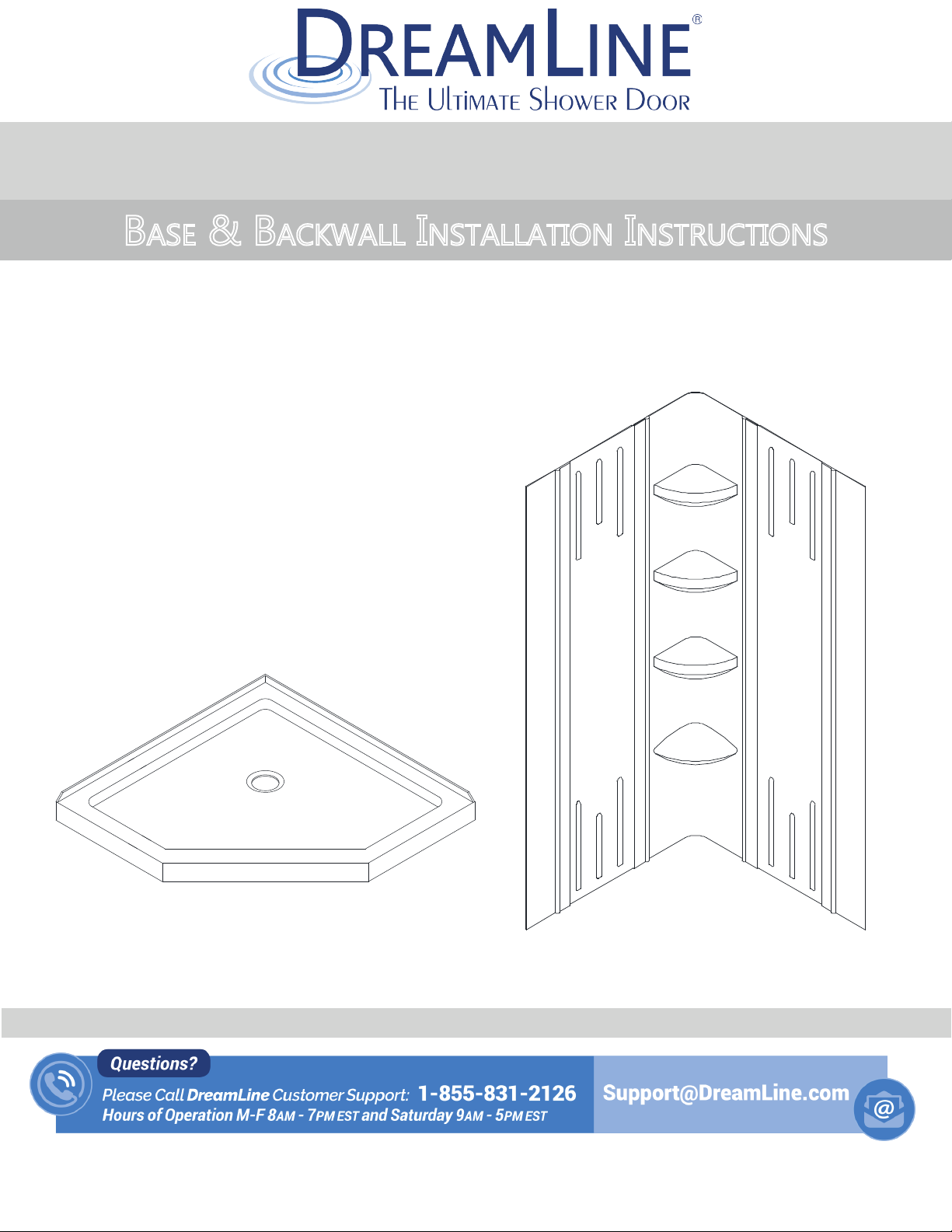
SlimLine Neo-Angle Base & Q-Wall-2
BASE & BACKWALL INSTALLATION INSTRUCTIONS
IMPORTANT
®
DreamLine
For the latest up-to-date technical drawings, manuals, warranty information or additional details please refer
to your model’s web page on DreamLine.com
reserves the right to alter, modify or redesign products at any time without prior notice.
STEP 1: Shower Base Installation Instructions
STEP 2: Shower Backwall Installation Instructions
For more information about DreamLine® Shower Doors, Tub Doors & Enclosures, please visit DreamLine.com
SLIMLINE NEO-ANGLE BASE & Q-WALL-2
©2017 DreamLine. All Rights Reserved
Page 2

©2018 DreamLine. All Rights Reserved
1
SLIMLINE SHOWER BASE
SHOWER BASE DIMENSIONS AND INSTALLATION INSTRUCTIONS
Please review this entire manual before beginning installation
Color options:
--- - White
-22- Biscuit
-88- Black
Double Threshold Shower Base with Corner Drain Configuration
shown as an example
IMPORTANT!
DreamLine® reserves the right to alter, modify or redesign products at any time without prior
notice. For the latest up-to-date technical drawings, manuals, warranty information or additional
details please refer to your model’s web page on DreamLine.com
For more information about DreamLine® products please visit DreamLine.com
SLIMLINE SHOWER BASE manual Ver 5 Rev 9 03/2018
Page 3
©2018 DreamLine. All Rights Reserved
2
XXX
Tape
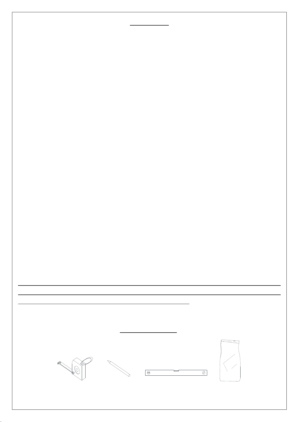
Measure
Pencil
Level
Mortar
Preparation
1. Prior to installation, examine all boxes and packages for shipping damage and compare the
piece count with your packing slip. After opening all boxes and packages read this introduction
carefully. Check that all of the needed parts are included in the package by checking off the
components on the “Detailed Diagram of Shower Door Components”. If the unit has been
damaged, has a finishing defect, or has missing parts, please contact our customer support
department within 3 business days of the delivery date. Please note that DreamLine® will not
replace any damaged products or missing parts free of charge after 3 business days or if
the product has been installed. Please contact DreamLine® if you have any questions and
please provide an order number, job name or other proof of purchase to help identify the
original order.
2. Install all of the required plumbing and drainage before installing the shower base. Use a
competent and licensed (if required by local code) plumber for all plumbing installation.
3. Shower bases must be installed by a licensed plumber. Please note that you should
consult your local building codes with questions on installation compliance standards.
Building and plumbing codes may vary by location and DreamLine® is not responsible for
code compliance standards for your project.
4. Make sure that prior to the installation the installation surface is leveled and solid and will be
able to support the total weight of the unit. Also make sure the walls are at right angles. While
some adjustment in leveling of the tray is possible, irregular installation surface level or
improper angle of side walls will result in serious problems for your installation. Please note
that some adjustments may be necessary during the installation process.
5. Center drain configurations are centered on the width only. See technical drawing tables
for drain locations.
6. Drain not included with this product. The drain
standard 2” compression fitted drain.
opening
is 3-3/8” in diameter and accepts a
IMPORTANT NOTE:
Dimensions provided are for reference only. Measure the actual shower tray
before installation. This includes overall dimensions and drain location.
Allowed tolerance for center of the drain is +/-1/2".
Tools Required
SLIMLINE SHOWER BASE manual Ver 5 Rev 9 03/2018
Page 4
©2018 DreamLine. All Rights Reserved
3
SLIMLINE SHOWER BASE manual Ver 5 Rev 9 03/2018
Page 5
©2018 DreamLine. All Rights Reserved
4
SLIMLINE SHOWER BASE manual Ver 5 Rev 9 03/2018
Page 6
©2018 DreamLine. All Rights Reserved
5
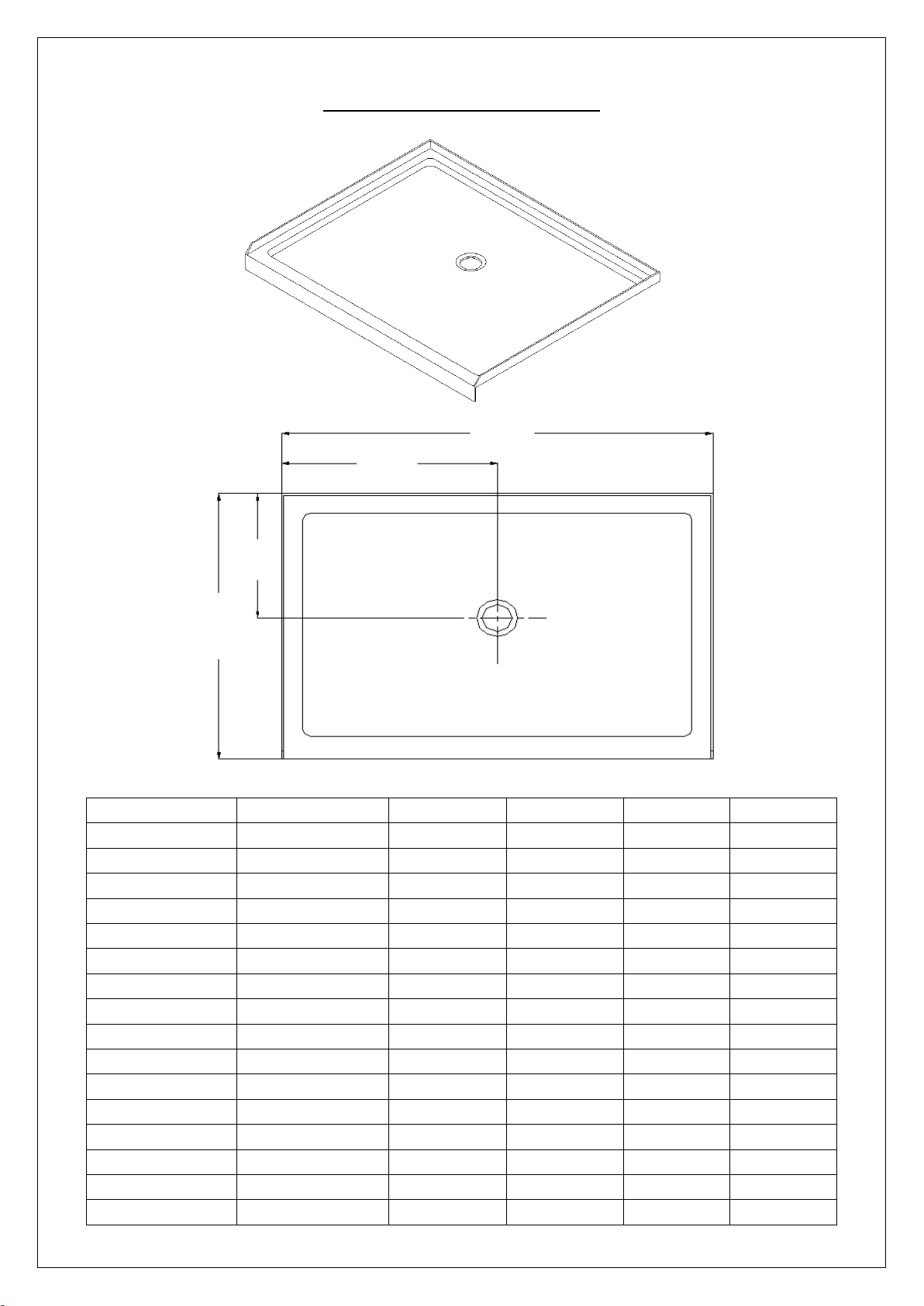
MODEL
SPECIFICATION
D (in)
W (in)
D1 (in)
W1 (in)
DLT-1132320
32"× 32"
32"
32"
15"
16"
DLT-1136360
36"× 36"
36"
36"
15"
18"
DLT-1132420
32” x 42”
32”
42”
15”
21”
DLT-1134420
34” x 42”
34”
42”
15”
21”
DLT-1136420
36” x 42”
36”
42”
15”
21”
DLT-1142420
42” x 42”
42”
42”
20”
21”
DLT-1132480
32"× 48"
32”
48”
15”
24”
DLT-1134480
34” x 48”
34”
48”
15”
24”
DLT-1136480
36"× 48"
36"
48"
15"
24"
DLT-1132540
32” x 54”
32”
54”
15”
27”
DLT-1134540
34” x 54”
34”
54”
15”
27”
DLT-1136540
36” x 54”
36”
54”
15”
27”
DLT-1130600
30"× 60"
30"
60"
15"
30"
DLT-1132600
32"× 60"
32"
60"
15"
30"
DLT-1134600
34"× 60"
34"
60"
15"
30"
DLT-1136600
36"× 60"
36"
60"
15"
30"
W
D
W1
D1
SINGLE THRESHOLD SHOWER BASE
Center Drain Configuration
SLIMLINE SHOWER BASE manual Ver 5 Rev 9 03/2018
Page 7
©2018 DreamLine. All Rights Reserved
6
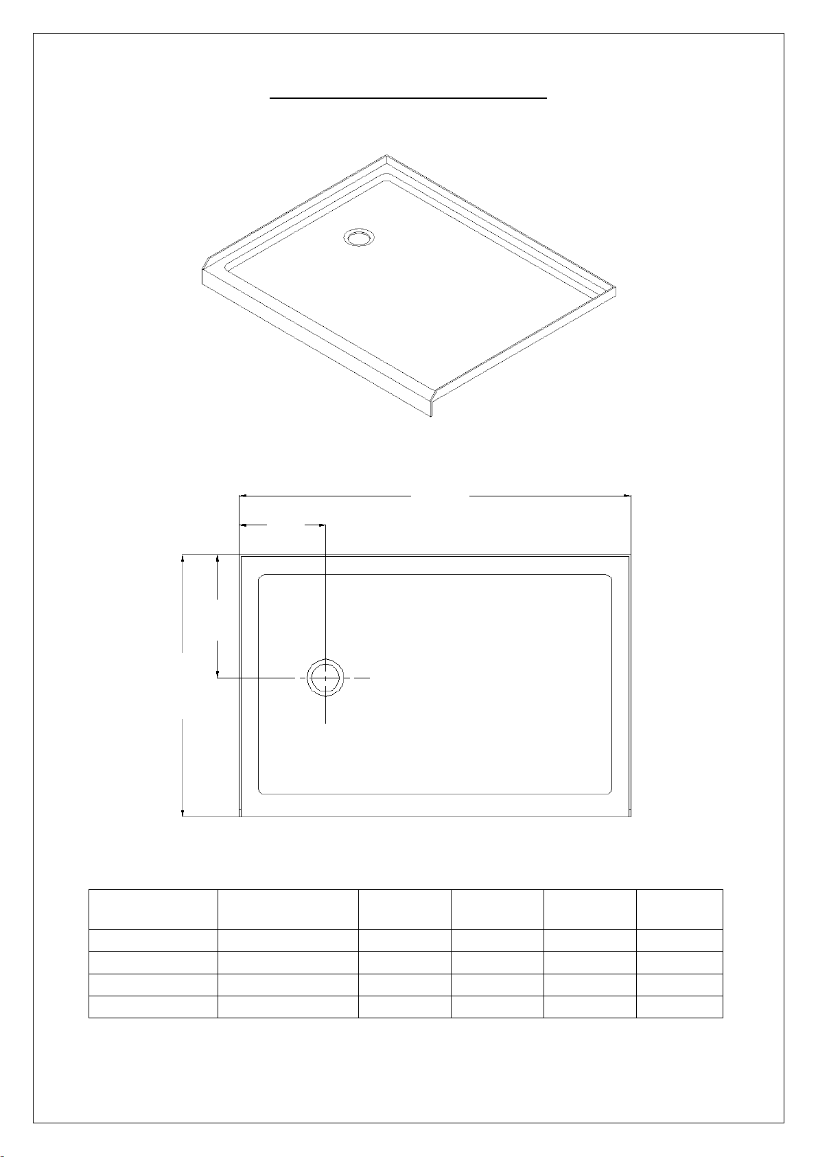
MODEL
SPECIFICATION
D (in)
W (in)
D1 (in)
W1 (in)
DLT-1130601
30"×60"
30"
60"
15"
12"
DLT-1132601
32"×60"
32"
60"
15"
12"
DLT-1134601
34"×60"
34"
60"
17"
12"
DLT-1136601
36"×60"
36"
60"
18"
12"
W
D
D1
W1
SINGLE THRESHOLD SHOWER BASE
Left-Hand Drain Configuration
SLIMLINE SHOWER BASE manual Ver 5 Rev 9 03/2018
Page 8
©2018 DreamLine. All Rights Reserved
7
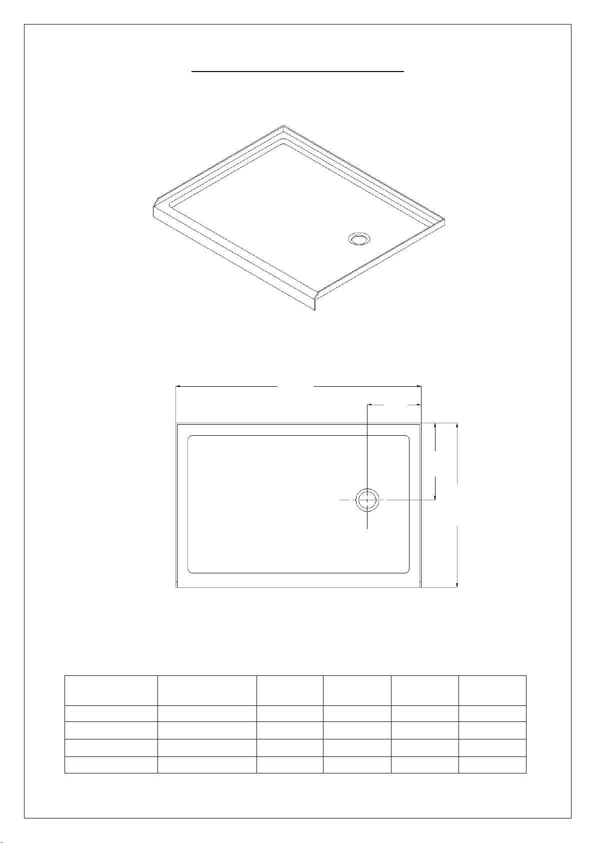
MODEL
SPECIFICATION
D (in)
W (in)
D1 (in)
W1 (in)
DLT-1130602
30"×60"
30"
60"
15"
12"
DLT-1132602
32"×60"
32"
60"
15"
12"
DLT-1134602
34"×60"
34"
60"
17"
12"
DLT-1136602
36"×60"
36"
60"
18"
12"
W1
W D D1
SINGLE THRESHOLD SHOWER BASE
Right-Hand Drain Configuration
SLIMLINE SHOWER BASE manual Ver 5 Rev 9 03/2018
Page 9
©2018 DreamLine. All Rights Reserved
8
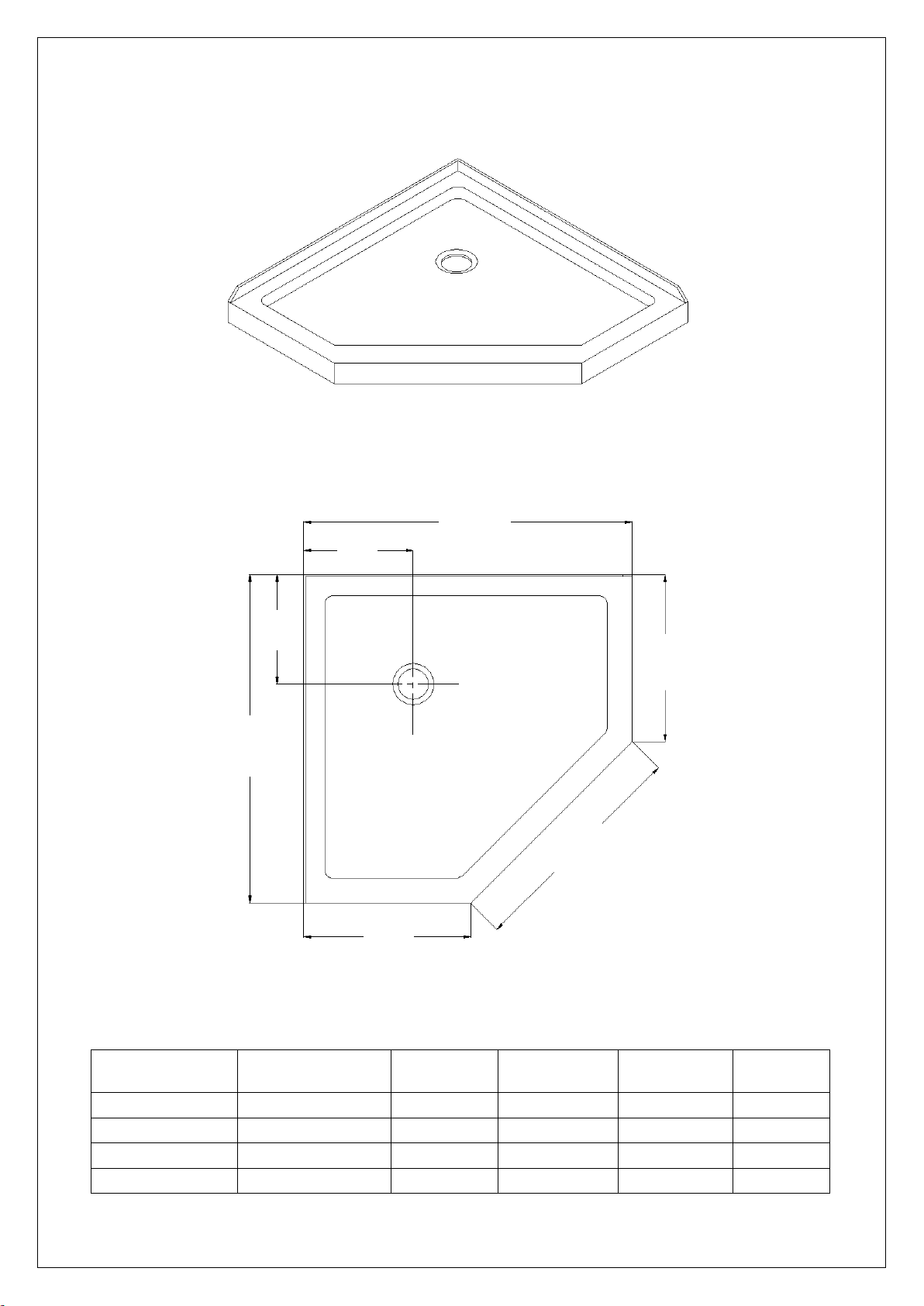
MODEL
SPECIFICATION
W (in)
A (in)
B (in)
C (in)
DLT-2036360
36"×36"
36"
18 5/16"
25"
12"
DLT-2038380
38"×38"
38"
20 5/16"
25"
12"
DLT-2040400
40"×40"
40"
22 5/16"
25"
14 3/8"
DLT-2042420
42"×42"
42"
24 5/16"
25"
14 3/8"
W
W
A A C C B
NEO ANGLE SHOWER BASE
SLIMLINE SHOWER BASE manual Ver 5 Rev 9 03/2018
Page 10

©2018 DreamLine. All Rights Reserved
9
MODEL
SPECIFICATION
W (in)
C (in)
R (in)
DLT-7033330
33"×33"
33"
12"
21 5/8"
DLT-7036360
36"×36"
36"
12"
21 5/8"
DLT-7038380
38"×38"
38"
12"
21 5/8"
W
W
C C R
QUARTER ROUND SHOWER BASE
SLIMLINE SHOWER BASE manual Ver 5 Rev 9 03/2018
Page 11
©2018 DreamLine. All Rights Reserved
10
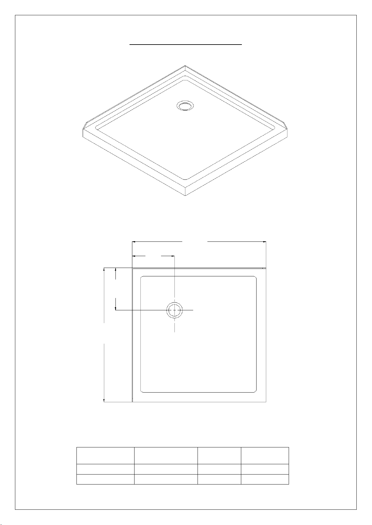
MODEL
SPECIFICATION
W (in)
C (in)
DLT-1032320
32"×32"
32"
12"
DLT-1036360
36"×36"
36"
12"
W
W C C
DOUBLE THRESHOLD SHOWER BASE
Corner Drain Configuration
SLIMLINE SHOWER BASE manual Ver 5 Rev 9 03/2018
Page 12
©2018 DreamLine. All Rights Reserved
11
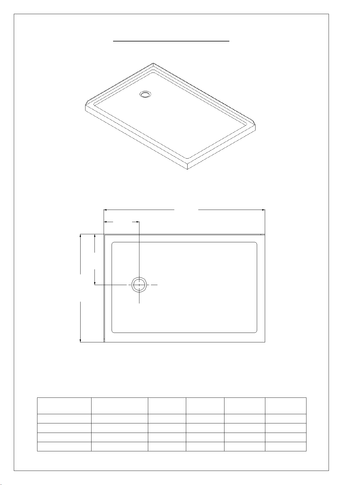
MODEL
SPECIFICATION
D (in)
W (in)
D1 (in)
W1 (in)
DLT-1034481
34"×48"
34"
48"
17"
12"
DLT-1036481
36"×48"
36"
48"
18"
12"
DLT-1036541
36"×54"
36"
54"
18"
12"
DLT-1036601
36"×60"
36"
60"
18"
12"
D
W
D1
W1
DOUBLE THRESHOLD SHOWER BASE
Left-Hand Drain Configuration
SLIMLINE SHOWER BASE manual Ver 5 Rev 9 03/2018
Page 13
©2018 DreamLine. All Rights Reserved
12
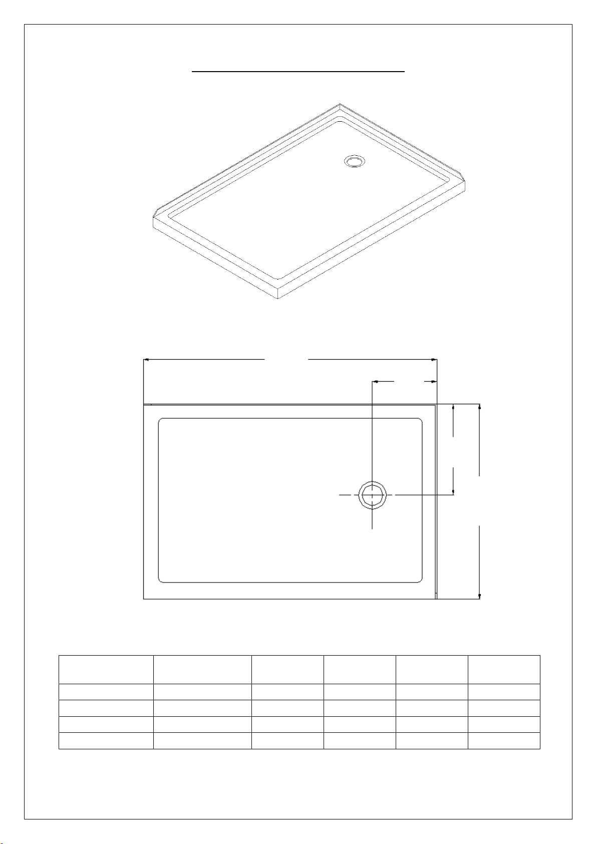
MODEL
SPECIFICATION
D (in)
W (in)
D1 (in)
W1 (in)
DLT-1034482
34"×48"
34"
48"
17"
12"
DLT-1036482
36"×48"
36"
48"
18"
12"
DLT-1036542
36"×54"
36"
54"
18"
12"
DLT-1036602
36"×60"
36"
60"
18"
12"
W D D1
W1
DOUBLE THRESHOLD SHOWER BASE
Right-Hand Drain Configuration
SLIMLINE SHOWER BASE manual Ver 5 Rev 9 03/2018
Page 14
©2018 DreamLine. All Rights Reserved
13
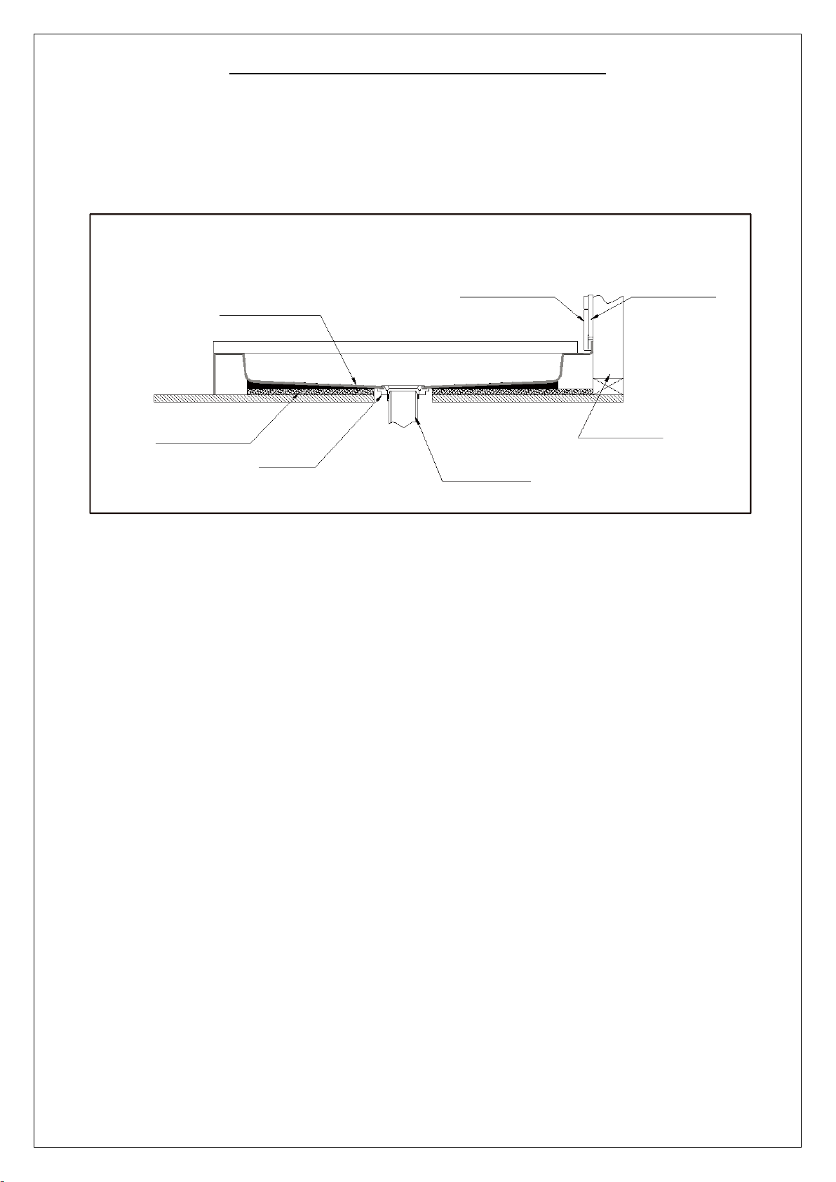
Finished Wall
Cement board
Shower Base
Mortar
Drain*
(2"×4") Stud
* not included
Shower Base Cross Section Diagram
SLIMLINE SHOWER BASE manual Ver 5 Rev 9 03/2018
Page 15
©2018 DreamLine. All Rights Reserved
14
(See Product Chart for Drain Location)
(5"×5") Opening
2" PVC Waste Pipe
90°
90°
90°
90°
90°
2" PVC Waste Pipe
(5"×5") Opening
(See Product Chart for Drain Location)
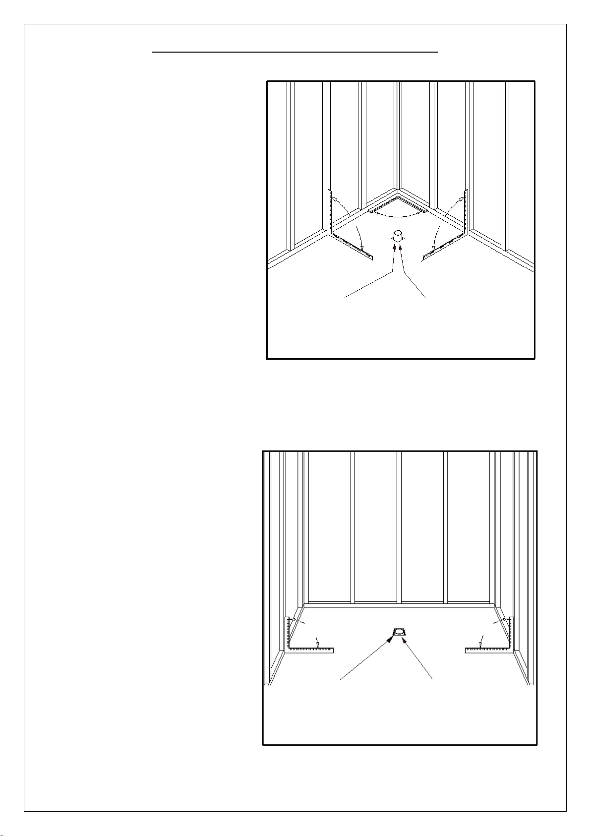
Shower Base Installation - Preparation
1. Ensure that the floor and the studs
are at right angles.
Provide a 5”×5” opening in the subfloor for the drain.
The 2” PVC waste pipe should
extend above the surface of the
sub-floor according to the drain
installation instructions and the
height of the Shower base.
Refer to the product drawings and
tables in this installation manual for
the drain location.
See Fig. 1 and Fig. 2 for details.
Fig. 1
Fig. 2
SLIMLINE SHOWER BASE manual Ver 5 Rev 9 03/2018
Page 16
©2018 DreamLine. All Rights Reserved
15
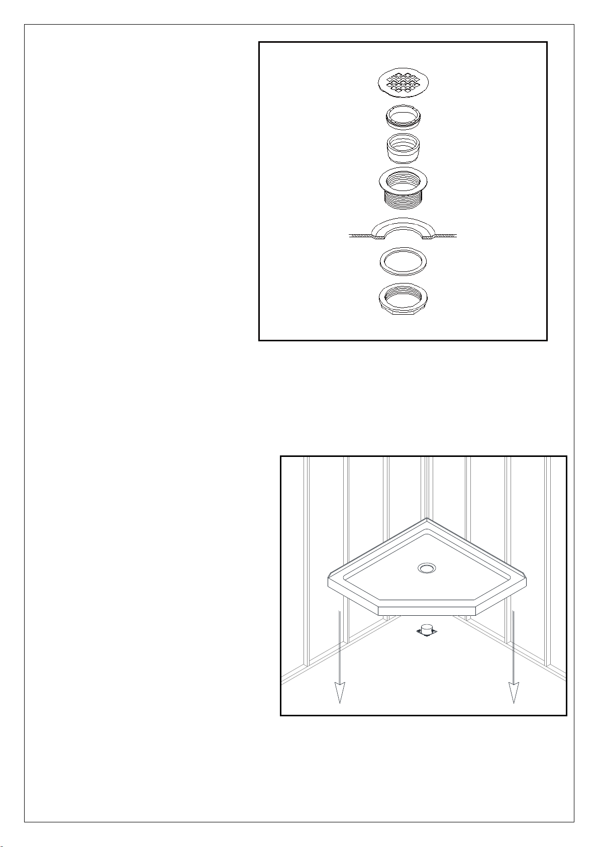
Lower the base over the drain pipe
and set it into place against the studs.
Fig. 4
2. Install the shower drain (NOT
INCLUDED) according to the
drain installation manual
(supplied with the drain).
See Fig. 3 for example
Fig. 3
3. Place the tray into the designated
position so that the Drain cutout drops
around the Drain Pipe and butt the
Shower Base up against the studs.
See Fig. 4 for details.
SLIMLINE SHOWER BASE manual Ver 5 Rev 9 03/2018
Page 17
©2018 DreamLine. All Rights Reserved
16
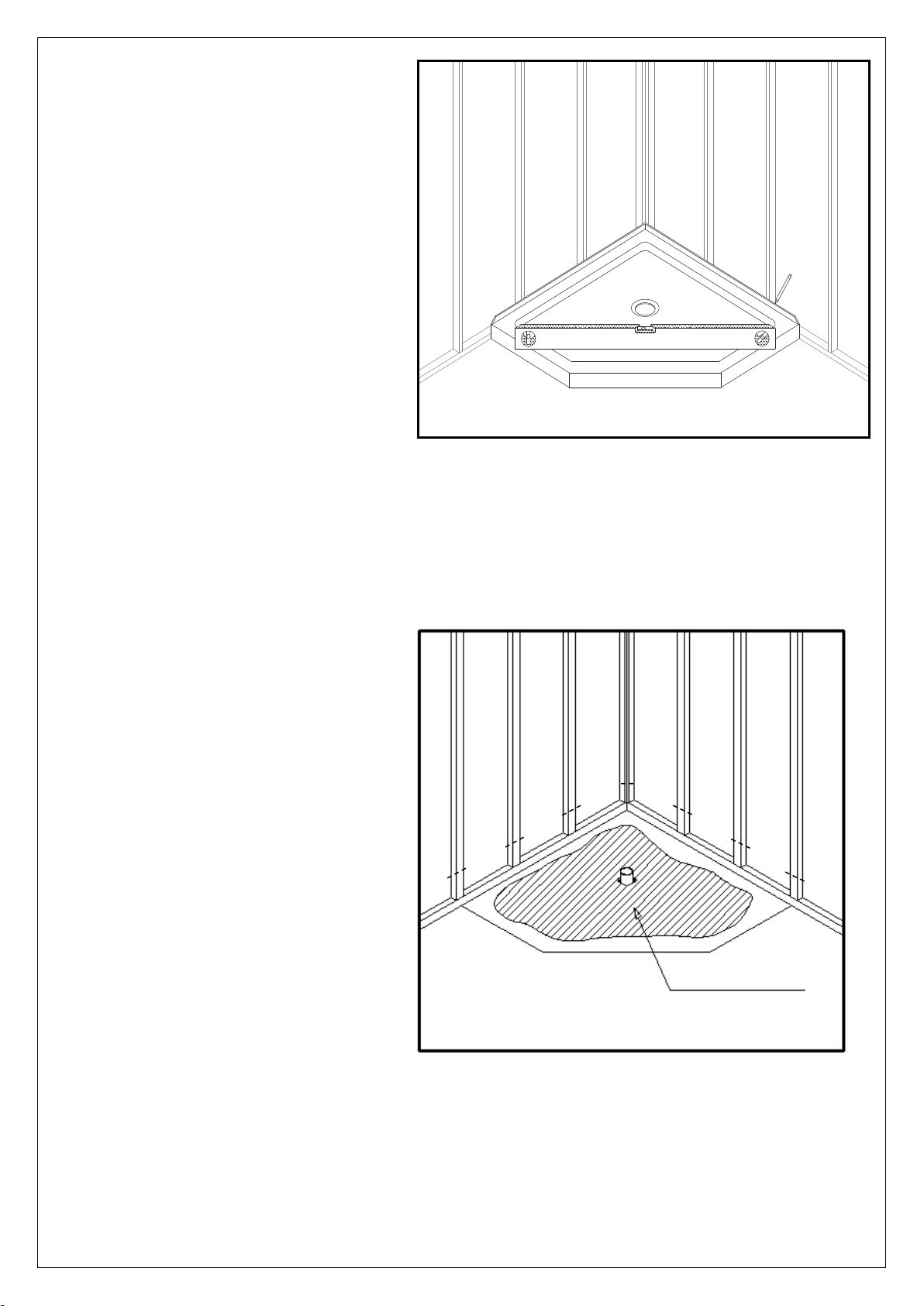
Level base in two directions
Mortar
Fig. 5
4. Level the tray and place marks on the
studs above the upper edge of the tile
flange.
See Fig. 5 for details.
5. Mix the bedding material (Mortar,
cement-sand mix, etc.) Concrete
or plaster is not recommended.
Apply enough bedding material
to support the entire bottom of
the shower base. This will add
additional stability and prevent the
base from shifting position.
See Fig. 6 for details.
SLIMLINE SHOWER BASE manual Ver 5 Rev 9 03/2018
Fig. 6
Page 18
©2018 DreamLine. All Rights Reserved
17
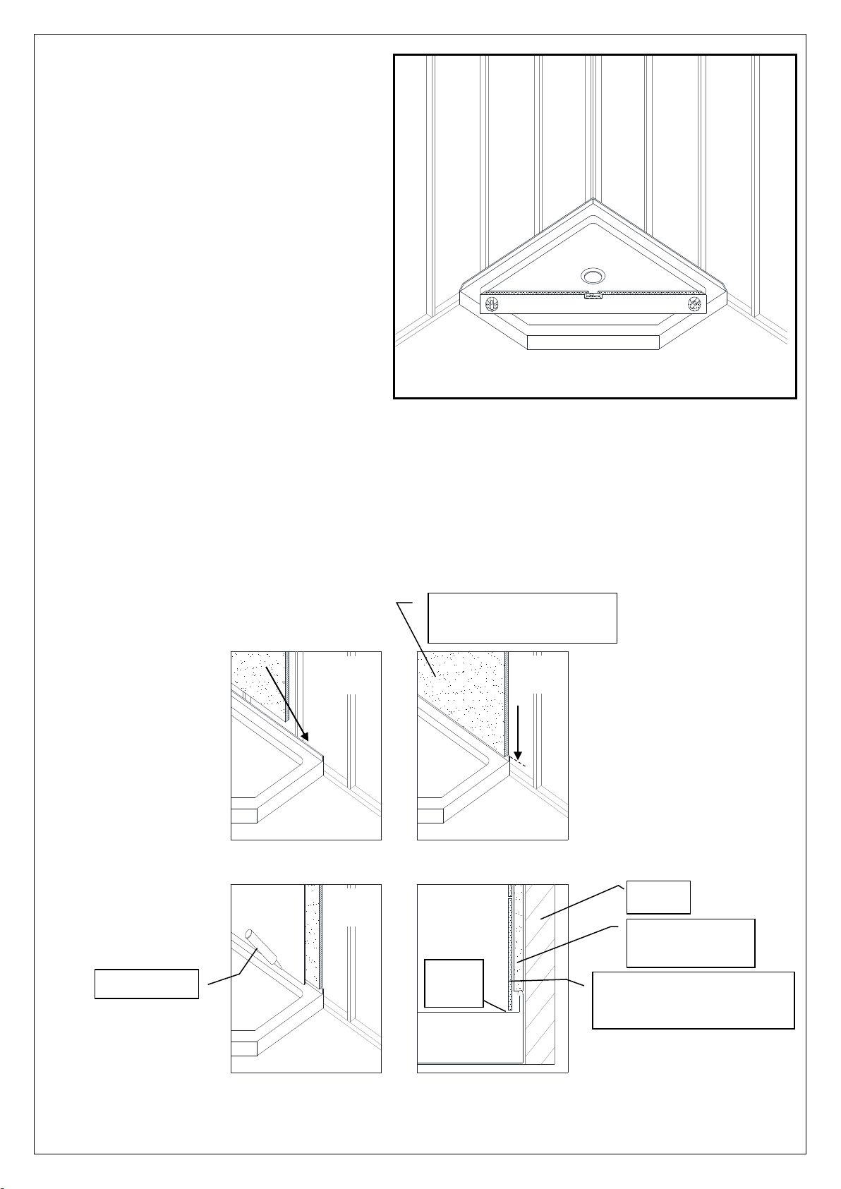
Fig. 7
Fig. 8
Waterproof Drywall to
the top of the tile flange
Caulk
Finished wall overlaps the
dry wall and tile flange
Stud
1
2
Waterproof
Drywall
4
3
Side View
1/8”
gap
Base
6. After the bedding material has been
poured and
shower base into the position with the
drain assembly sliding over the PVC
waste pipe. It will be necessary to push
the shower base until the top of the tile
flange aligns with the marks drawn on
the studs and the front edge is
contacting the rough floor along the
entire length of the shower base. Ensure
that the base is level in all directions.
You may need to use shims to hold the
tray level until the bedding fully sets.
Remove all excess mortar.
See Fig. 7 for details.
before
it sets, place the
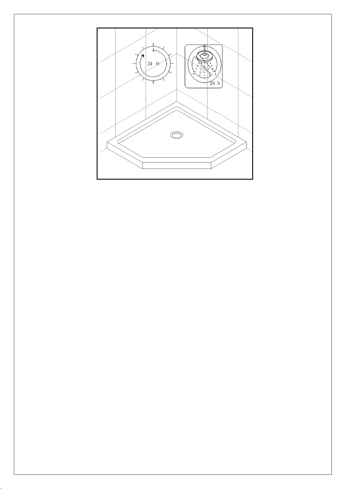
7. Allow the bedding material to completely harden before applying weight to the bottom of the
shower base.
Install the cement board (or the wallboard) above the tile flanges and secure it to the studs.
Put the tiles (or other finishing wall material) over the cement board leaving 1/8” gap between
the bottom of the tile or wall kit and the shower base. Use caulk to fill the gap.
See Fig. 8 and Fig. 9 for details.
SLIMLINE SHOWER BASE manual Ver 5 Rev 9 03/2018
Page 19
©2018 DreamLine. All Rights Reserved
18
Fig. 9
SLIMLINE SHOWER BASE manual Ver 5 Rev 9 03/2018
Page 20

©2018 DreamLine. All Rights Reserved
19
Product Maintenance
BASES and BACKWALLS: To ensure long lasting life for your acrylic base and/or back walls:
wipe them off after each use with a soft cloth. To clean the acrylic base or back walls use
non-abrasive sprays or cream based cleaners. Avoid the use of aerosol spray cleaners.
Never use abrasive cleansers, metal brushes or scrapers that could scratch or dull the surface.
GLASS: To ensure long lasting life for your glass shower products: wipe them off after each use
with a soft cloth. Rinse and wipe off the glass using either a soft cloth or a squeegee to prevent
soap buildup and water spots (Hard water can etch the surface of the glass over time if left to
dry). To prevent scratching the surface: never use abrasive cleaners or cleaning products that
contain scouring agents. Never use bristle brushes or abrasive sponges that may scratch the
surface.
HARDWARE: To ensure a long lasting finish: wipe off the metal parts after each use with a soft
cloth. Do not use abrasive cleaners or cleaning products containing ammonia, bleach or acid. If
accidentally used, rinse the surface as soon as possible to prevent damage to the finish
(peeling or corrosion). After cleaning the polished finishes, rinse thoroughly and wipe dry with
a soft cloth.
Clean stainless steel surfaces at least once a week. When applying stainless steel cleaner or
polish to stainless steel hardware, work with (not across) the grain. Never use an abrasive
sponge or cloth, steel wool or wired brush as these may permanently scratch the surfaces.
NOTE: To maximize the life of your door, it is important to regularly inspect the glass
and other hardware for misalignment, proper attachment, and/or damage. Contact
DreamLine with any questions or concerns.
SLIMLINE SHOWER BASE manual Ver 5 Rev 9 03/2018
Page 21

TEL: 866-731-2244
FAX: 866-857-3638
DREAMLINE.COM
For more information on DreamLine® Shower Doors and Enclosures please visit DreamLine.com
Page 22
Q-Wall 2
Acrylic Backwall Installtion Instructions
IMPORTANT
®
DreamLine
For the latest up-to-date technical drawings, manuals or additional details please refer to your model’s web
page on DreamLine.com
reserves the right to alter, modify or redesign products at any time without prior notice.
MODEL #s
SHBW-1241720-01
Please read these instructions carefully before installing. If you have any questions regarding installation, please
contact our technical support specialists Monday through Friday 8:00 AM – 7:00 PM EST at Phone:
1-866-731-2244, Fax: 1-866-857-3638 or e-mail our technical support group at [email protected]
®
For more information about DreamLine
Shower Doors & Tub Doors please visit DreamLine.com
Page 23

Preparation
1. Prior to installation, examine all boxes and packages for shipping damage and compare the piece
count with your packing slip. After opening all boxes and packages read this introduction carefully.
Check that all of the needed parts are included in the package by checking off the components on
the “Diagram of Acrylic Wall Components”. If the unit has been damaged, has a finishing defect, or
has missing parts, please contact our customer support department within 3 business days of the
delivery date. Please note that DreamLine® will not replace any damaged products or missing
parts free of charge after 3 business days or if the product has been installed. Feel free to
contact DreamLine
other proof of purchase to help us identify your original order.
2. Please note that you should consult your local building codes with questions on installation
compliance standards. Building and plumbing codes may vary by location, and DreamLine
not responsible for code compliance standards for your project and will not accept any
returns.
3. If this unit is going to be installed in a new construction, please install all of the required plumbing
and drainage before installing the shower. Use a competent and licensed (if required by local code)
plumber for all plumbing installation
®
if you have any questions, and please provide an order number, job name or
®
is
4. This acrylic wall system is specially designed to be installed over any solid surface. If you are
installing the acrylic walls over existing tiles, remove all loose tiles before the installation. If you are
installing over existing painted walls, remove all loose paint and apply a coat of primer. Please note
that some cutting and drilling may be necessary during the installation process.
5. Make sure to turn off the water supply, remove faucet, handles or any fixture trims protruding
from the wall. Clean the entire surface using regular household detergent removing soap film and
dirt from all wall surfaces and allow to dry.
6. Use an adhesive that is safe for use with acrylic and that will adhere to the surfaces that you are
applying it to. Follow the adhesive manufacturer’s instructions for the application of their product.
NOTE: The Q-Wall 2 is designed and sized to work best with DreamLine
®
Neo-angle,
Quarter-round and Square corner bases. The Quarter-round base is used as an example throughout
this manual.
2Q-Wall 2 manual Ver 3 Rev 2 11/2015
Page 24
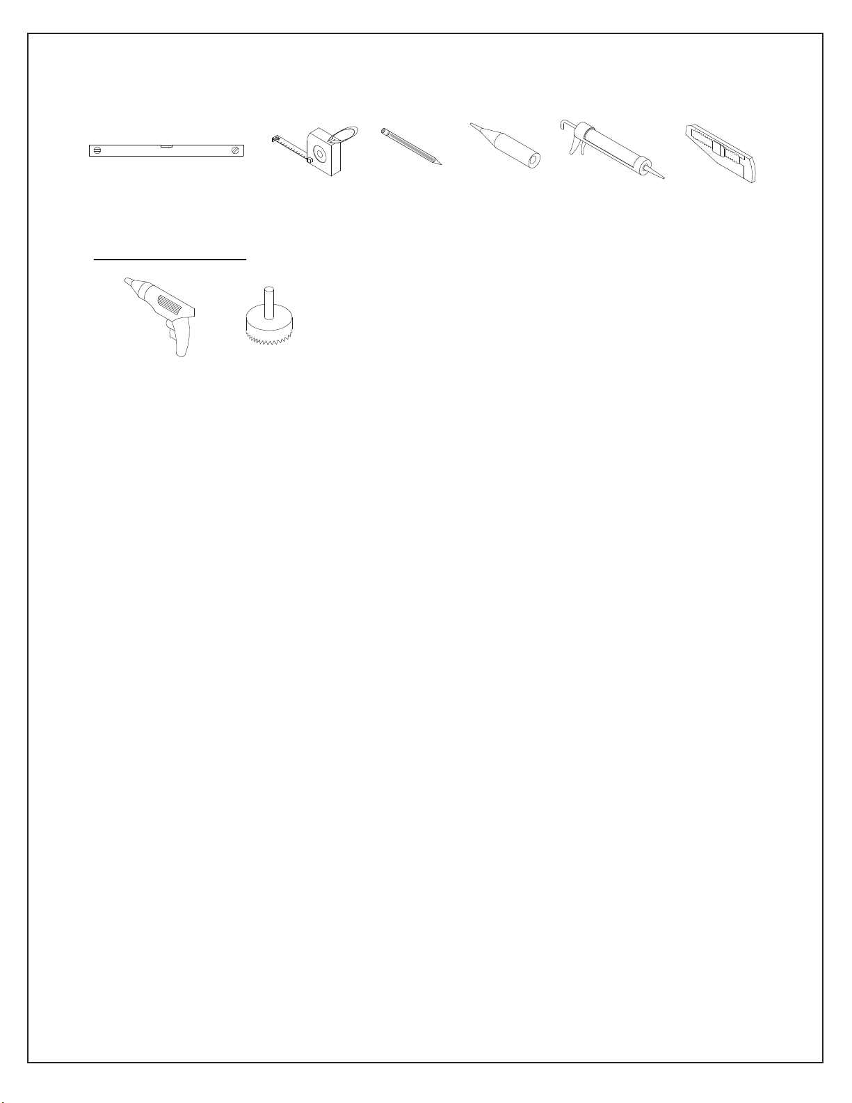
Required Tools
Level
OPTIONAL TOOLS
Power
Drill
Tape
Measure
Hole Saw
Pencil
Adhesive
Caulk
Razor Knife
NOTE: Unpack your unit carefully and inspect it. Identify all parts using the detailed diagram and
packing list in this manual as a reference. Before discarding the carton, check for small hardware
bags that may have fallen to the bottom of the box. If any parts are damaged or missing, please
contact DreamLine® for replacement. The shipping boxes may contain extra parts not used in your
model configuration.
NOTE: Retain these installation instructions for future reference.
3Q-Wall 2 manual Ver 3 Rev 2 11/2015
Page 25
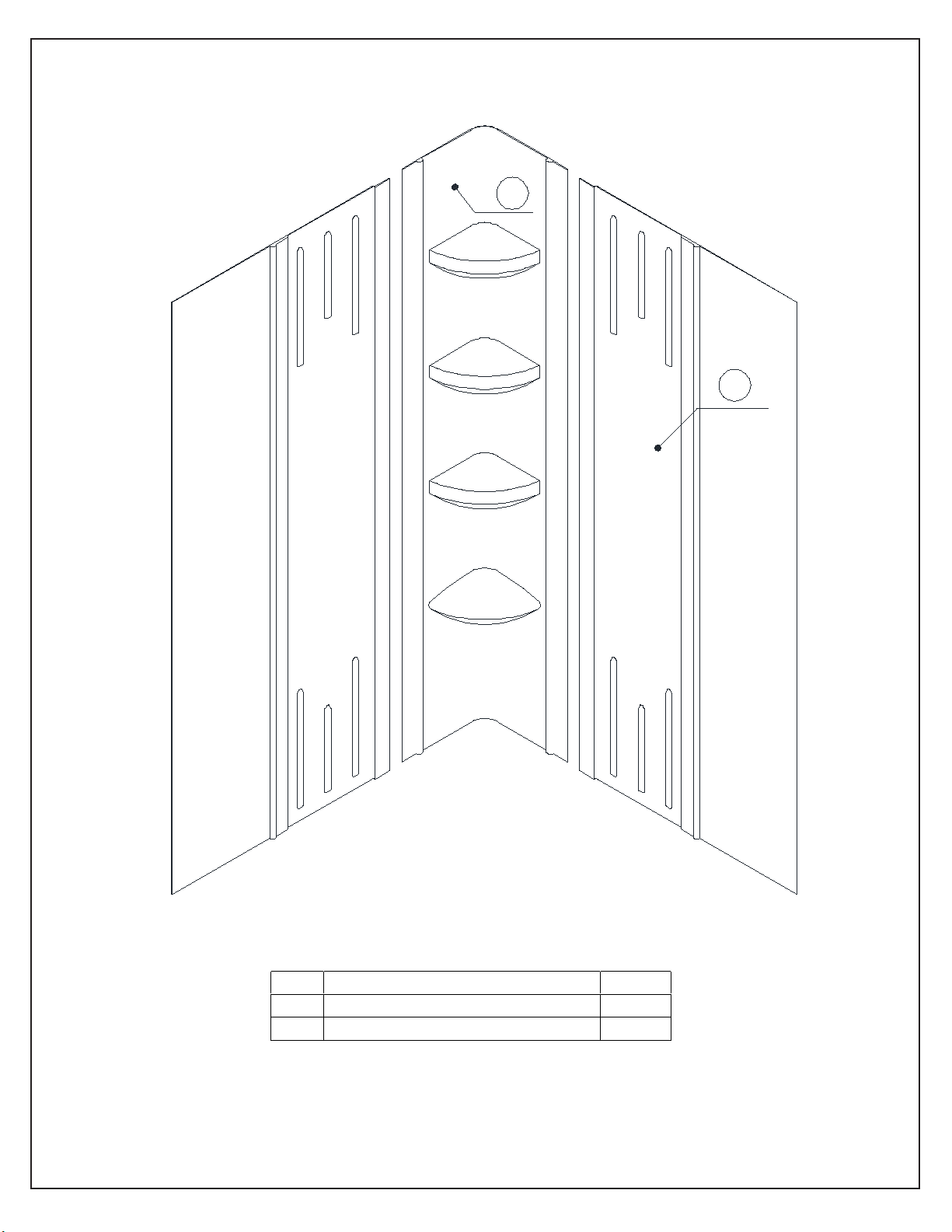
Diagram of Acrylic Back Wall Components
Part#
Description
Qty 01
Corner Acrylic Shelf Panel
1 pc
02
Side Acrylic Wall Panel
2 pcs
1
2
4Q-Wall 2 manual Ver 3 Rev 2 11/2015
Page 26
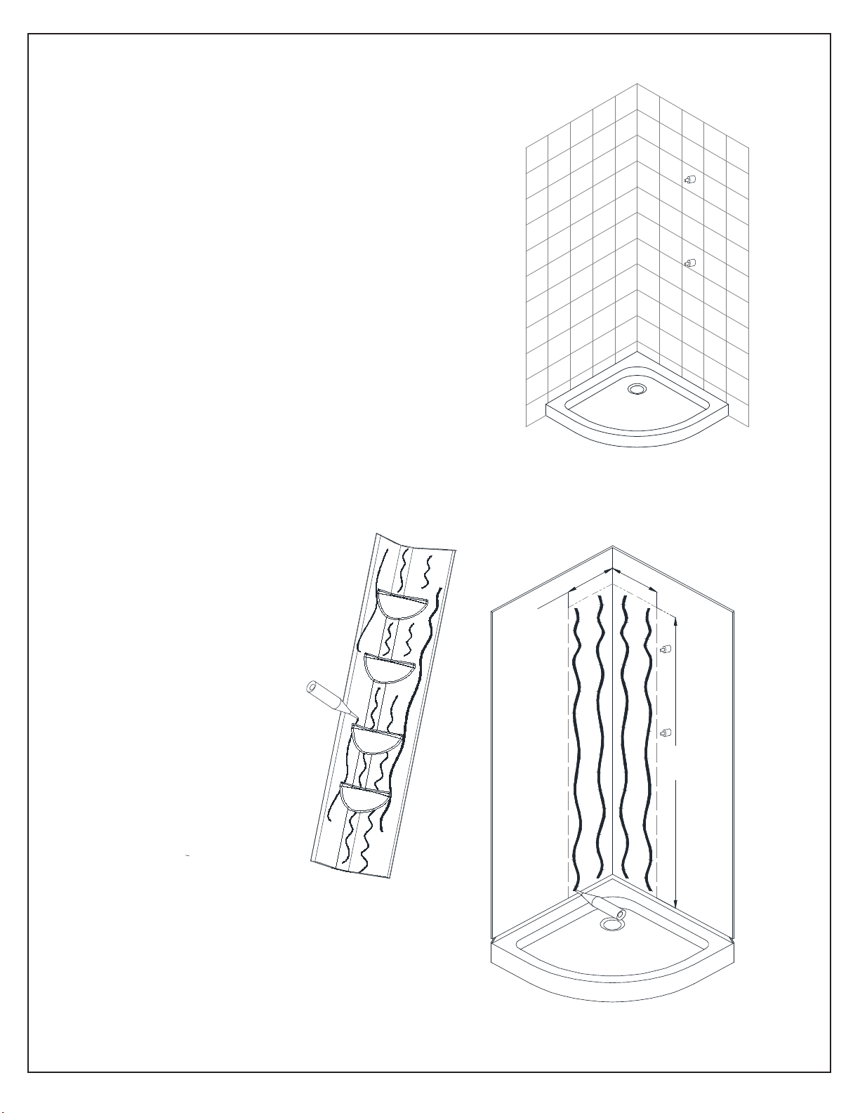
Installation steps
1. The shower base must be installed prior to
installation of the acrylic back wall kit.
Follow the manual instructions for proper
installation of the shower base.
Note: Acrylic wall panels can be installed onto
tile (Fig 1) or wallboard (Fig 2) Use the correct type
of adhesive designed for your particular wall
material that is also safe for use with acrylic.
2. Surface must be dry, smooth and free of any dust,
debris or any other contaminants. Run several beads of
adhesive on the Corner Acrylic Panel and along the wall
area where the Corner Acrylic Panel will attach,
extending at least 11” out from the corner to a height of
71-1/2”.
e
l
i
T
Fig 1
See Fig 2 and Fig 3 for details.
apply adhesive to
the back surface of
the acrylic corner
panel
Fig 2
11”
(280mm)
d
r
a
o
b
l
l
a
W
71-1/2”
(1816mm)
Note: Adhesive should only be applied to one panel
at a time, otherwise it may start to set before you
are ready to attach the panels. Consult the adhesive
manufacturer’s guidelines for specific information.
Fig 3
5Q-Wall 2 manual Ver 3 Rev 2 11/2015
Page 27
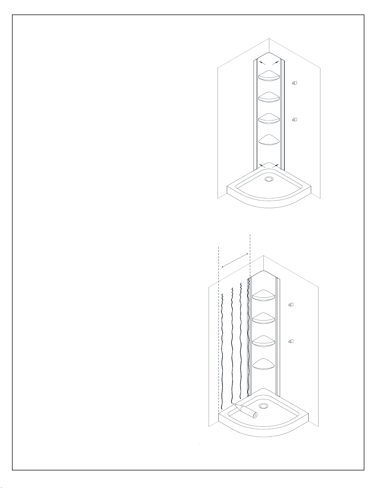
3. Place the Corner Acrylic Panel into position in the
corner and apply pressure to the entire surface from
top to bottom to ensure good overall contact.
The bottom of the Corner Acrylic Panel should make
contact with the shower base.
See Fig 4 for details.
Fig 4
4. Install the Side Acrylic Wall Panel on the wall
opposite of the shower fixtures first. Run several
beads of adhesive throughout the area where the
Side Acrylic Wall Panel will attach to the wall up
to the edge of the base threshold (including the
section of the Corner Acrylic Panel where the
Side Acrylic Wall Panel will overlap).
See Fig 5 for details.
NOTE: If you intend to trim your Side Acrylic Wall
Panels flush to the edge of the base/threshold, then
apply adhesive up to that area.
If you intend to allow the Side Acrylic Wall Panels
to extend beyond the base/ threshold, then apply
adhesive up to that area.
Fig 5
6Q-Wall 2 manual Ver 3 Rev 2 11/2015
Page 28
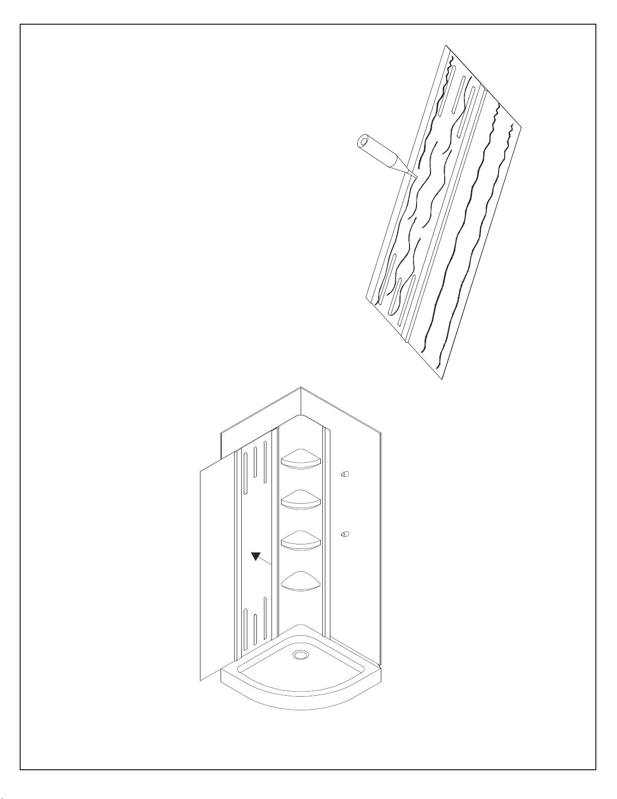
5. Place the Side Acrylic Wall Panel in position
on the wall and apply pressure to the entire
surface from top to bottom to ensure good
overall contact.
Position the Side Acrylic Wall Panel so that the
top is flush with the Corner Acrylic Panel.
The bottom of the Side Acrylic Wall Panel
should make contact with the shower base.
DO NOT trim the width to size yet.
See Fig 6 and 7 for details.
Fig 6
Fig 7
7Q-Wall 2 manual Ver 3 Rev 2 11/2015
Page 29
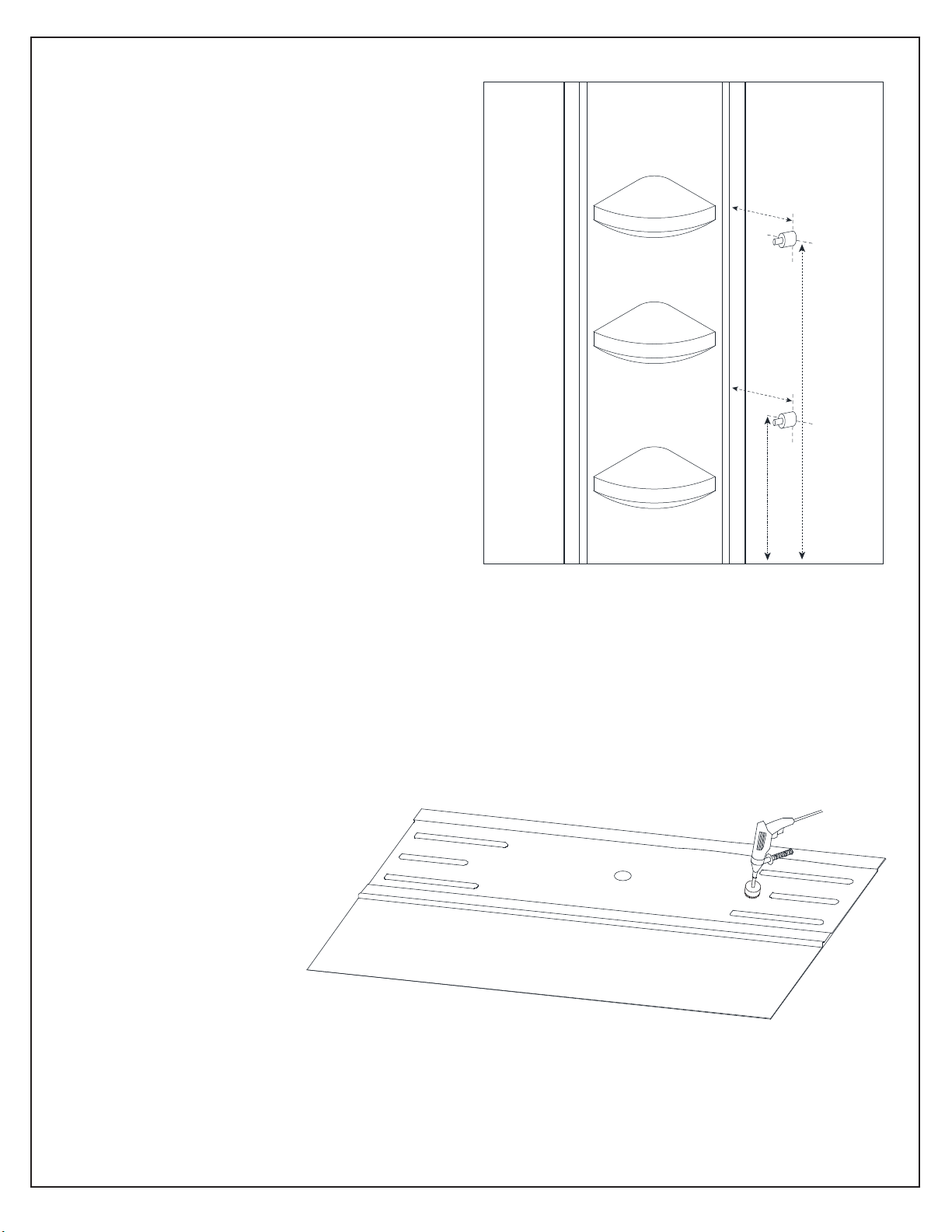
6. Carefully measure the positions of the fixtures
relative to the Corner Acrylic Panel and drill
holes in the Side Acrylic Wall Panel with your
power drill using a hole saw attachment of the
proper diameter, which will accommodate the
shower head and mixing valves. Make sure that
all plumbing fixtures will easily fit through the
Side Acrylic Wall Panel and that the fixture
escutcheons (or trim rings) will completely cover
the holes.
See Fig 8 and Fig 9 for examples.
Fig 8
Fig 9
8Q-Wall 2 manual Ver 3 Rev 2 11/2015
Page 30
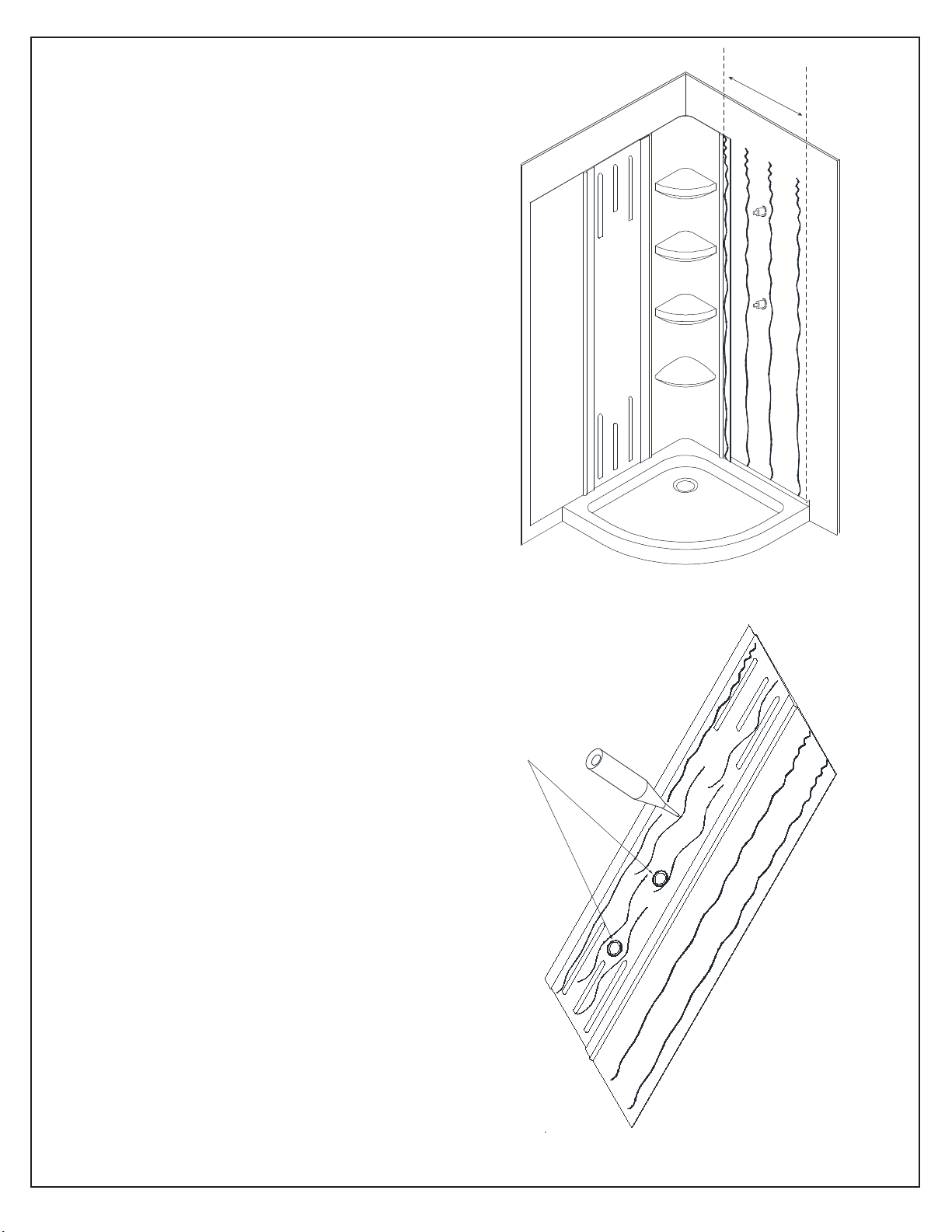
7. Before installation, dry fit the Side Acrylic Wall
Panel to check the holes for proper alignment around
the fixtures.
Run several beads of adhesive on the wall throughout
the area where the Side Acrylic Wall Panel will attach,
up to the edge of the base/threshold (including the
section of the Corner Acrylic Panel where the Side
Acrylic Wall Panel will overlap).
See Fig 10 and Fig 11 for details
NOTE: If you intend to trim your Side Acrylic Wall
Panels flush to the edge of The base/threshold, then
apply adhesive up to that area.
If you intend to allow the Side Acrylic Wall Panels
to extend beyond the base/ threshold, then apply
adhesive up to that area.
Make sure to apply silicone
around the hole cutouts.
Fig 10
Fig 11
9Q-Wall 2 manual Ver 3 Rev 2 11/2015
Page 31
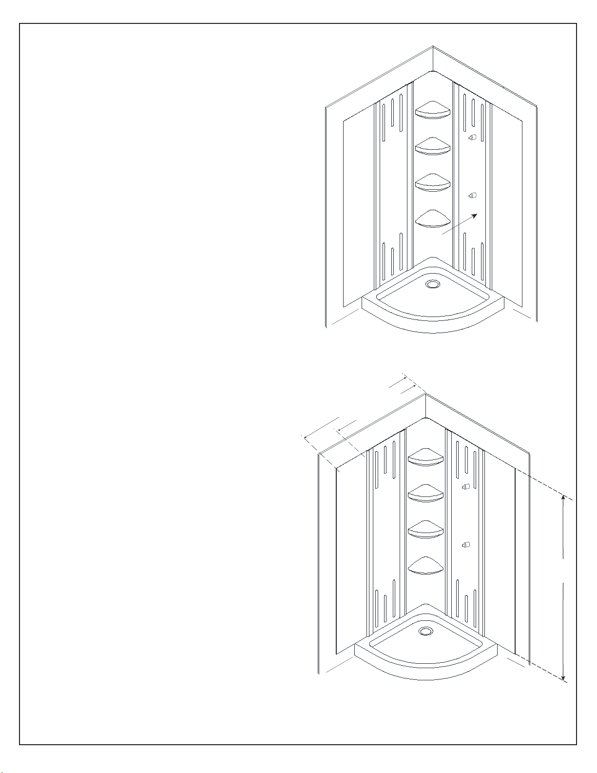
8. Place the Side Acrylic Wall Panel in
position on the wall and apply pressure to
the entire surface from top to bottom to
ensure good overall contact.
Position the Side Acrylic Wall Panel so that
the top is flush with the Corner Acrylic
Panel. The bottom of the Side Acrylic Wall
Panel should make contact with the shower
base.
See Fig 12 for details.
9a. Using a razor knife and a straight edge, trim the
Side Acrylic Wall Panel to the desired width by
scoring the acrylic wall surface and removing the
excess.
See Fig 13 for details.
40-1/2” max
29-7/8” min
Fig 12
72-7/8”
Fig 13
10Q-Wall 2 manual Ver 3 Rev 2 11/2015
Page 32
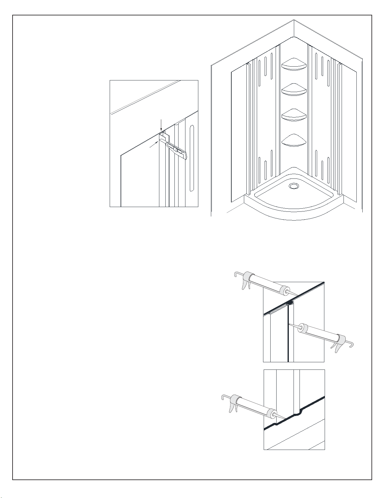
®
9b. If installing a DreamLine
enclosure, you may
determine the position of the enclosure and trim the
Side Acrylic Wall Panel flush with the outside edge
of the wall profiles.
See Fig 14 for details.
Enclosure wall profile
10. Clean any excess adhesive from around the acrylic
wall edges and apply a bead of silicone or caulk to the
vertical and horizontal outside seams where the panels
are joined and where they meet the threshold and also
along the top edges.
See Fig 15 for details.
Note:
Remove any air bubbles or gaps from the walls prior to
sealing the edges by applying pressure to the surface
and moving towards the nearest edge.
Fig 14
Fig 15
11Q-Wall 2 manual Ver 3 Rev 2 11/2015
Page 33
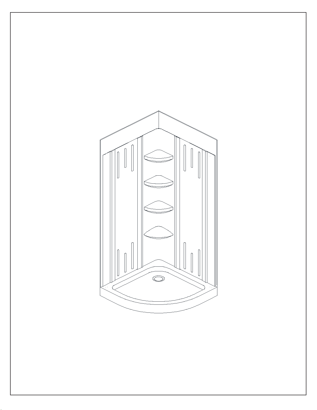
11. Continue with the installation of the shower enclosure per your model’s instructions.
Allow 24 hours for the adhesive and silicone/caulk to cure before using.
See Fig 16 for details.
Fig 16
12Q-Wall 2 manual Ver 3 Rev 2 11/2015
Page 34

Product Maintenance
Acrylic cleaning procedure:
Acrylic should be cleaned with warm water and a clean, non-abrasive cloth. If desired, a mild,
non-abrasive detergent may also be used. Use only light pressure when cleaning. Avoid rubbing
dirt or grit into the surface. Turn the cloth often and replace with a clean cloth frequently. Dry by
blotting gently with a clean, dry cloth.
DO NOT USE:
Window cleaning sprays, alcohol, kitchen abrasive compounds, or solvents (such as acetone,
gasoline, or thinners). Do not use ammonia based cleaning solutions on the acrylic as it will
damage the surface.
How do you get scratches out of Acrylic?
For light scratches, use a buffing compound such as a car wax. Use a buffer or lightly polish the
surface by hand until scratches disappear.
13Q-Wall 2 manual Ver 3 Rev 2 11/2015
Page 35

For more information on DreamLine
TEL: 866-731-2244
FAX: 866-857-3638
DREAMLINE.COM
®
Shower Doors and Enclosure please visit DreamLine.com
 Loading...