

Falcon Controller Manual
Product Features:
3 Mode: Wired, 2.4G wireless, Bluetooth
Support PC (Windows), Android
L4 L5 R4 R5 Back Paddle
L4 L5 R4 R5 Mapping switch
Xinput (Wired) + Dinput (Bluetooth) + Xinput (2.4G)
Include USB dongle
LED indication for each Mode
Powered by two AA Batteries
Precise Hall Sensor Triggers
Trigger lock support quick shot for FPS games
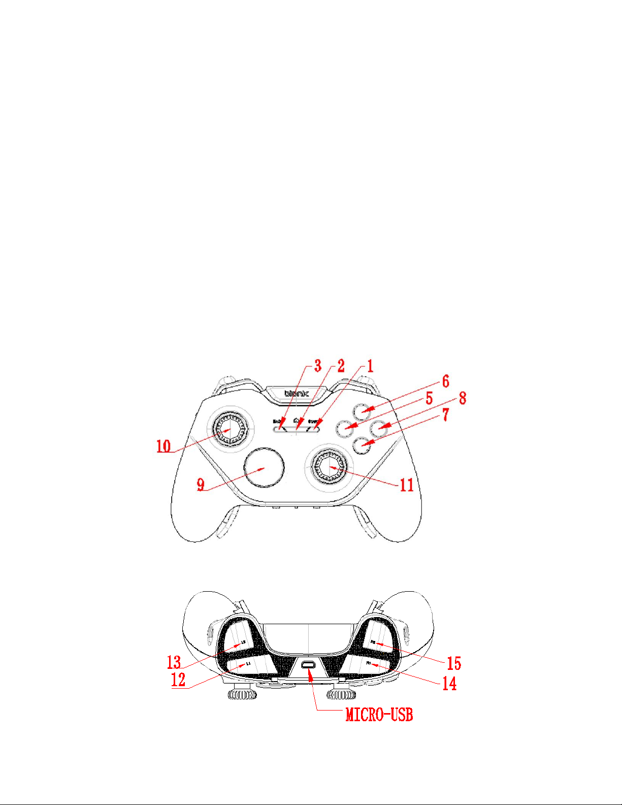
Button List:
Wired
Android (Bluetooth)
Windows (2.4G)
NO
Button
USB with Xinput
Bluetooth Dinput Mode
2.4G Xinput Mode
1 1 BACK
KEYCODE_BACK
BACK
2 2 Xbox Home
KEYCODE_HOME
Xbox Home
3 3 START
KEYCODE_START (0x13B)
START
5
(X)
BUTTON
X
Keycode_Button_X
X
6
(Y)
BUTTON
Y
Keycode_Button_Y
Y
7
(A)
BUTTON
A
Keycode_Button_A
A
8
(B)
BUTTON
B
Keycode_Button_B
B
9
D-PAD UP
D-Pad
Keycode_DPAD_UP
D-Pad
D-PAD
DOWN
Keycode_DPAD_DOWN
D-PAD
LEFT
Keycode_DPAD_LEFT
D-PAD
RIGHT
Keycode_DPAD_RIGHT
10
(L3)
BUTTON
analog
stick
Left Stick Button
Keycode_Button_THUMB L
Left Stick Button
11
(R3)
BUTTON
analog
stick
Right Stick Button
Keycode_Button_THUMB R
Right Stick Button
12
(L1)
BUTTON
LB
Keycode_Button_L1
LB
13
(L2)
BUTTON
LT
AXIS_BRAKE (0.0 to 1.0)
&
Keycode_Button_L2
LT
14
(R1)
BUTTON
RB
Keycode_Button_R1
RB
15
(R2)
BUTTON
RT
AXIS_GAS (0.0 to 1.0)
&
Keycode_Button_R2
RT
10
LEFT
ANALOG
Left Stick
AXIS_X (-1.0 to 1.0) AXIS_Y (-1.0 to
1.0)
Left Stick
11
RIGHT
ANALOG
Right Stick
AXIS_Z (-1.0 to 1.0) AXIS_RZ (-1.0 to
1.0)
Right Stick
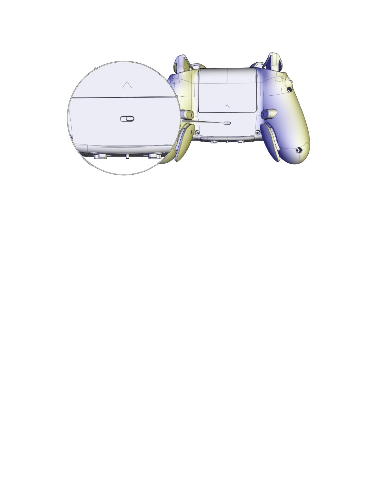
Mode Switch:
Left Mode: Bluetooth Mode
Right Mode: 2.4G Mode
USB Mode will be activated when connect the USB cable to the PC.
Bluetooth Mode:
Bluetooth Pairing:
1. Install two AA batteries into the battery bay
2. Slide the Mode switch to left side
3. Holding Home button for 5 secs until the LED quick flash in Blue, now the controller
entering the Bluetooth Pairing mode
4. Go to the Bluetooth setting on the Android device, click the “Bionik Falcon Controller” to
connect
5. The LED will stay on Blue when success connected
6. If not success, please turn off the controller then repeat step 2 to 5
Bluetooth Connect: (Success connected with the Android before)
1. Once the controller Success connected with the Android, player could simply press the
Home button to connect back the Android device
2. The LED will slow flash in Blue to searching the Android device
3. LED will stay on Blue when success connected

2.4G Mode:
1. Insert the USB dongle to the USB port of PC
2. Install two AA batteries into the battery bay
3. Slide the Mode switch to right side
4. Single press the Home button to connect to the USB dongle, the LED will slow flash in
Green until success connected
5. LED will stay on GREEN when success connected
6. Go to “Game Controller” at the Control Panel to test the controller
Button Mapping:
L3, L4, R3 and R4 button could be mapping to the designed button by 4 switchs.

Mapping function ON/OFF Switch:
Slide Up to Turn OFF the mapping functions
Slide Down to Turn ON the mapping functions
Low Power:
At the Bluetooth and 2.4G Mode, the LED will slow flash (10s once) when the battery in low.
Trigger Lock:
Slide the trigger lock to the controller top to Turn the trigger to FPS Mode with shorter
travel distance
Slide the trigger lock to the controller back to Turn the trigger to Normal Mode with full
travel distance


FCC Warnings
This device complies with part 15 of the FCC Rules.
Operation is subject to the following two conditions:
(1) This device may not cause harmful interference, and
(2) this device must accept any interference received, including interference that may
cause undesired operation.
Note: This equipment has been tested and found to comply with the limits for a Class B
digital device, pursuant to Part 15 of the FCC Rules. These limits are designed to
provide reasonable protection against harmful interference in a residential installation.
This equipment generates, uses and can radiate radio frequency energy and, if not
installed and used in accordance with the instructions, may cause harmful interference
to radio communications.
However, there is no guarantee that interference will not occur in a particular installation.
If this equipment does cause harmful interference to radio or television reception, which
can be determined by turning the equipment off and on, the user is encouraged to try to
correct the interference by one or more of the following measures:
Reorient or relocate the receiving antenna.
Increase the separation between the equipment and receiver.
Connect the equipment into an outlet on a circuit different from that to which the
receiver is connected.
Consult the dealer or an experienced radio/TV technician for help.
Warning: Changes or modifications to this unit not expressly approved by the part
responsible for compliance could void the user’s authority to operate the equipment.
FCC Radiation Exposure Statement
The device has been evaluated to meet general RF exposure requirement.
The device can be used in portable exposure condition without restriction.
Declaration of Conformance
DREAM GEAR,LLC declares that the radio equipment type BNK-9014 is in complaince
with Directive 2014/53/EU
 Loading...