

Page 1

10 series
User Guide Docking Station
English
Page 2

dreamcom 10 series
Docking Station
User Guide
Tec hnical Support
Dreamcom Corporation
Tittwiesenstrasse 27
7000 Chur, Switzerland
Telephone: +41 81 300 43 50
Contact email: [email protected]
For additional information, please visit the Dreamcom Web site: www.dreamcom.ch
Copyright © 2008 Dreamcom Corporation
All Rights Reserved.
Page 3

Introduction 3
Features 4
Hardware tour 5
Top view 5
Left view 6
Right view 7
Bottom view 8
Using the docking station 9
Installing the battery pack 9
Charging the battery 10
Docking the computer 12
Turning the system on 13
Turning the system off 13
Undocking the computer 14
Adjusting the computer position 16
Contents
Connecting peripherals 21
USB devices 21
External monitor 21
External keyboard 21
External pointing device 22
Printer 22
Audio devices 22
Video devices 22
ExpressCard 22
MultiMedia cards 23
IEEE 1394 devices 24
TV signal source (not supported in business version) 24
Replacing the hard disk drive module 26
Tool requirements 26
ESD (Electrostatic Discharge) precautions 26
Specifications 30
User support 31
Index 33
Page 4

Introduction
Congratulations on your purchase of the dreamcom 10 series docking
station. The docking station transforms your dreamcom 10 notebook
computer into a full-featured desktop workstation. This compact and light
portable expansion module comes with a unique rotating holder that allows
you to position the computer in various angles. Its innovative docking
mechanism provides secure and easy installation.
The docking station also features video capabilities to provide connections
for multiple displays and peripherals simultaneously. The S/PDIF digital
audio interface connects digital audio equipment such as a digital audio
tape machine or audio processing device. It also includes a nextgeneration ExpressCard 34/54 card slot and a 5-in-1 card reader for
optional MultiMedia card, Secure Digital card, Memory Stick, Memory Stick
Pro, or XD-Picture card. A built-in TV tuner on the docking station allows
viewing of standard analog television broadcast directly to your notebook
computer and an option for viewing digital television broadcast is available
when you connect the DVB-T digital TV antenna to the TV tuner. The
docking station also features additional hard drive bay that accommodates
up to two 2.5-inch SATA hard disk drives and provides easy backup of data
stored on your computer’s internal hard drive.
3
Page 5

Features
Human-centric design and ergonomics
• Sleek, smooth, slim and stylish design
• Adjustable to different angles for comfortable tilt position and
ergonomic viewing
• Holds the dreamcom 10 notebook computer securely
• Fits easily into any laptop bag
Multimedia
• Two built-in speakers
Storage
• Two 2.5-inch hard disk drive bay (SATA interface)
Features4
• ExpressCard slot (ExpressCard 34/54 module)
• MultiMedia card slot
Connectivity
• IEEE 1394 (4-pin)
• TV input port
• Four USB 2.0 ports
• Audio in /S/PDIF In port
• Audio out/S/PDIF out port
• S-video out port
• HDMI port
• CRT/VGA port
• Ethernet LAN
• ExpressCard slot (ExpressCard 34/54 module)
• MultiMedia card slot (SD/MMC/MS/MS-Pro/XD)
• DC-in jack for AC adaptor
Page 6
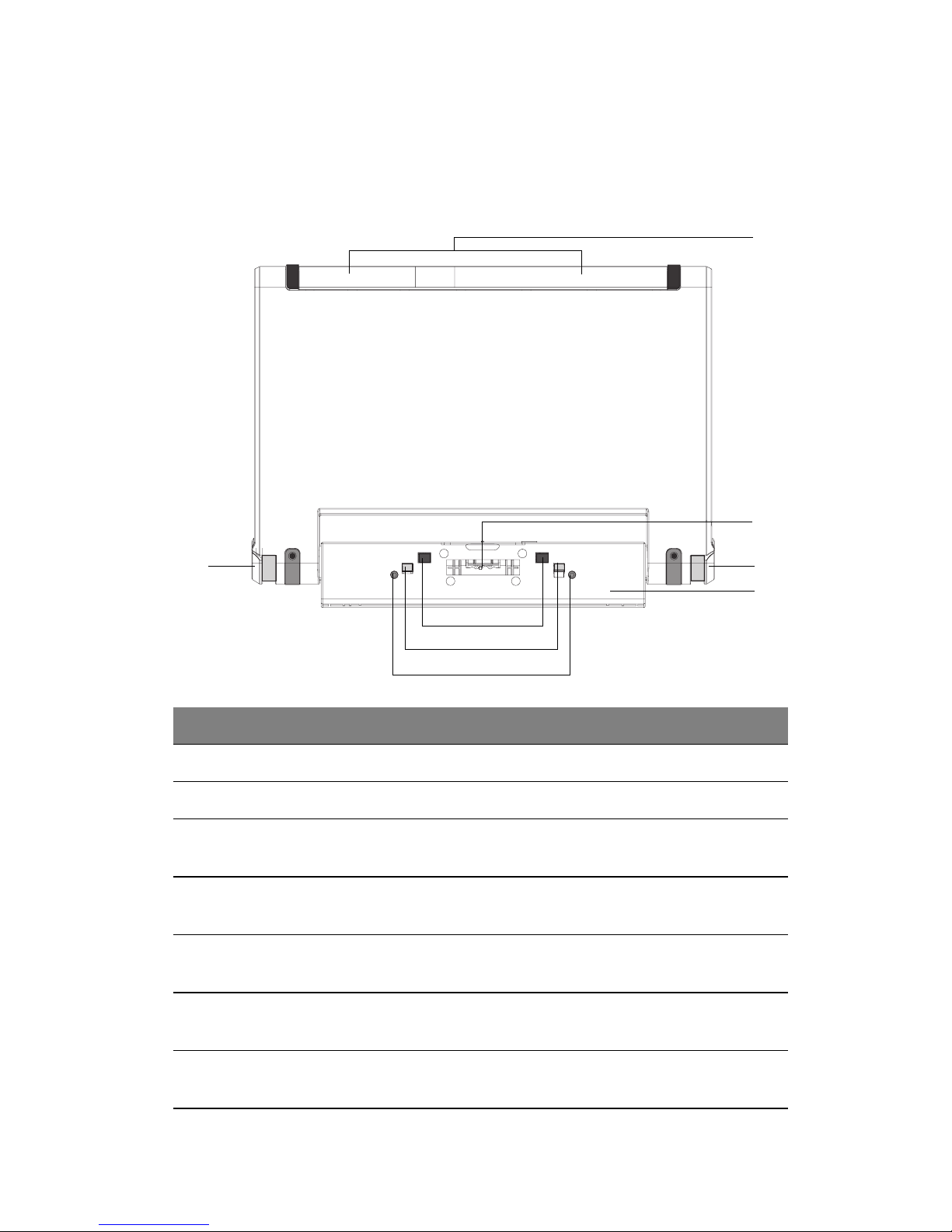
Hardware tour
Top view
5
1
2
33
4
5
6
7
# Item Description
1 Speakers Outputs sound.
2 Docking connector Connects to the computer.
3 Eject buttons
(left and right)
4 Rotating handle Allows you to adjust the position of the docking station
5 Docking eject pins Disconnects the computer from the docking station
Simultaneous pressing of the eject buttons undock the
computer from the docking station.
and computer.
docking connector when the eject button is pushed.
6 Docking restraint
brackets
7 Docking alignment
pins
Secures the computer to the docking station.
Fits to the computer docking alignment slots to align
the computer to the docking station.
Page 7
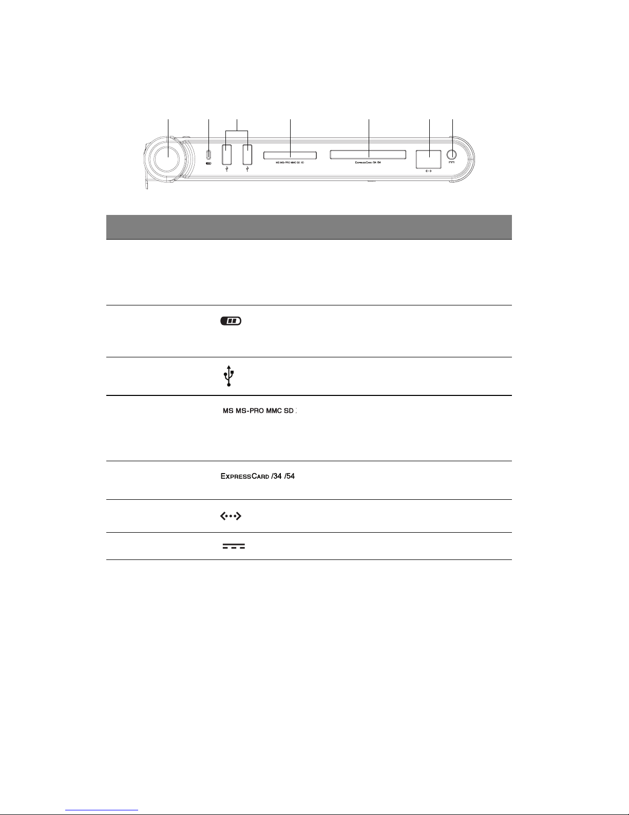
Left view
123 4 5 67
# Item Icon Description
Hardware tour6
1 Left eject
button
2 Charge LED
indicator
3 USB ports Connect to USB devices (e.g., USB
4 MultiMedia
card slot
5ExpressCard
34/54 slot
6 Network jack Connects to an Ethernet-based network.
7 DC-in jack Connects to an AC adapter.
Simultaneous pressing of the left eject
button with the right eject button will
undock the computer from the docking
station.
Indicates the docking station’s battery is
being charged. The indicator light goes
off when the battery is fully charged.
digital camera).
Accepts a Secure Digital (SD), Memory
Stick (MS), Memory Stick-Pro (MS-Pro),
MultiMedia Card (MMC), or xD-Picture
Card (xD) memory card.
Accepts an ExpressCard 34/54 module.
Page 8
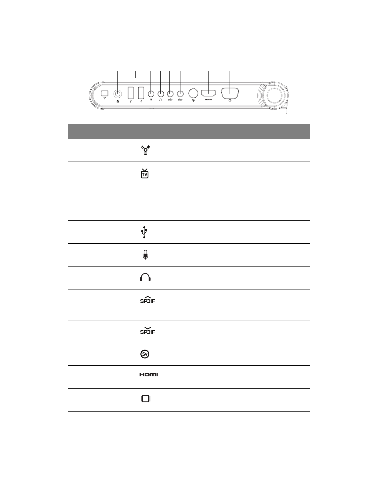
Right view
1 2 3 7 10 114 5 6 8 9
# Item Icon Description
1 IEEE 1394 port Connects to a IEEE 1394-compatible (4-pin)
device (e.g., digital video camera).
2 TV input jack Connects to an analog TV signal cable to view
local or basic cable channels.
Connects to a digital TV signal cable through the
provided DVB-T digital TV antenna to view digital
TV channels.
Note: Not supported in business version.
7
3 USB ports Connects to USB devices (e.g., USB digital
camera).
4 Microphone
jack
5 Headphone-
out jack
6 S/PDIF line-out
jack
7 S/PDIF line-in
jack
8 S-video out
port
9 HDMI port Connects to an external video device (e.g.
10 VGA port Connects to an external display device (e.g.
Inputs sounds and voices into your computer.
Connects to a headphone.
Connects to audio line-out devices (e.g.
speakers, headphones); supports S/PDIF
connections.
Accepts audio line-in devices and supports S/
PDIF connections.
Connects to a television or display device with
S-video input.
DVD multimedia player, set top box).
external monitor, LCD projector).
Page 9
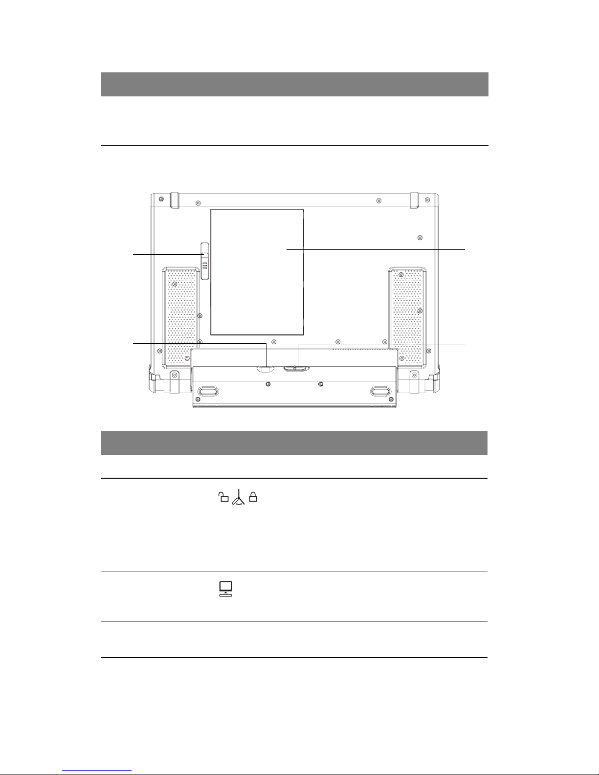
# Item Icon Description
Hardware tour8
11 Right eject
button
Bottom view
4
3
Simultaneous pressing of the right eject button
with the left eject button will undock the computer
from the docking station.
1
2
# Item Icon Description
1 Battery cover Remove cover to install the battery pack.
2 Docking
rotation latch
Slide latch towards the unlock icon to release
the docking station handle, then rotate the
handle by
Slide latch towards the lock icon to keep the
docking station handle locked and secured in
0°, 80°, or 174° position.
0°, 80°, or 174° position.
3 Application
release latch
4 Battery cover
latch
Slide the latch down to request the operating
system to undock the computer from the
docking station.
Locks and releases the battery cover.
Page 10
Using the docking station
This section includes instructions on the following procedures:
• Installing the battery pack
• Charging the battery
• Docking the computer
• Turning the system on
• Turning the system off
• Undocking the computer
Installing the battery pack
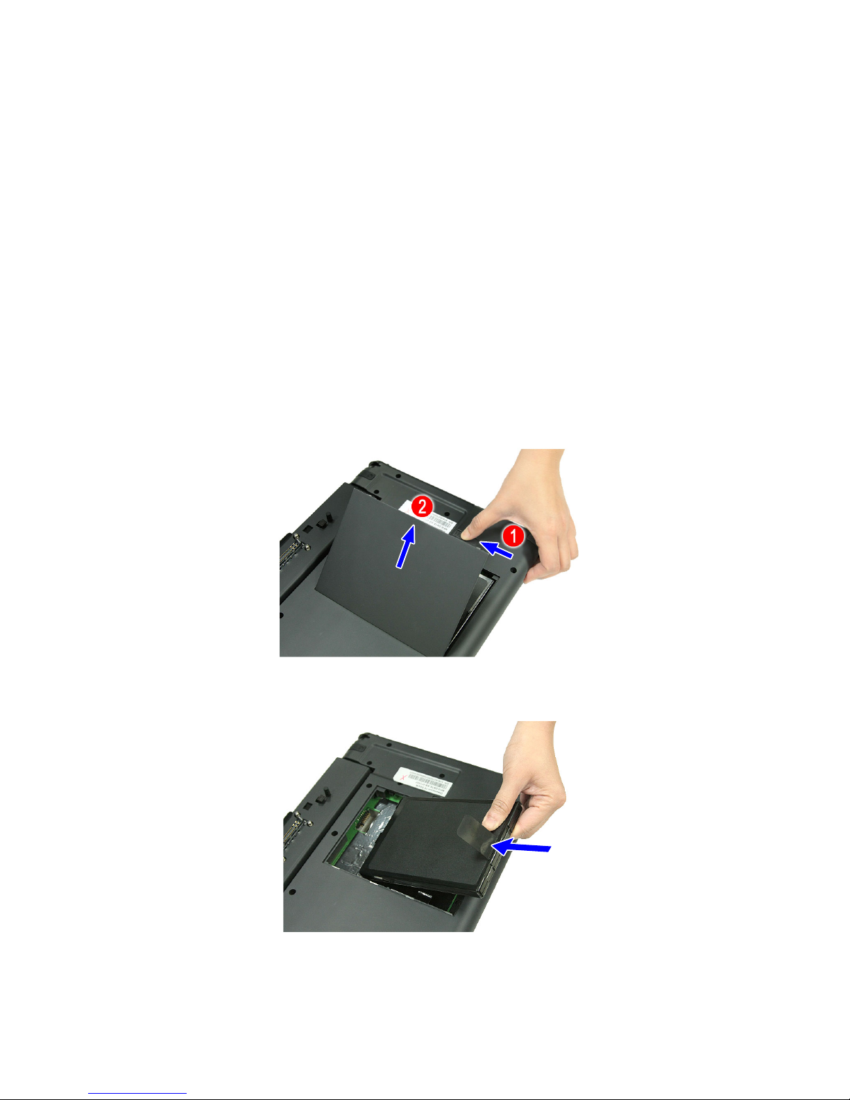
1. Slide the battery cover latch to the left (1), then remove the battery
cover (2).
9
2. Align the tabs on the battery pack with the grooves on the rear side of
the docking station, and then insert the battery pack in place.
3. Replace the battery cover.
Page 11
Using the docking station10
Charging the battery
The docking station uses a Lithium-ion battery pack which does not have
the memory effect problem of Nickel Cadmium (NiCd) batteries. Li-Ion
batteries consistently provide the longest battery life, best-suited for road
warriors.
When the battery charge level becomes low, the charge indicator on the
computer flashes at regular intervals. This tells you that the battery power
is critically low (and you should save your work). You can correct this
situation by recharging the battery pack.
Warning! Do not expose battery packs to temperatures below
0ºC (32ºF) or above 60ºC (140ºF). This may adversely affect the
battery pack.
You can use the docking station to charge the battery on the computer and
the docking station.
To charge the battery in the docking station:
1. Install the battery pack. See page 9 for instructions.
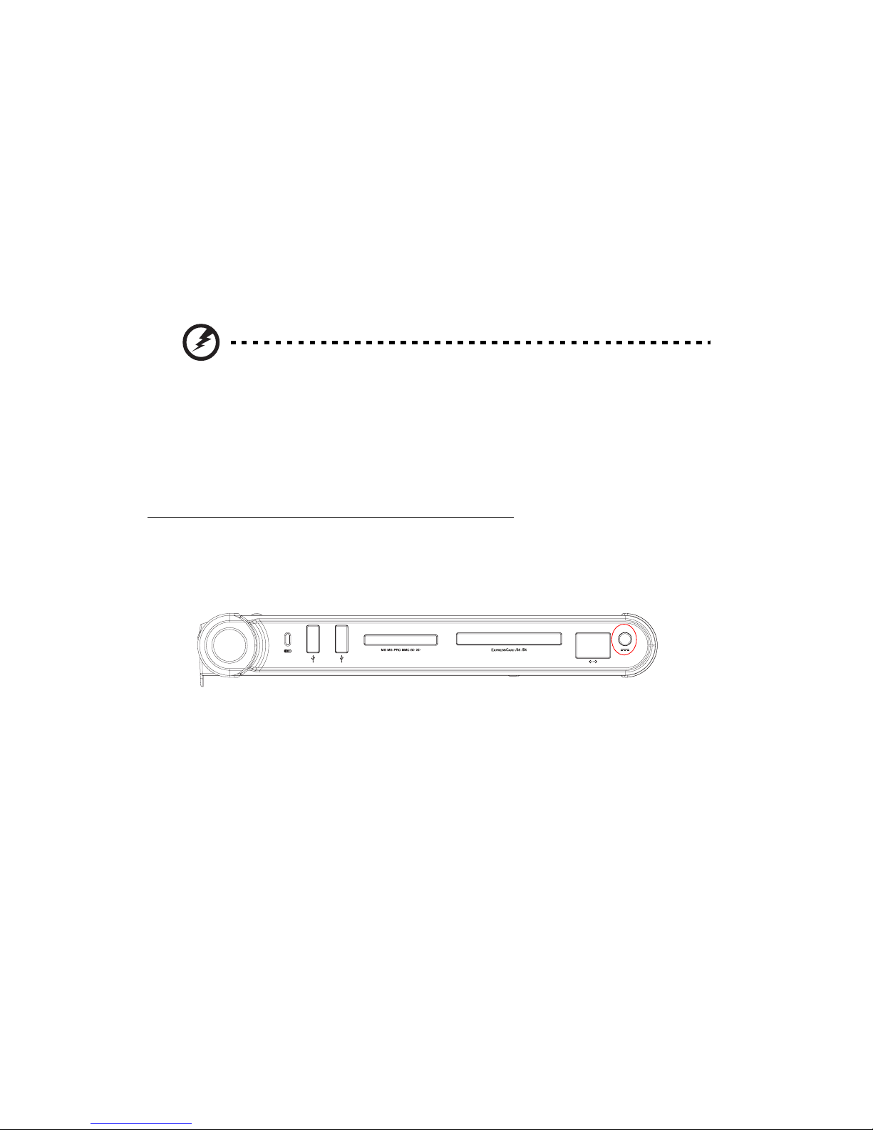
2. Connect one end of the AC adapter to the DC-in port on the docking
station.
3. Connect the power cord to the AC adapter and the other end to a
properly grounded power outlet.
Page 12
To charge the battery in the computer when the computer is
connected to the docking station:
1. Install the battery pack. See page 9 for instructions.
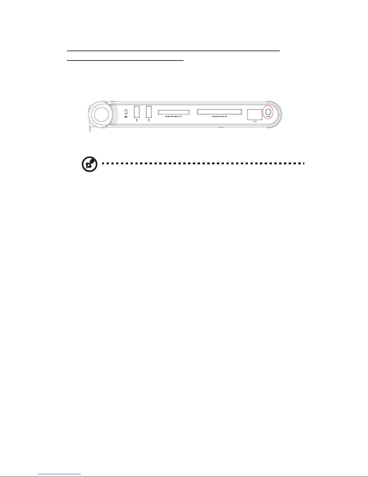
2. Connect one end of the AC adapter to the DC-in port on the docking
station.
3. Connect the computer to the docking station. See page 12 for
instructions.
Note: The docking station charges the battery in the computer first
before it charges the battery in the docking station. However, when
there is no battery in the docking station, you can still use the docking
station to charge the battery in the computer.
11
Page 13
Using the docking station12
Docking the computer
Note: Before you begin, make sure your battery is fully charged and
installed on the docking station.
1. Place the docking station on a flat, stable surface.
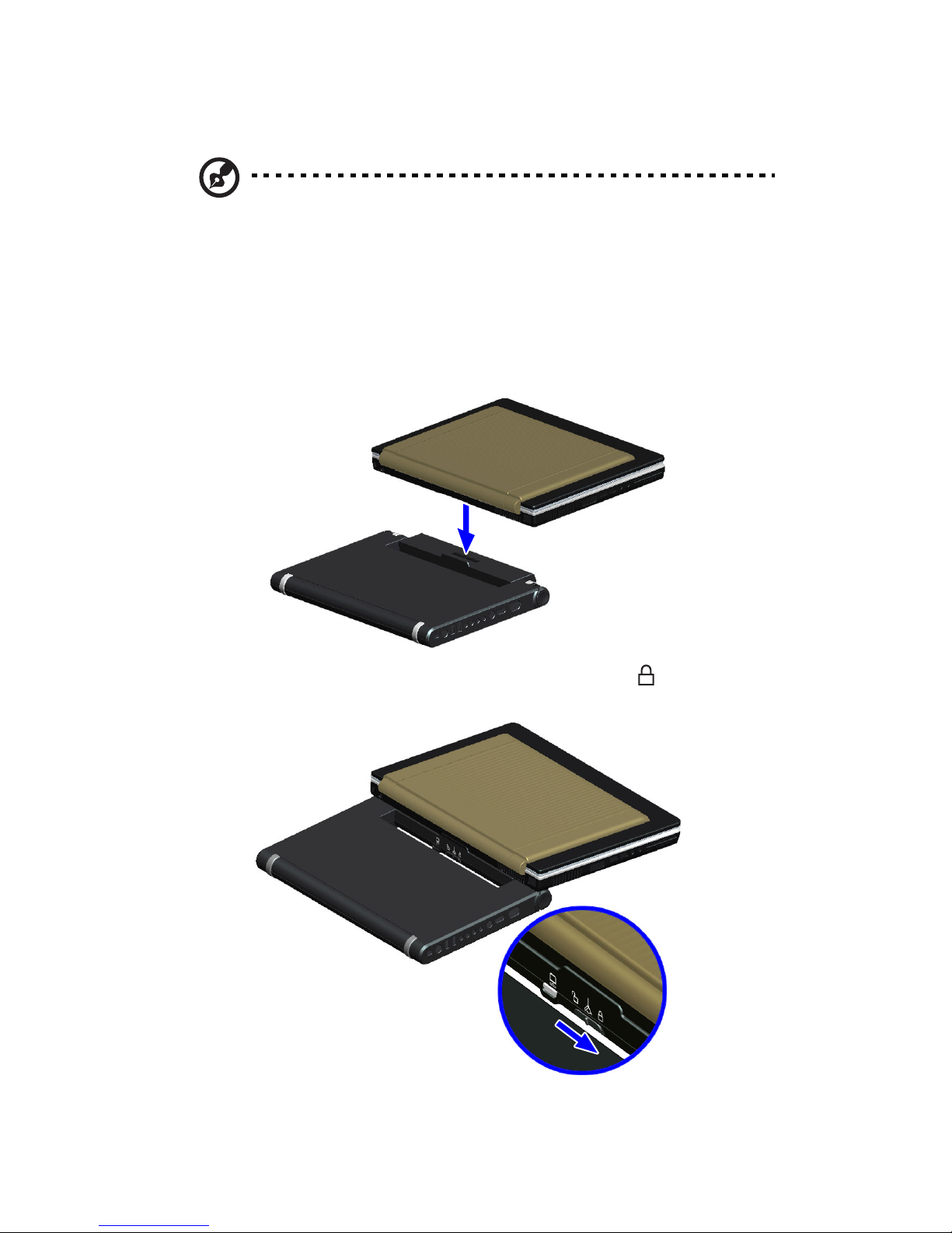
2. Align the docking alignment slots and docking connector on the bottom
of the computer with the alignment pins, restraint brackets, and
docking connectors on the docking station, then gently push down the
computer.
3. Slide the docking rotation latch towards the lock icon to secure the
computer to the docking station
.
Page 14
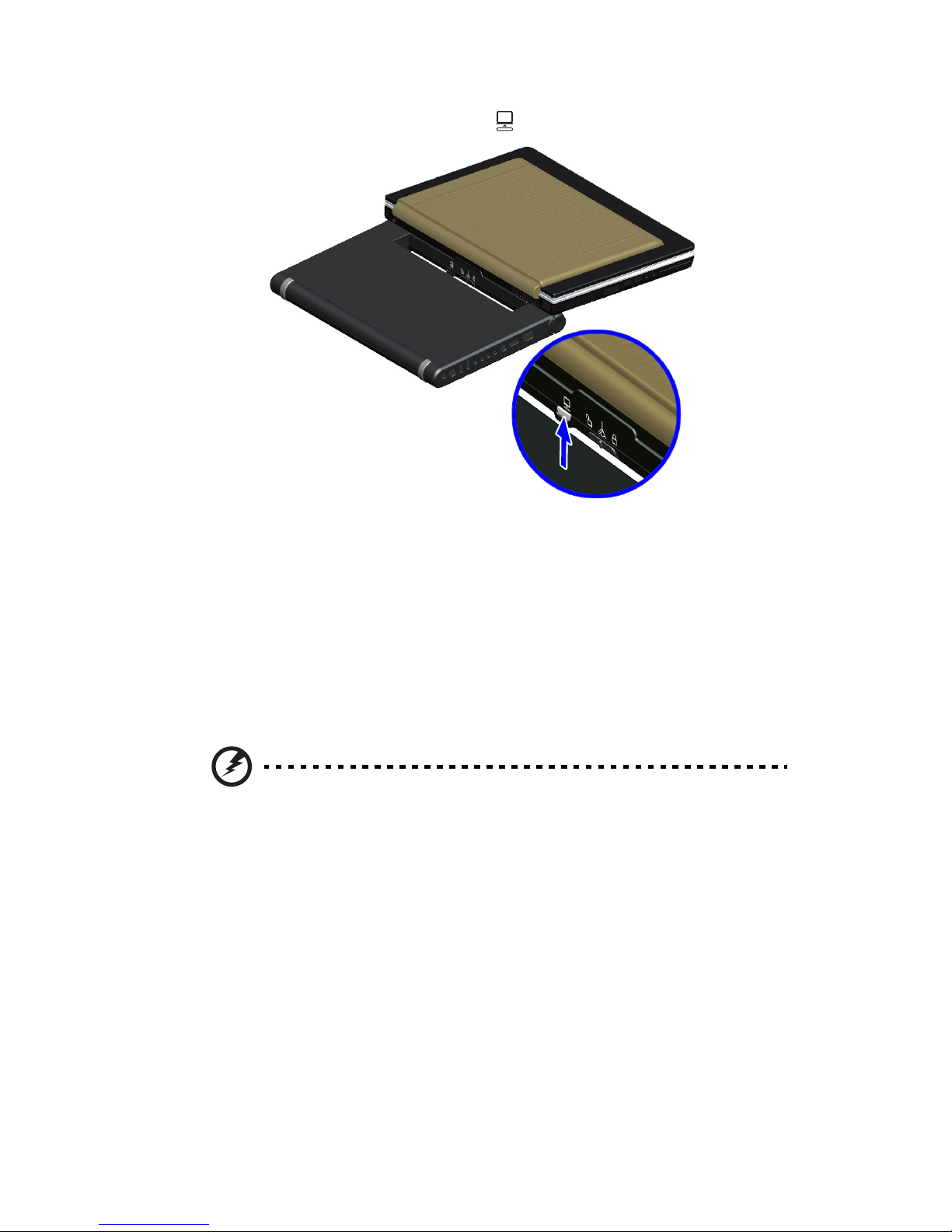
4. Slide the application release latch upward.
13
5. Turn on the computer
The docking indicator on the dreamcom10 notebook computer turns
on. Refer to the dreamcom 10 series Notebook User Guide for the
location of the indicator.
.
Turning the system on
1. Open the display by lifting up the cover then tilt it to a comfortable
viewing position.
Warning! Do not open the LCD display to more than 120° angle
when the computer is positioned at an angle of 10° to the
surface. Failure to do so may cause unit to tip over or fall and
cause serious injury.
2. Press the power button to turn on the power.
Refer to the user manual for more information on how to operate the
computer.
Turning the system off
Follow the standard shutdown procedure described in the user manual.
Page 15
Using the docking station14
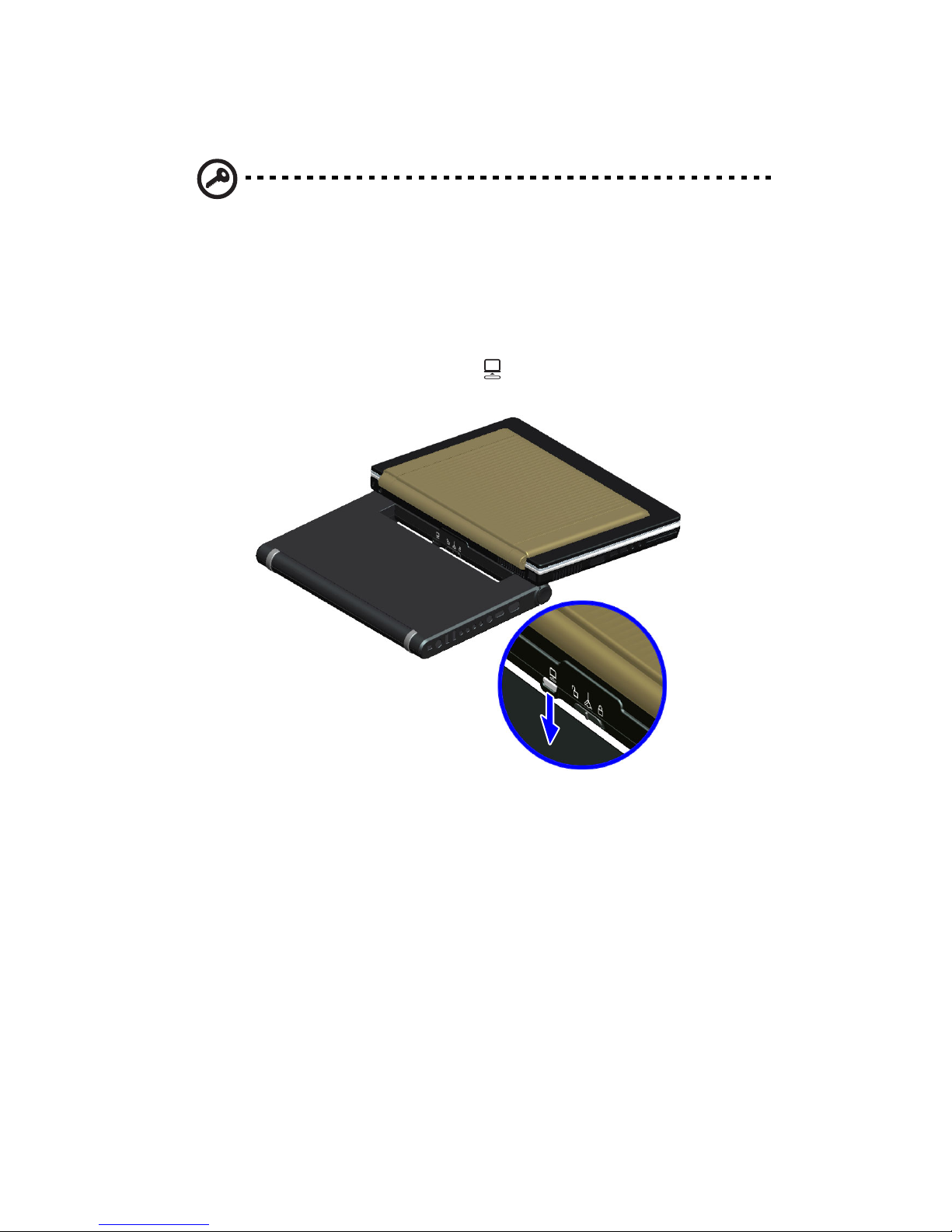
Undocking the computer
Important: When the docking indicator on the dreamcom 10 is on,
you cannot detach your computer with the left and righ eject buttons.
You can request the operating system to undock your computer from
the docking station by sliding the application release latch upward.
1. Make sure that all external peripheral devices connected to the
docking station are not in use.
2. Slide the application release latch down to request the operating
system to undock the computer.
3. Turn the system off.
Page 16
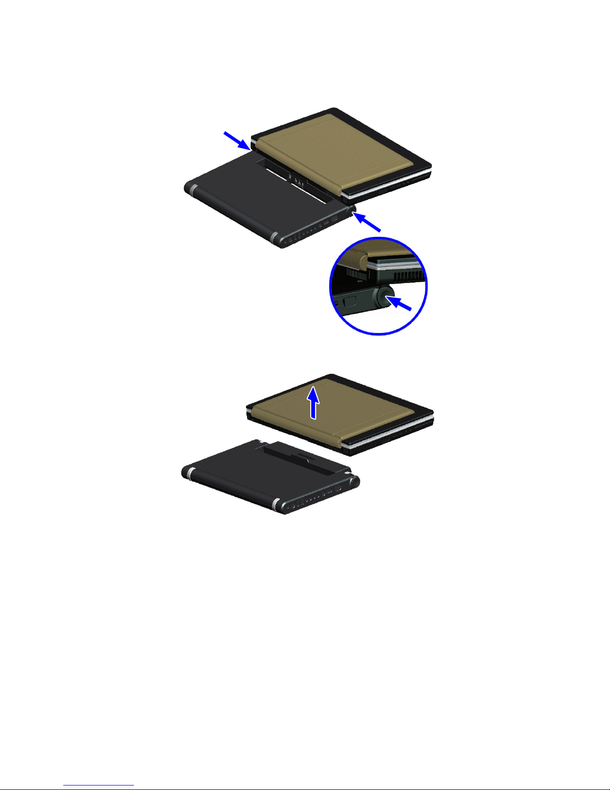
4. Simultaneously press the left and right eject buttons on the docking
station.
15
5. Grasping both sides, lift the computer away from the docking station.
Page 17
Adjusting the computer position16
Adjusting the computer position
The docking station’s rotating handle offers comfortable viewing and angle
adjustment. You can adjust the position of the docking station and
computer in three convenient position adjustment: 0°, 80°, and 174°.
Note: The computer must be connected to the docking station before
performing the below steps. Refer to “Docking the computer” on page
12 for detailed instruction.
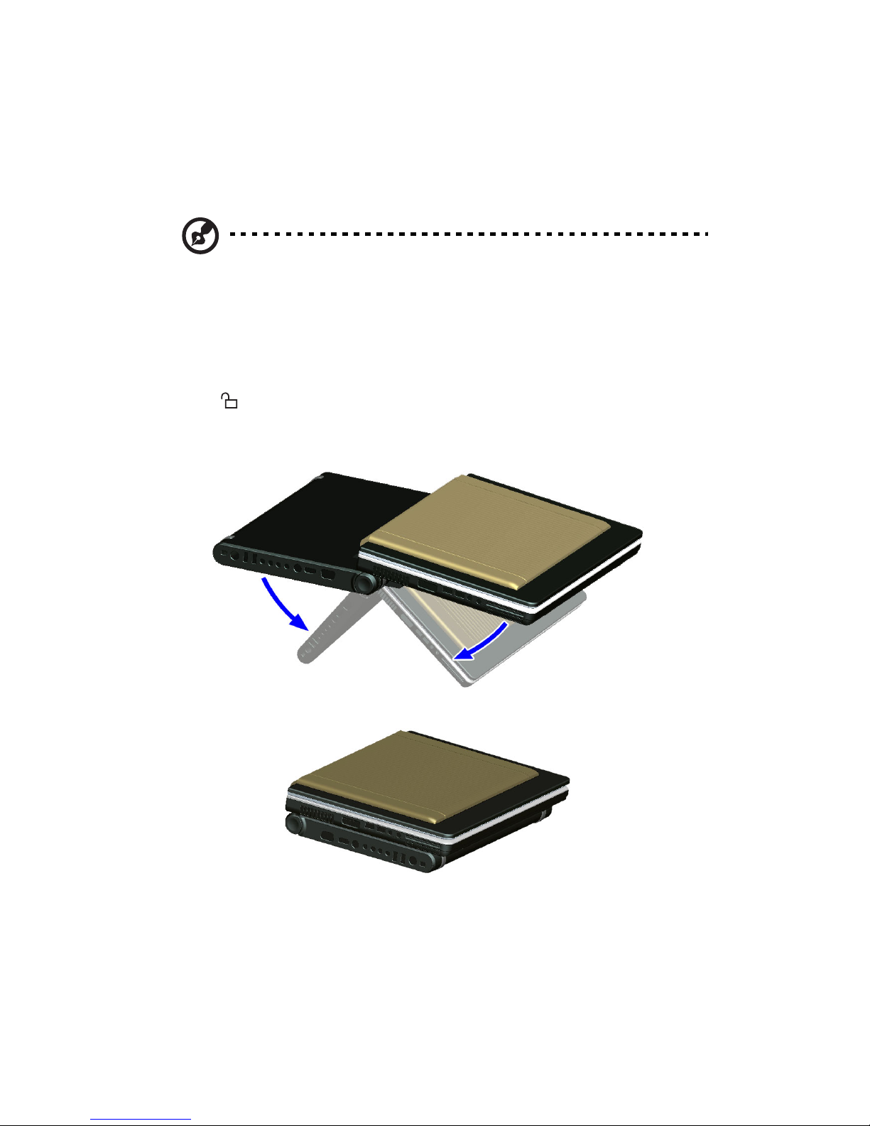
To adjust from 174° to 0° angle:
1. Make sure the docking rotation latch is positioned to the unlock
icon .
2. Lift the computer and docking station assembly, then fold both the
computer and docking station toward the center until they meet.
Page 18
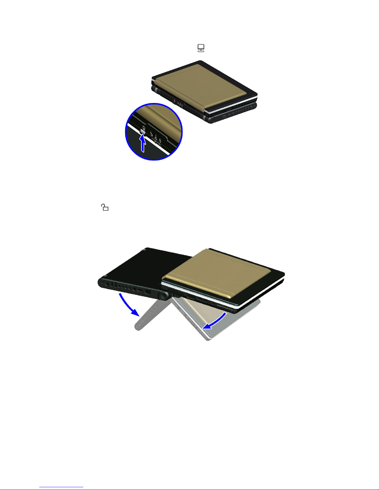
3. Slide the application release latch upward.
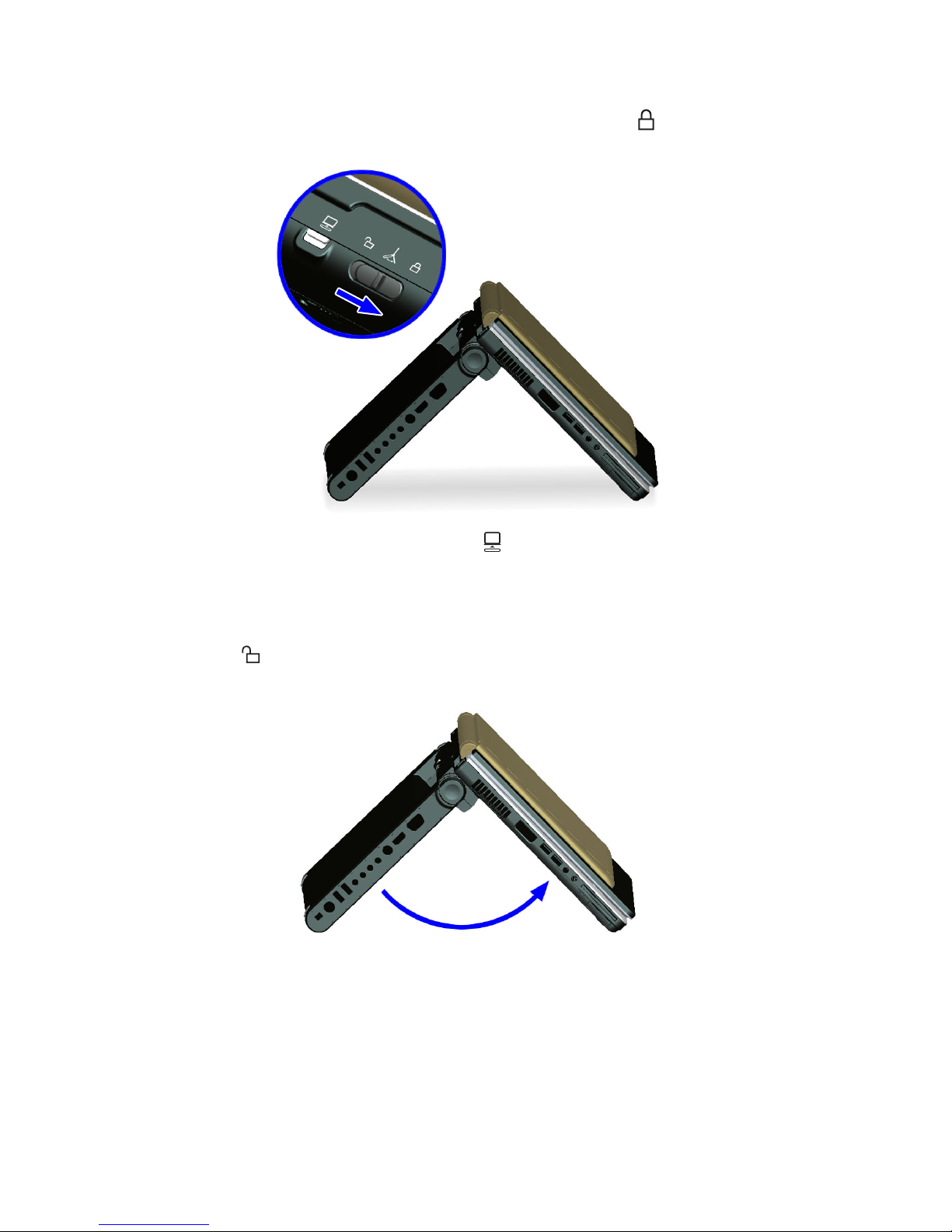
To adjust the computer from 174° to 80° angle:
1. Make sure the docking rotation latch is positioned to the unlock
icon .
17
2. Lift the computer and docking station assembly, then fold the computer
and docking station at 80° angle, as shown in the illustration below.
There is an audible sound when the position is locked.
Page 19
Adjusting the computer position18
3. Slide the docking rotation latch towards the lock icon to secure the
computer and docking station in the locked position.
4. Slide the application release latch upward.
To adjust the computer from 80° to 0°:
1. Make sure the docking rotation latch is positioned to the unlock
icon .
2. Fold in the docking station to the computer.
Page 20
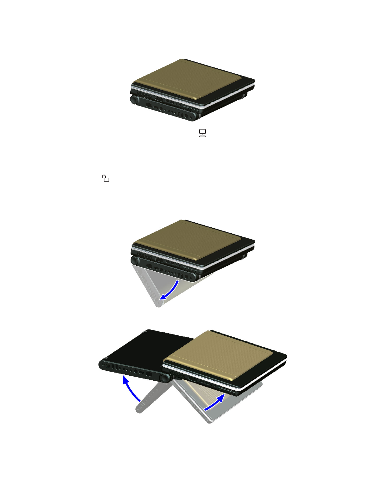
3. Slide the application release latch upward.
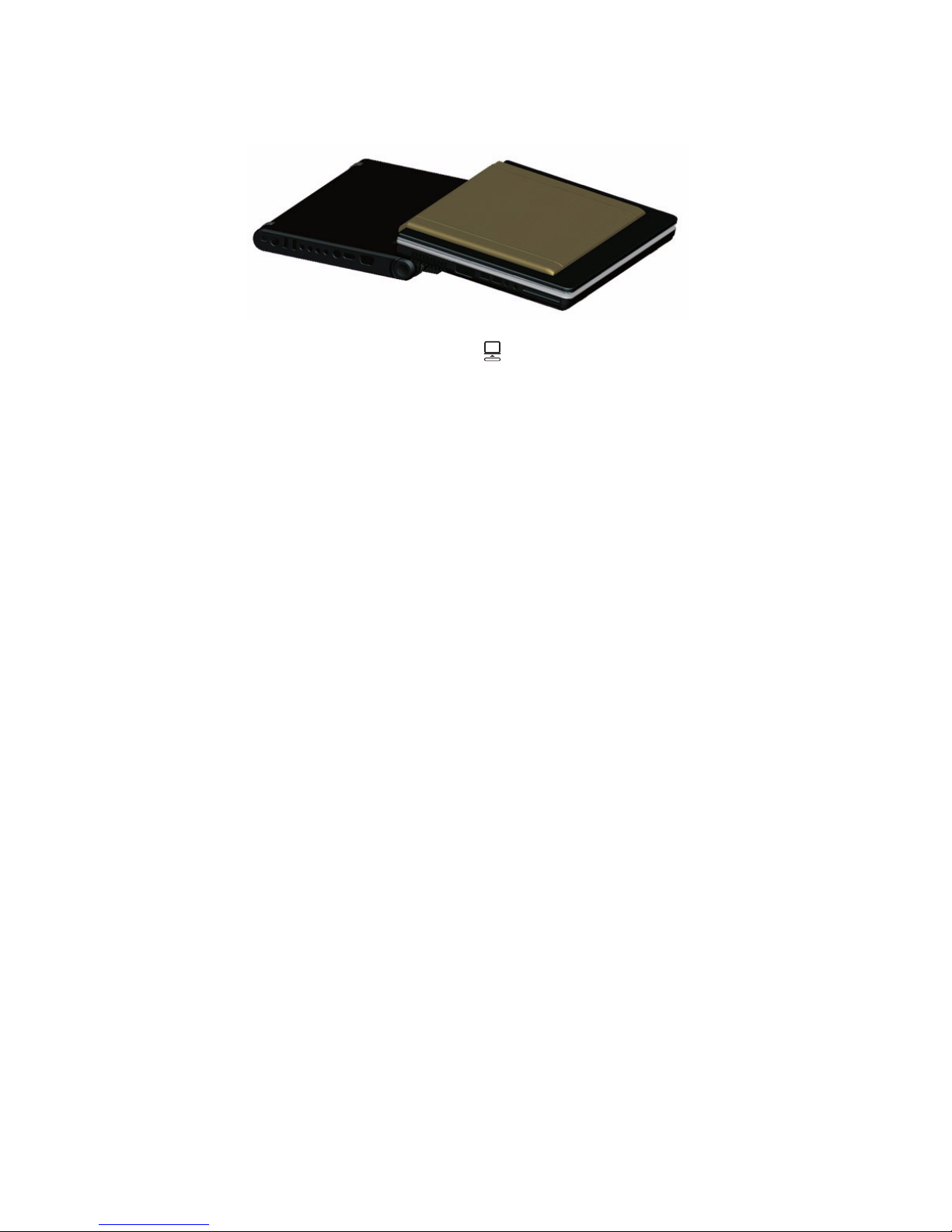
To adjust the computer from 0° to 174°:
1. Make sure the docking rotation latch is positioned to the unlock
icon .
2. Grasp the sides of the docking station and computer and gently pull
the docking station away from the computer until it has reached an
angular position of 174°, as shown in the illustrations below.
19
Page 21
Adjusting the computer position20
3. Slide the application release latch upward.
Page 22

21
Connecting peripherals
This section describes how to connect peripherals and hardware options
that help you use your docking station with ease. When connecting
peripherals, read the manual included with the peripheral for operating
instructions. You can purchase most of these and other options directly
from authorized dealers.
USB devices
The four USB (Universal Serial Bus) 2.0 ports on the docking station allow
you to connect peripherals without occupying too many resources.
Common USB devices include a mouse, keyboard, and digital camera.
Before disconnecting a USB device from your computer, click on the Safely
Remove Hardware icon on the Windows taskbar and click on the device.
When the device can be safely removed, disconnect the device from the
computer. See your peripheral's documentation for details.
External monitor
You can connect an external monitor to the VGA and/or S-video port.
VGA
Connect an external monitor to the VGA port on the right panel. Read the
monitor manual for additional instructions.
Note: If an external monitor is not connected, closing the display
cover puts the computer into Standby mode.
S-video
The S-video port on the docking station allows you to output to a television
or display devices that support S-video input. This is useful if you want to
do some presentations or watch movies on a bigger screen.
External keyboard
If you feel more comfortable using a desktop keyboard, you can connect a
USB external keyboard to an available USB port.
Page 23

Connecting peripherals22
External pointing device
This computer accepts a USB mouse or a similar pointing device. Simply
plug it into an available USB port.
Printer
You can connect a USB printer to an available USB port. See your printer
manual for operating instructions.
Audio devices
Audio devices are easy to connect to the audio ports accessible on the
right panel. You can plug an external microphone (or an audio line-in
device) into the line-in jack. Amplified speakers or headphones connect to
the headphone-out jack. The line-in and line-out jack on the docking
station also supports digital audio devices (S/PDIF).
Video devices
You can connect a DVD player that has a digital interface to the HDMI port.
See your DVD player manual for operating instructions.
ExpressCard
The docking station has a built-in ExpressCard slot that can accommodate
one ExpressCard 34/54 module. Please consult your dealer for
ExpressCard options available that you can purchase for your computer.
Note: Refer to your card’s manual for details on how to install and use
the card and its functions.
To insert an ExpressCard:
1. Hold the card label-side up with the card facing the computer.
2. Slide the card into the slot until it is seated.
Page 24

23
To remove an ExpressCard:
Before ejecting a card:
• Exit the application using the card.
• Left-click on the Safely Remove Hardware icon on the Windows
taskbar and stop the card operation.
1. Gently press the ExpressCard module further into the ExpressCard
slot to pop it out.
2. Pull out the ExpressCard module from the ExpressCard slot.
MultiMedia cards
Your docking station comes with a MultiMedia card slot. This slot is useful
for transferring data to and from a Memory Stick, Memory Stick-Pro, SD,
xD-Picture Card or MultiMedia Card (MMC). Memory cards are used in a
variety of digital devices such as digital cameras, digital camcorders and
mobile phones.
Note: Refer to your card’s manual for details on how to install and use
the card and its functions.
To insert a card:
1. Hold the card with the label facing up and aligned with the slot.
2. Slide the card into the slot until it is seated.
3. The card now appears on My Computer as a removable storage
device that you can copy files to and from.
To remove a card:
1. Make sure no operation (e.g., file copying or deletion) is using the
card.
2. Gently press the card module further into the slot to pop it out.
3. Pull out the card from the slot.
Page 25
Connecting peripherals24
IEEE 1394 devices
The fast IEEE 1394 (4-pin) port on the docking station allows you to
connect IEEE 1394 supported devices like a digital video camera or
external storage devices.
Before disconnecting an IEEE 1394 device, click on the Safely Remove
Hardware icon on the Windows taskbar and click on the device. When the
device can be safely removed, disconnect the device from the computer.
See your peripheral's documentation for details.
TV signal source (not supported in business
version)
The docking station supports analog and digital signal source connection
options.
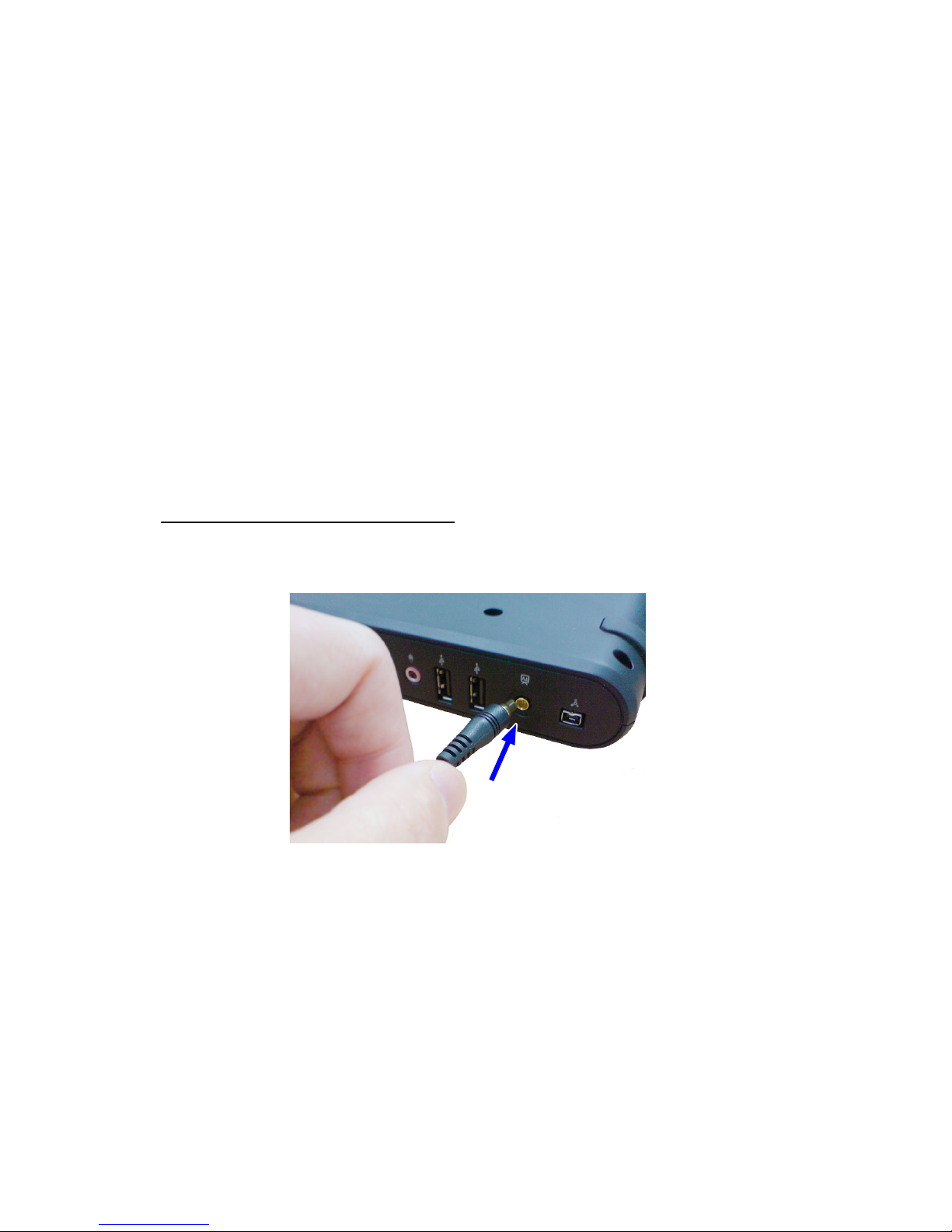
To connect an analog TV signal:
1. Connect the antenna cable adapter to the TV input jack on the docking
station.
2. Connect the other end of the cable adapter to a coaxial cable from a
cable box or cable wall outlet.
Page 26
25
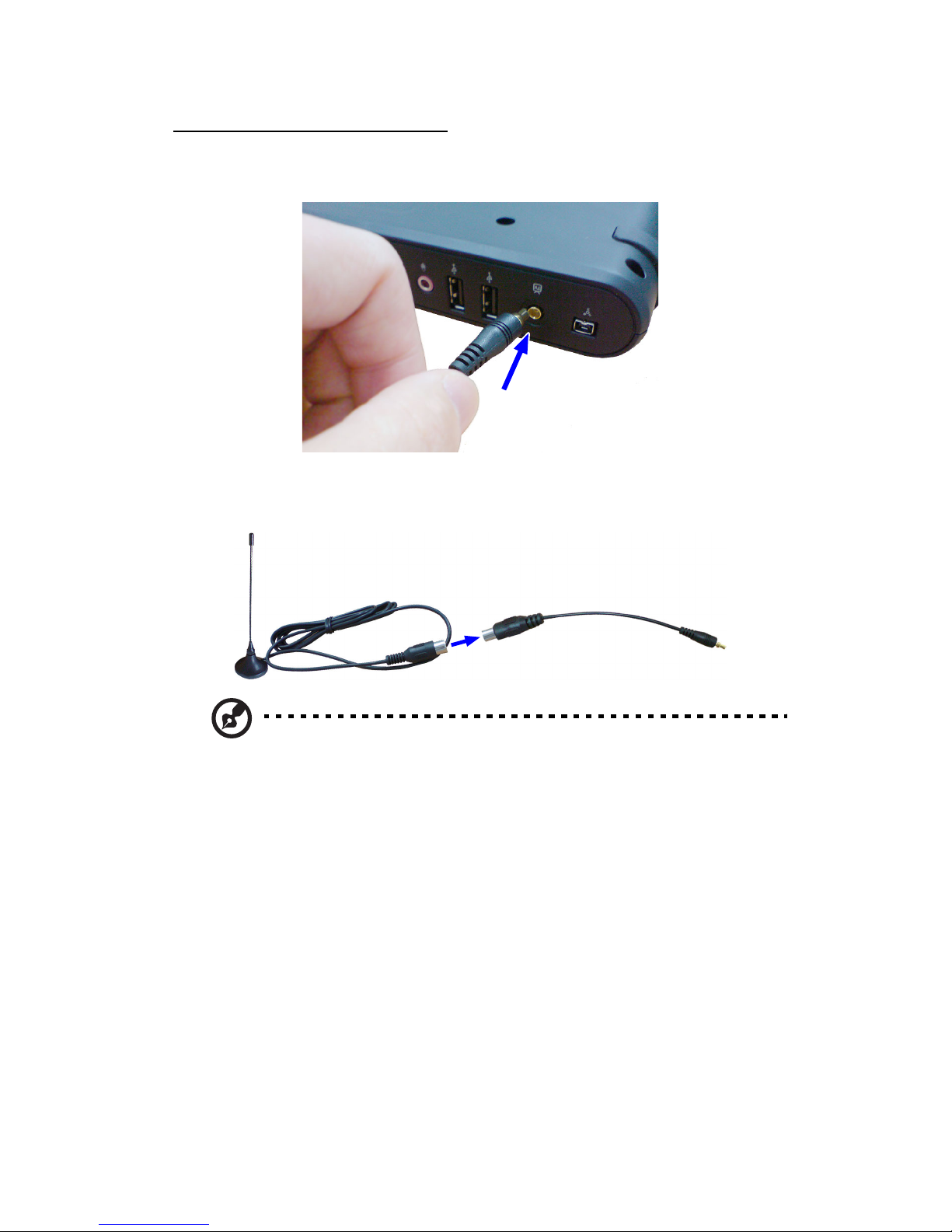
To connect a digital TV signal:
1. Connect the DVB-T cable adapter to the TV input jack on the docking
station.
2. Connect the DVB-T digital TV antenna to the other end of the cable
adapter.
Note: Refer to the manual provided with the DVB-T digital TV
antenna for details on its functions.
Page 27

Replacing the hard disk drive module26
Replacing the hard disk drive module
Tool requirements
We recommend that you have the following tools ready:
• Phillips screwdriver (#00, #0, or #1)
• Plastic flathead screwdriver
ESD (Electrostatic Discharge) precautions
Always observe the following precautions before you replace the SATA
hard drive:
• Do not remove a component from its protective packaging until you are
ready to install it.
• Wear a wrist grounding strap and attach it to a metal part of the
computer before handling components. If a wrist strap is not available,
maintain contact with the computer throughout any procedure
requiring ESD protection.
• Keep the work area free of nonconductive materials, such as ordinary
plastic assembly aids and foam packing.
To replace a hard disk drive module:
Note: Before performing any hardware upgrade, protect your data by
backing up your existing hard disk drive (HDD) before installing a new
hard drive.
1. Turn the unit over.
Page 28
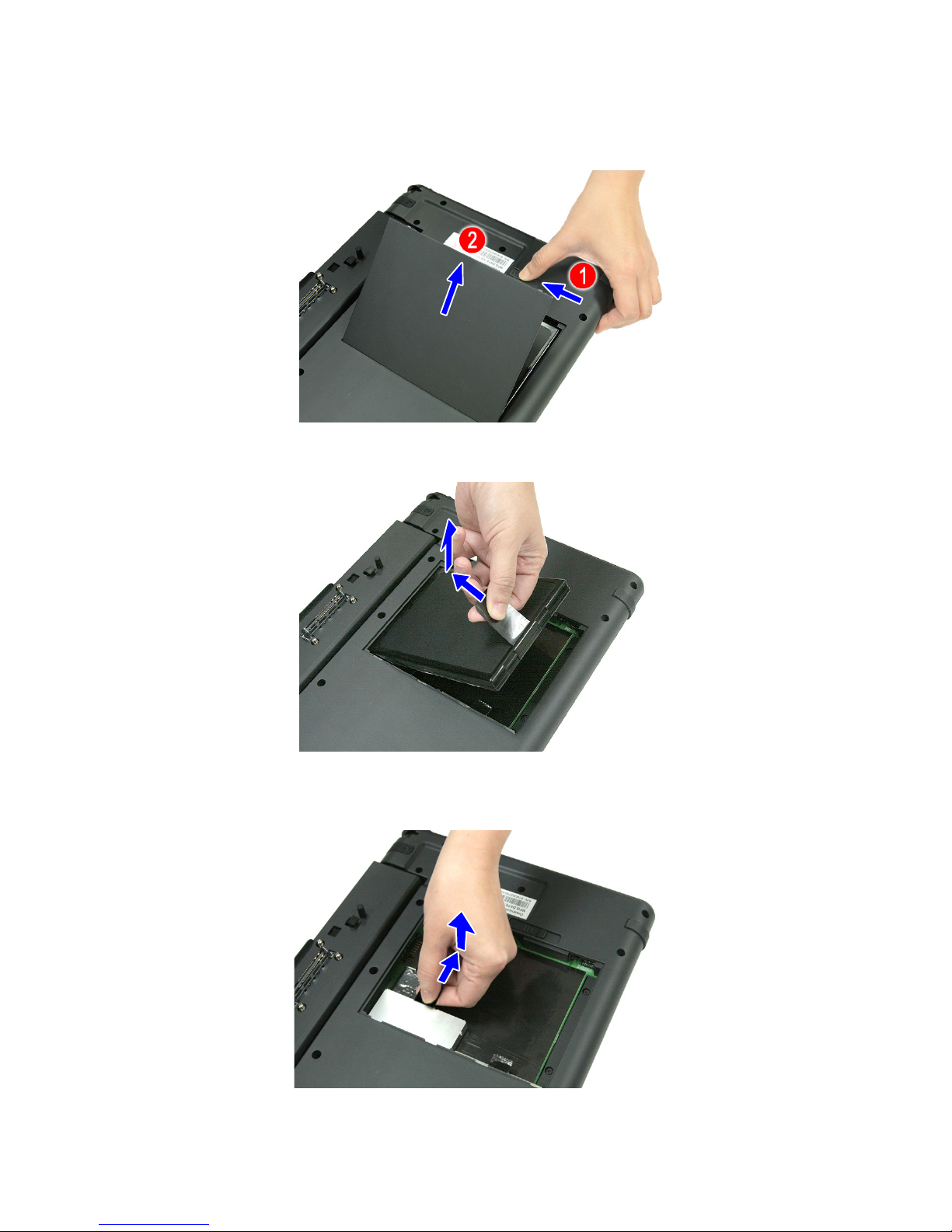
2. Slide the battery cover latch to the left (1), then remove the battery
cover (2).
3. Gently pull on the tape attached to the battery and lift the battery out.
27
4. Gently pull on the tape attached to the HDD module to slide it out of its
bay.
Page 29
Replacing the hard disk drive module28
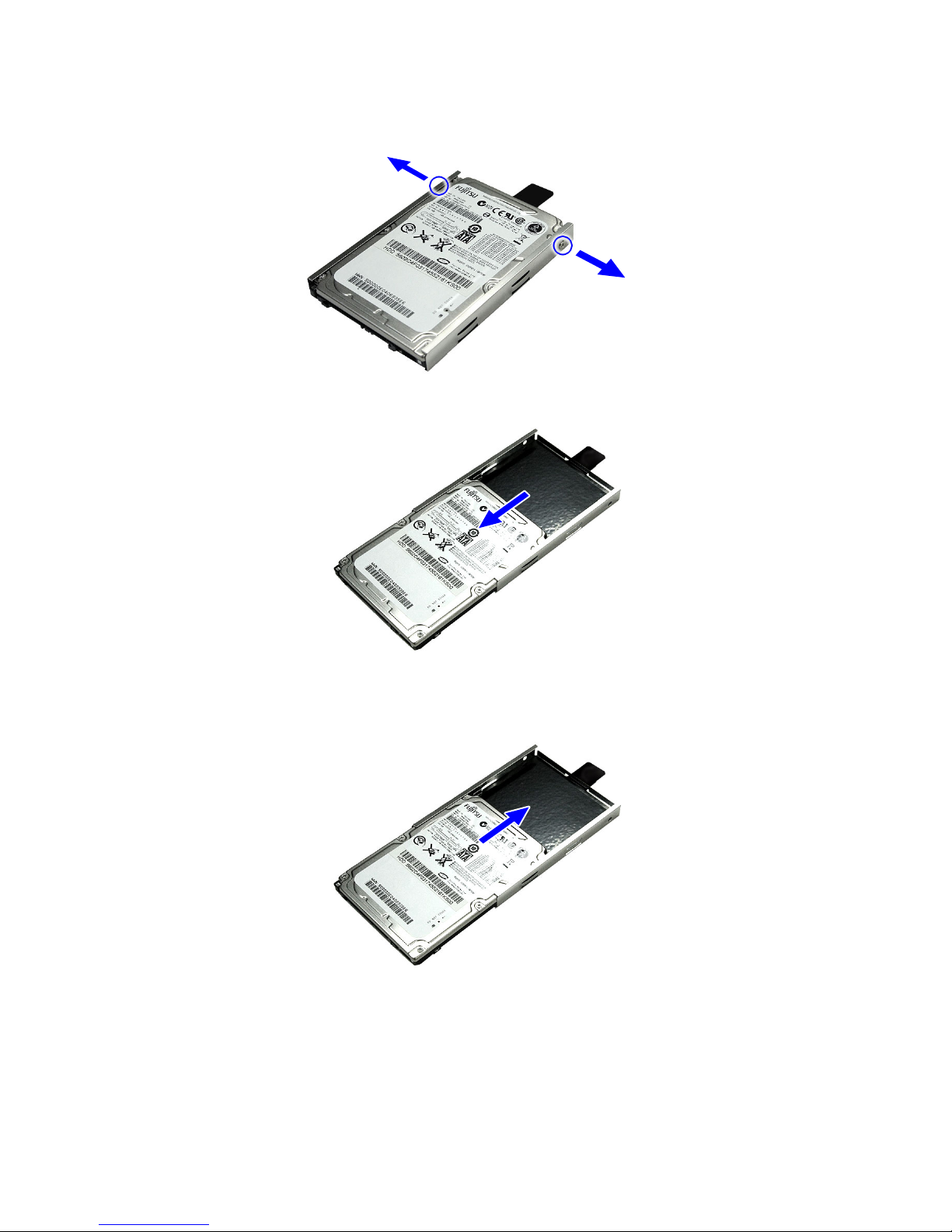
5. Remove the two screws that secure the HDD to the bracket.
6. Slide the HDD out of the bracket.
7. Remove the new HDD from its protective packaging.
8. Slide the new HDD into the bracket.
Page 30
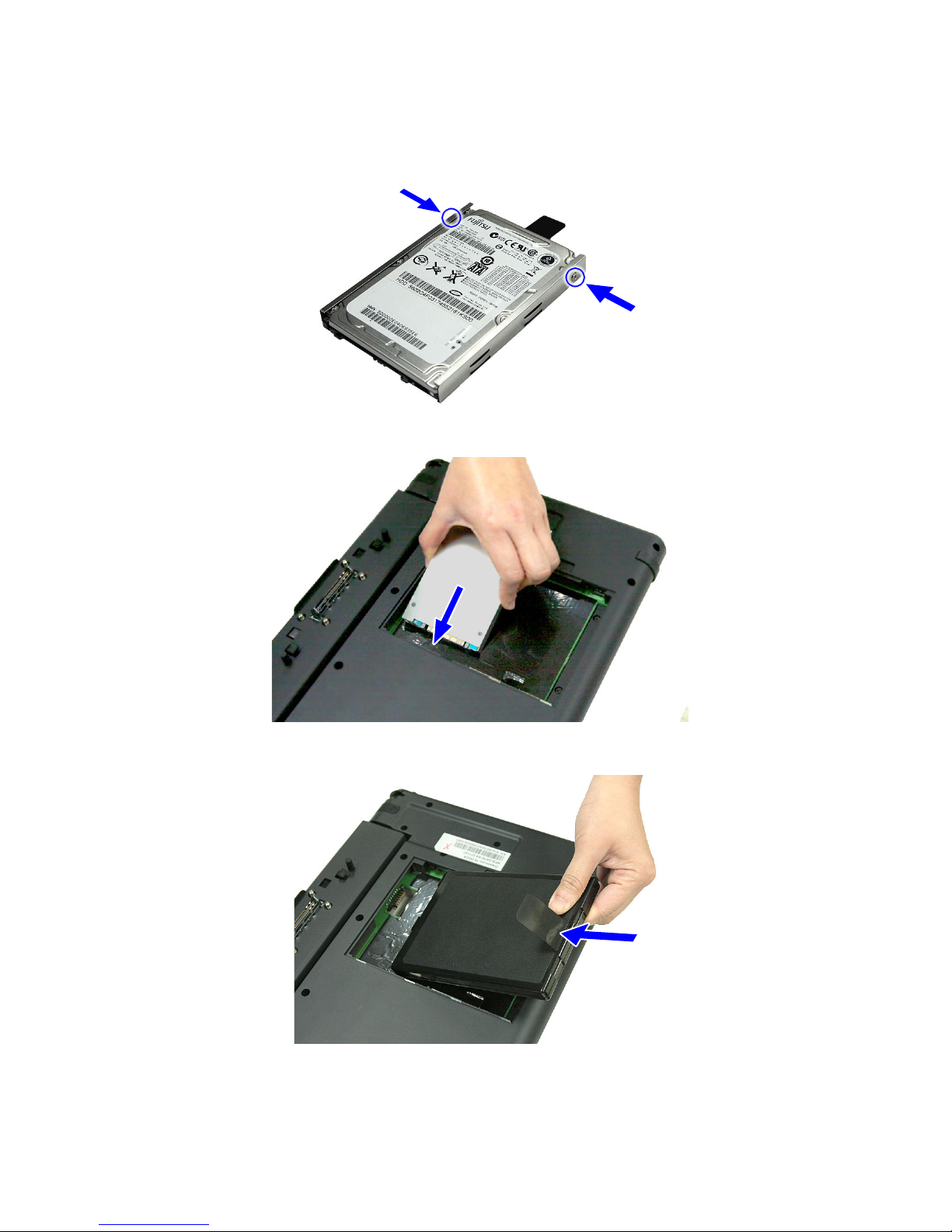
9. Secure the HDD to the bracket with the two screws you removed
earlier.
10. Slide the HDD module into the bay until it is fully seated.
29
11. Replace the battery pack.
12. Replace the battery cover. Make sure to slide the battery cover latch
forward to lock the battery cover.
Page 31

Specifications
I/O ports IEEE 1394 port (4-pin)
TV input jack
Four USB 2.0 ports
Audio line-out jack (S/PDIF) (3.5mm mini-jack)
Audio line-in jack (S/PDIF) (3.5mm mini-jack)
S-video output port
HDMI
VGA
DC-in jack
RJ-45 network jack (Ethernet 10/100)
ExpressCard slot (ExpressCard 34/54 module)
MultiMedia card slot (Secure Digital, Memory
Stick, Memory Stick-Pro, xD-Picture Card or
MultiMediaCard)
Specifications30
Position Adjustment 174° / 80° / 0°
Speaker Output 10W (x2 Channels)
Power Voltage 120VAC, 60HZ, 5.5A
Temperature Operating 15 to + 35° C (Hum < 75%)
Storage 10 to + 50° C (Hum < 35%)
Humidity
(Relative)
Dimension Physical 354 x 262 x 34.5 mm
Weight Gross/Net 1.852 kg (with battery pack)
Note: Product specifications are subject to change without notice.
Operating 20 to 80% non-condensing
Storage 20 to 90% non-condensing
Page 32

31
User support
Refer to the following help resources on how to use the docking station:
• This User Guide - For information on operating instructions.
• dreamcom 10 series Notebook User Guide - For information on how to
operate the notebook computer.
• Technical support - Find the support you need for your specific
product. Go to the Dreamcom Web site http://www.dreamcom.ch
.
Page 33

User support32
Page 34

Index
Numerics
1394 devices
connecting 24
33
D
dc-in jack 6
docking
computer 12
docking connector 5
docking rotation latch 8
lock 12
A
adjusting
computer position 16
application release latch 8
audio
connecting externally 22
B
battery
charging 10
removing 27
battery cover
removing 9, 27
battery pack
characteristics 10
installing 9
C
charging
battery 10
computer
docking 12
turning off 13
turning on 13
undocking 14
computer position 16
adjusting from 0° to 174° 19
adjusting from 174° to 0° 16
adjusting from 174° to 80° 17
adjusting from 80° to 0° 18
connections
1394 devices 24
audio 22
keyboard 21
monitor 21
mouse 22
printer 22
S-video 21
tv 24
USB 21
VGA 21
E
eject buttons 5
left 6
right 8
ESD precautions 26
ExpressCard
ejecting 23
inserting 22
ExpressCard 34/54 slot 6
F
features 4
H
hardware tour
bottom view 8
left view 6
right view 7
top view 5
HDD
installing 28
removing 27
replacing 26
I
indicator
charge LED 6
install
battery pack 9
HDD 28
K
keyboard
connecting externally 21
M
Memory card 23
Memory stick 23
monitor
connecting 21
mouse
Page 35

34
connecting externally 22
MultiMedia card
ejecting 23
inserting 23
MultiMedia card slot 6
O
options
ExpressCard 22
P
ports
HDMI port 7
headphone-out jack 7
IEEE1394 port 7
microphone jack 7
network jack 6
S/PDIF line-in jack 7
S/PDIF line-out jack 7
S-video out port 7
TV input jack 7
usb port 6, 7
VGA port 7
printer
connecting 22
R
remove
battery 27
battery cover 9, 27
HDD 27
replace
HDD 26
tools 26
rotating handle 5
S
Secure Digital 23
specifications 30
S-video
connecting 21
T
tv
connecting to analog signal 24
connecting to digital signal 25
U
undocking
computer 14
USB
connecting 21
user support 31
V
VGA
connecting 21
X
xD-Picture card 23
Page 36

Switzerland, 2008
 Loading...