

Page 1
Owner’s Manual
ANALOG SYNTHESIZER
2 Oscillators
12-24dB Dual Filter
2 Function Generators
Extensive Digital Reverb
30 eurorack patch points
in Athens, GR
Page 2

Contents
Introduction ..................................................................... 3
The Oscillators ................................................................ 4
The Filter ......................................................................... 5
The Modulators .............................................................. 5
The Routing .................................................................... 6
The LFO ........................................................................... 9
The Reverb ....................................................................... 9
The Amp / Drone Mode ................................................. 9
Patch Bay ...................................................................... 10
MIDI Interface and DIP Switch ..................................... 11
The Service Mode ........................................................ 12
Limited Warranty .......................................................... 13
Page 3

Nyx V2.0 / Release Date: 07.05.2019
After the warm embrace of the Nyx V1 synthesizer, it was time to follow
the idea hiding behind the Erebus V3. The new version of Nyx synthesizer has adapted to the format of the Erebus V3 and more features have
been added to its arsenal, including:
• 2 Voltage Controlled Oscillators
• White Noise Generator
• Extremely Flexible Dual Filter from simple 12dB/oct Low Pass,
up to 24dB variable width Band Pass
• Multiple Routing Options
• 3 Loopable Envelope Generators
• Drone mode
• Modulated Reverb, ideal for Ambient sounds (new algorithm)
• 30 patch Points
• Auto-Tuning Function
If you have any suggestion or corrections for this manual please send an e-mail to
dimitra@dreadbox-fx.com
3
Page 4
The Oscillators
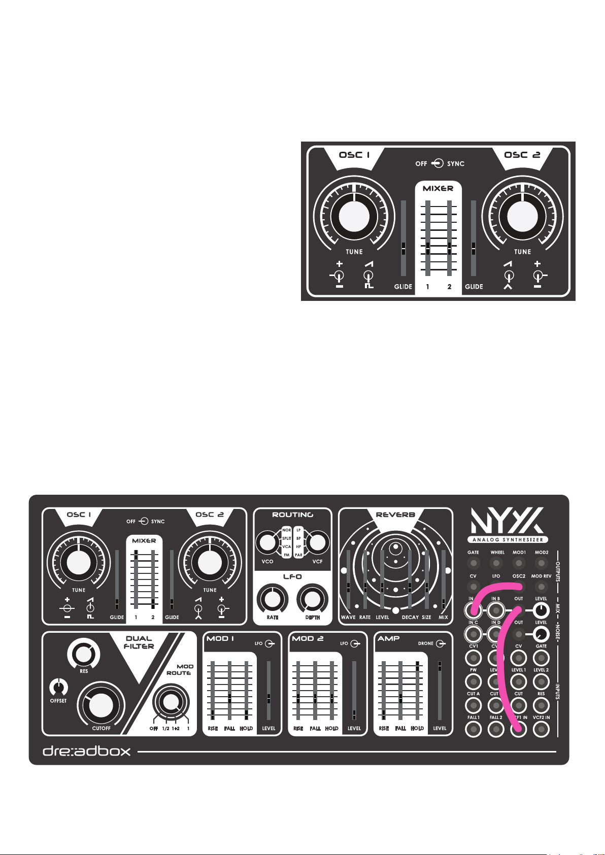
The Nyx v2 is equipped with 2 voltage-controlled, analog oscillators (VCOs). Both OSC 1 and OSC 2
offer identical controls and features, except OSC 2 offers a triangle wave instead of a pulse wave.
We suggest you to use the Nyx v2 with a MIDI interface, as its paraphony and oscillators’ tuning precision heavily relies on MIDI.
OSC 1 and OSC 2 Controls:
1. TUNE knob - allows for precise tuning of each
VCO at ± 12 semi tones.
2. Octave Switch - transpose the VCO pitch over 3
octaves. When using the synth via CV, this should
be left to the middle position, as it is MIDI based
and calculates the autotuning correction.
3. Wave Select Switch - to select either the saw
wave or pulse wave for OSC 1 or the saw wave or
triangle wave for OSC 2.
4. GLIDE slider - allows independent control of the
glide amount for each VCO. This will only work via
MIDI, CV inputs ignore the GLIDE amount
5. MIXER - controls the level of each VCO. Please note that some “negative” amount is allowed, so as to
assist a better CV via the patch points.
6. SYNC - Hard syncs VCO2 to VCO1 pulse. Please note that if VCO2 is at a lower frequency than VCO1,
the effect can often have no result.
How to make an EXTREME DEEP BASS sound. Here is an example you MUST try. Make sure that the
Oscillators are tuned with precision.
4
Page 5
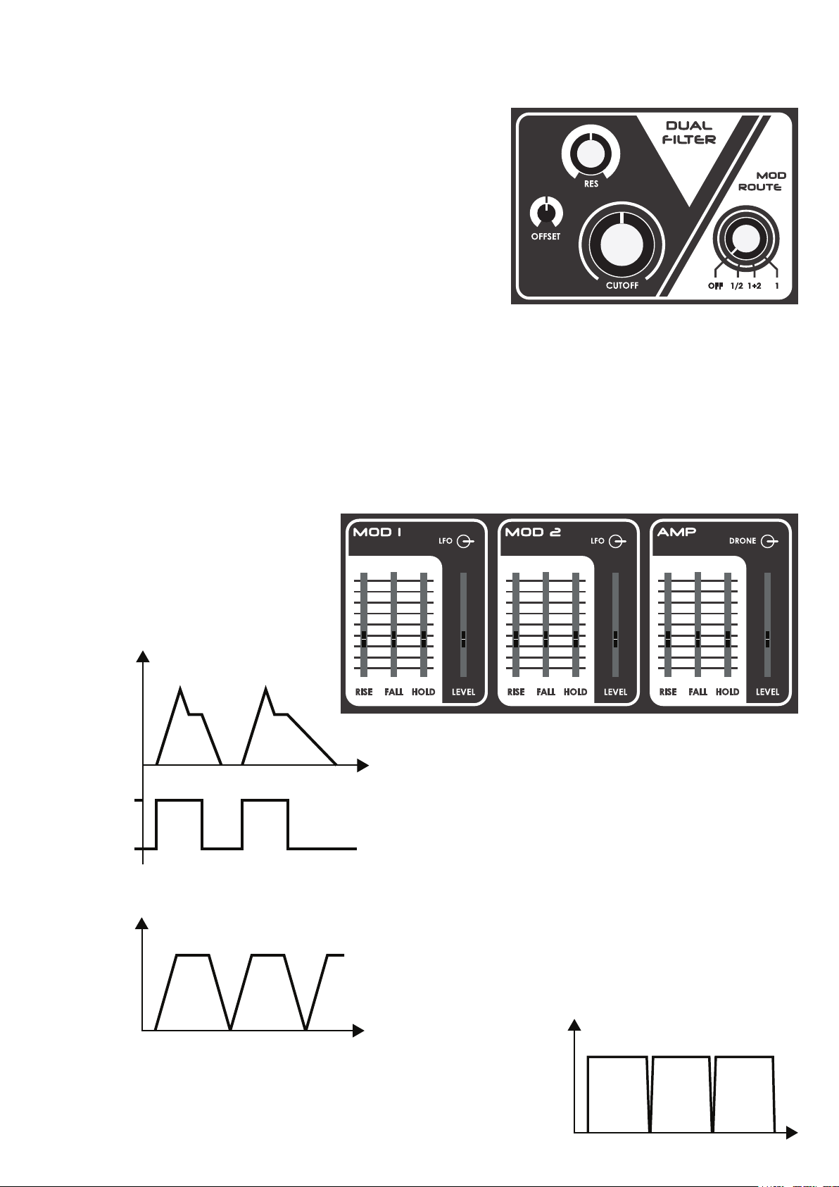
The Dual Filter
Filter Controls:
1. CUTOFF knob - sets the Cutoff frequency of both lters
2. RES knob - controls the amount of resonance (sometimes
referred as Q) to the lter cutoff frequency
3. OFFSET knob - sets the Cutoff difference of the second lter. Normally is set at 50%
4. MOD ROUTE
OFF: No Modulator (MOD) controls the Filter
1/2 : MOD1 controls Filter1
MOD2 controls Filter2
1+2 : Both Modulators control both Filters
1 : Only MOD1 controls the Filter
About the Dual Filter
The Nyx V2 Synthesizer, is equipped with 2 pre-fed Filters, each at 12dB/oct. You can achieve various
Filter combinations, from a Classic 24dB/oct Low Pass or even a variable width Band Pass.
Please refer to the “ROUTING” for more info.
The Modulators
Nyx V2 offers 3 Digital Modulators/
Envelopes. MOD1, MOD2 and the AMP
modulator.
When on Envelope mode, each time a
MIDI note is ON or a Gate is triggered,
the Envelopes will start doing their cycle.
ENVELOPE
LEVEL
NOTE ON
NOTE OFF
When on LFO or Drone (for the AMP) Mode, the Modulators function as Cycling Envelopes.
Rise stands for the Attack time
Fall is the Decay and Realease time
Hold is the Sustain Level
Rise is the rise time
Fall is the fall time
Hold is the time that is left on a high state
Having both Rise and Fall at 0% and Hold at a decent amount, will
result in a constant high, but with short “off” bursts.
5
Page 6

The Routing
The routing section is the most important part of the Nyx v2 synthesizer. Understanding how it works,
is the key to create complex sounds. There are 2 routing controls (+ the MOD Routing, which is explained on the Filter section), VCO and VCF.
Let’s have a look at the following scheme :
LP
VCO1
VCO2 VCF2
You can see the main parts of the synth. These
will be routed now via the routing controls
VCO ROUTE
VCF1
HP
VCA
LP
HP
NOR: Stands for NORMAL. Both VCOs are sent to VCF1.
LP
VCO1
VCF1
HP
VCA
LP
VCO2 VCF2
HP
SPLIT: VCO1 is being sent to VCF1 and VCO2 is being sent to VCF2.
LP
VCO1
VCF1
HP
VCA
LP
VCO2 VCF2
HP
VCA: Both VCOs are being sent directly to the VCA.
LP
VCO1
VCF1
HP
VCA
LP
VCO2 VCF2
HP
6
Page 7

HALF: Both VCOs are being sent to VCF2.
LP
VCO1
VCF1
HP
VCA
LP
VCO2 VCF2
HP
VCF ROUTE
LP: Stands for LOW PASS. Both lters are set to a Low Pass mode and in series.
LP
VCF1
VCF2
HP
LP
HP
x
x
VCA
BP: Stands for BAND PASS. The lters are in series, but VCF1 is on HP mode and VCF2 is on LP mode.
x
LP
VCF1
HP
LP
VCA
VCF2
x
HP
HP: Stands for HIGH PASS. The lters are in series and both are in High Pass mode.
x
LP
VCF1
HP
LP
x
VCA
VCF2
HP
PAR: Stands for PARALLEL. The lters are in Low Pass mode, but they are independant from each other.
LP
VCF1
HP
x
VCA
LP
VCF2
HP
x
7
Page 8

Now combining all the Routing information, we have created a table with the following options.
LP BP HP PAR
NOR
SPLIT
VCA
HALF
24dB/oct
Low Pass
VCO1
24dB/oct
Low Pass
VCO2
12dB/oct
Low Pass
pure VCOs
free lters
24dB/oct
Low Pass
Free resonant
Low Pass
and 12dB/oct
Low Pass
12dB/oct
Band Pass
VCO1
12dB/oct
Band Pass
VCO2
12dB/oct
Low Pass
pure VCOs
free lters
12dB/oct
Band Pass
Free resonant
High Pass
and 12dB/oct
Low Pass
24dB/oct
High Pass
VCO1
24dB/oct
High Pass
VCO2
12dB/oct
High Pass
pure VCOs
free lters
24dB/oct
High Pass
Free resonant
High Pass
and 12dB/oct
High Pass
12dB/oct
Low Pass
VCF2 is free
VCO1
12dB/oct
Low Pass
VCO2
12dB/oct
Low Pass
pure VCOs
2x free lters
12dB/oct
Low Pass
Free resonant
Low Pass
and 12dB/oct
Low Pass
If you combine all the above with the Modulation Routing options, you can have a wide range of combinations.
For example:
VCO -> SPLIT
VCF -> PAR
MOD -> 1/2
You have each VCO with its own lter and independent modulator.
8
Page 9

The LFO
Nyx V2 has a simple but effective LFO, which was designed mostly for pitch vi-
brato sounds.
LFO Controls:
1. RATE knob - sets the LFO cycle rate
2. DEPTH knob - sets the LFO amount
The Reverb
We have developed a new algorithm for the Reverb of the Nyx V2, to accompany drones so as to create
haunted and aetherial soundscapes. The rst three slider controls consist the modulation of the effect
and the last three are the actual reverb controls.
The Modulation of the Reverb, is a random voltage generator, which will
actually create a “movement” on the sound.
Modulation Controls:
1. WAVE slider - smooths the waveform of the modulation
2. RATE slider - sets the frequency of the modulation event
3. LEVEL slider - sets the amount of the modulation
Reverb Controls:
4. FEED slider - sets the decay of the reverb
5. SIZE slider - sets the room size
6. MIX slider - blends between completely dry to wet sound
Please note that overdriving the signal, especially when the FEED is high, will cause the effect to distort.
Also when setting the mix of the oscillators above 70% or applying too much resonance, self oscillation
can distort the signal.
The Amp
In order to control the Nyx V2 VCA, we use the Amp Modulator, which is described in the Modulator
section (p. 5). The Amp Modulator is functioning exactly the same as the others. The difference is that
instead of the LFO mode, we have a DRONE mode, which is exactly the same but named differently for
clarity, as when this is engaged the synthesizer produces sound without having to trigger it via MIDI or
Gate.
Drone Mode
There is another Drone Mode available through setting switches 3,4,5 to the ON position that enables
you to have pitch control over the Oscillators without the use of an external device. Now the GLIDE
sliders of each oscillator transforms to the Coarse Tuning, but the Octave switches and the MIDI note
messages are deactivated. You can still send all the other available MIDI messages.
9
Page 10

The Patch Bay
The Nyx V2 has 30 patch points, offering endless routing and modulation possibilities.
The Patch Bay is consisted of 4 major parts:
GENERAL OUTPUTS
1. GATE : outputs the gate CV (0-6.5V pulse)
2. WHEEL : outputs the modulation wheel CV (0-5V)
3. MOD1 : outputs the Modulator 1 CV (0-5V)
4. MOD2 : outputs the Modulator 2 CV (0-5V)
5. CV : outputs the MIDI notes to CV (0-10V) over 10 octaves
6. LFO : Direct output of the LFO. When patching this, the effect on
the pitch of the oscillators will be cancelled. (+/- 3V)
7. OSC2 : outputs the selected wave of the OSC2 (+/- 5V)
8. MOD REV : outputs Reverb Modulation CV. Always at max level
(+/- 5V)
MIX
9-12. IN A, IN B, IN C, IN D : mixer inputs (+/- 10V max)
13. OUT: outputs the sum of IN A, IN B, IN C, IN D
LEVEL : sets the level of the mixer’s output (+/- 10V max)
NOISE
14. OUT : white noise (+/- 5V max)
LEVEL : sets the level of the White Noise
INPUTS
15. CV1 : OSC1 CV input 1V/oct (+/- 2% off to precision) (+/-10V)
16. CV2 : OSC2 CV input 1V/oct (+/- 2% off to precision) (+/-10V)
17. CV : OSC1 and OSC2 CV input 1V/oct (+/- 2% off to precision) (+/-10V)
18. GATE : expects a 0 to 5V pulse so as to handle as a Gate signal. (can accept from 3.3V up to 10V)
19. PW : pulse width control over the square wave of OSC1
20. LEVEL : controls the amplitude of both OSC1 and OSC2 (+/-5V)
21. LEVEL1 : controls the amplitude of OSC1 (+/-5V)
22. LEVEL2 : controls the amplitude of OSC2 (+/-5V)
23. CUT A : controls the Cutoff frequency of Filter1 (+/-5V)
24. CUT B : controls the Cutoff frequency of Filter2 (+/-5V)
25. CUT : controls the Cutoff frequency of both Filter1 and Filter2 (+/-5V)
26. RES : controls the amount of the resonance (+/-5V)
27. FALL1 : controls the fall rate of the MOD1(+/-5V)
28. FALL2 : controls the fall rate of the MOD2(+/-5V)
29. VCF1 IN : audio input on VCF1
30. VCF2 IN : audio input on VCF2
10
Page 11

The MIDI Interface and DIP Switch
The Nyx V2 has a relatively simple MIDI interface, as it is an improvisation synthesizer, patch bay use
is needed so as to get the most out of it.
Both MIDI IN and MIDI THRU jacks can translate MIDI input as described in the table below. Please
note that MIDI THRU will not transfer the MIDI ground. This is needed for some gear in order to work
properly. If that is the case, avoid using the MIDI THRU.
Also, the MIDI THRU can be used to send a second MIDI device to control the Nyx V2 at the same time.
Here is the complete list that the MIDI interface will handle:
- Note tracking
- Gate on/off
- Pitch wheel
- Mod wheel
- Channels from OMNI up to 6th.
MIDI CHANNELS
In order to change the MIDI channel, just use the DIP switch located on the back panel of the Nyx V2.
For the MIDI selection, we use DIP 3,4, and 5.
OMNI 3,4,5 off
CH1 5 on
CH2 4 on
CH3 4,5 on
CH4 3 on
CH5 3,5 on
CH6 3,4 on
UNISON / PARAPHONIC MODE
Nyx V2 is a Paraphonic synthesizer, but it can also be used in standard Unison (mono) mode. In order
to change between the 2 modes, use the DIP switch 2 on the back panel. By default when 2 is off, Paraphonic mode is enabled.
When in paraphonic mode, by hitting a single key all VCOs will follow this note, but by hitting a second
at the same time, it will have OSC 1 playing the low note (Low note priority), and OSC 2 playing the last
note (Last note priority). In paraphonic mode, envelopes are always on retrigger mode. Normally, when
releasing 2 pressed notes, all sources will follow the note last pressed.
In Unison mode, only one note will follow. Every time a new note is pressed, the oscillators will track this
one (Last note priority). Envelopes on this mode are always without retrigger.
AUTOTUNING
When DIP 1 is On, the background autotuning is active. This means that whenever the AMP envelope
is at a rest, (the release stage must have ended!) the autotuning will kick in, after 1 second. This will
calibrate the scaling of the oscillators, so as they are constantly in tune. Each calibration takes about
10-15 seconds and it will run in an endless loop. After just 1 calibration, the unit is ready to play, but it
is strongly suggested that you allow the synth to warm up for at least 5 minutes before playing. When
powering up the unit an auto tune calibration will start and this will “lock” your synthesizer from all Gate
and MIDI signals for about 30 seconds.
You can deactivate this by setting DIP 1 to off position. This will force the unit to make a single autotune - regardless the AMP state. For example, have OSC 1 on, set the lter to a wide open state and the
sustain and release of the AMP at max. Press a key and immediately turn the DIP 1 off. This will do a
single audible autotuning process.
The only reason to set the DIP 1 to the off position, is the need to use the synthesizer for modular purposes with other gear, as when the AMP is low, the OSCs will be calibrated and they will shift in octaves.
11
Page 12

This might be a rare occassion and most of the times you will want the DIP 1 set to on. Nontheless, if
you have to do it, let the unit warm up for 20 minutes, and then you can turn the DIP 1 off, with con-
dence that the Oscillators are in tune.
AUTOTUNING TROUBLESHOOT
The Oscillators cannot stay in tune:
Make sure that the synthesizer is not affected by any heating elements (a/c, radiator, etc.) and that it is
generally in a temperature stable environment. Have in mind that the Nyx V2 is an analog synthesizer
with the pros and cons that comes with it. Also check that the DIP1 is ON or that before setting it to the
OFF position, the unit has been warmed up, as described above.
I can hear the Autotuning on the background:
It has been observed that the Nyx V2, sometimes, when it is connected to other devices that add a gain
element to its output and not directly to a monitor, may create a ground loop. This will cause the Autotuning procedure to be audible at about -70dB. You can negate this, by setting the Nyx V2 AMP level at
max and control the volume of the synthesizer from the connected device. Additionally, you can allow
the unit to warm up for 20 minutes and then set the DIP1 to the OFF position.
DIP switch / Pin’s description
1 : Auto- tuning ON/OFF
2 : Paraphonic / Unison
3 : Midi Channel
4 : Midi Channel
5 : Midi Channel
6 : Service Mode
3+4+5 : Drone Mode
Service Mode / Fine Tuning Procedure
In order to tune the Nyx V2 synthesizer, a MIDI keyboard, a pair of speakers and a tuner is needed. Con-
nect everything and turn the unit on for at least 30 minutes on Autotune Mode (DIP1 ON).
1. Set both Tune potentiometers to center position (50%)
2. Set VCO routing at VCA
3. Set all modulations, modulators, lter and effects at 0%.
4. Set VCA HOLD and LEVEL to 100%.
5. Turn on the DIP 6 and restart the synth by toggling the power switch. A LED will start blinking under OSC2 Tune.
6. Toggle 5 times the Drone switch of the AMP and the LED will make a fast ashing sequence and then
becomes stable. Toggle 5 times more this switch and the LED will start ashing fast. After 30 seconds
or more the ashing speed will be decreased. The synth now is ready to start the auto-tune procedure.
On this mode Glide sliders are repurposed as netune controls.
7. Turn OSC1 level to 100% from the mixer.
8. On the MIDI keyboard press and hold A0 and with the Glide slider set the tune to match that note.
9. Set OSC2 level to 100% and set the glide slider to that note so no beating occurs.
10. Set OSC2 level to 0% and let the key.
11. Repeat steps (8,9,10) for A1, A2, A3, A4, A5 and A6 respectively.
12. When A6 is tuned turn DIP6 to off position and restart the synth.
ATTENTION!
Each time you release a key, for example if you press A2 and then release it, it will automatically store
your current Glide (FineTune) settings for both oscillators for the octave C0-C7. Be careful so as not to
accidentally hit any other key than the ones noted in the procedure above. If you do so you must repeat
the whole process from the beginning. Be sure to follow it exactly as described.
12
Page 13

Firmware Update
In order to upgrade the Firmware of the Nyx V2 Synthesizer, you will need to follow the instructions of
the .zip le, which you can download from www.dreadbox-fx.com/nyx2
Then connect a MIDI cable from your MIDI device to the unit’s MIDI IN port, Turn the DIP switch 6 to the
ON position and power on your unit. A LED below OSC2 Tune Potentiometer will start blinking. Toggle
enough times the MOD1 LFO switch so that the LED will stop blinking and stay lit.
Limited Warranty
Dreadbox warrants this product to be free of defects in materials or construction for one year from
the date of purchase. Proof of purchase is necessary when the warranty claim is made. Malfunctions
resulting from improper power supply voltages, backward or faulty cable connection, abuse of the
product or any other causes determined by Dreadbox to be the fault of the user, are not covered by its
warranty (normal service rates will be applied). All defective products will be replaced or repaired at
the discretion of Dreadbox. Products must be returned directly to Dreadbox with the customer paying
the shipping costs. Dreadbox implies and accepts no responsibility for harm to a person or apparatus
through the operation of this product.
Please contact support@dreadbox-fx.com for the return to manufacturer authorization, or for any other technical questions or concerns.
Kindly note that the wooden sides and the screen printing are done by hand, which means that natural
differences or imperfections are normal and expected.
WARNING!
Do not open the unit
Use a Dust cover
Turn off the synthesizer when you are not using it
Keep the original packaging
13
Page 14

PRESET : ...........................................................
Notes :
 Loading...