

DRE Waveline Plus Service Manual
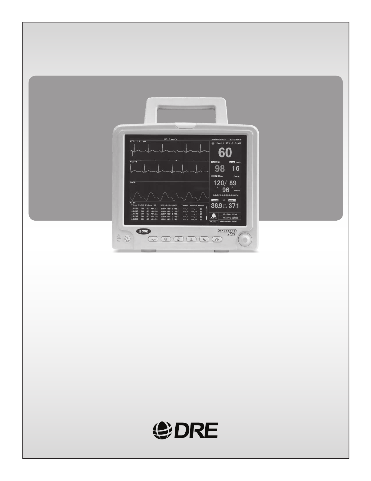
DRE Waveline Plus
Service Manual

TABLE OF CONTENTS
SECTION 1 General Introduction.............................................................. 1-1
A. About the Manual.........................................................................1-1
B. Safety Information........................................................................1-1
C. Service Information......................................................................1-3
SECTION 2 Device Introduction................................................................ 2-1
A. Product Description......................................................................2-1
B. Front Panel ...................................................................................2-1
C. Rear Panel.....................................................................................2-3
D. Side Panels ...................................................................................2-4
E. Technical Specification................................................................2-4
F. Requirements................................................................................2-8
SECTION 3 Maintenance and Calibration.................................................. 3-1
A. Maintenance Schedule..................................................................3-1
B. Manufacturer Responsibility ........................................................3-1
C. Visual Inspection..........................................................................3-1
D. Cleaning........................................................................................3-2
E. Thorough Inspection and NIBP Calibration.................................3-2
F. Electricity Safety Test ..................................................................3-5
SECTION 4 Troubleshooting..................................................................... 4-1
SECTION 5 Assembly demonstration ...................................................... 5-1
SECTION 6 Technical Drawings................................................................ 6-1
A. System Configuration ..................................................................6-1
B. Schematic Drawing ......................................................................6-1
C. PCB Component Layout and Test Points.....................................6-1
SECTION 7 Spare Parts List...................................................................... 7-1
DRE, Inc.
www.dremed.com

Section 1 General Introduction
A. About The Service Manual
1. Objective: The Service manual is mainly used by biomedical equipment technicians and
service personnel. Users shall have sufficient electronic technology background, including analog
and digital electronics as well as computer technology.
2. Scope: A qualified professional may take this manual as a reference in the monitor installation,
maintenance and service.
3. Main Contents: The manual consists of the following chapters:
Chapter 1 General Introduction: Introduces the users, applications, main contents, safety and
service information of the manual.
Chapter 2 Device Introduction: Describes the product, networking Service specifications,
preparations before use and operation principles.
Chapter 3 Maintenance: Includes making maintenance plan, visual inspection, cleaning, check
and test.
Chapter 4 Troubleshooting: Introduces the monitor structure and system defaults setting.
Chapter 5 Disassembly demonstration: Provides assembly procedure.
Chapter 6 Technical drawings: Provides technical diagram.
Chapter 7 Spare parts list: Provides spare parts list.
B. Safety
1. Manufacturer Responsibility
The Company shall be responsible for the safety, reliability and performances of the monitor
under the following conditions:
Installation, operation, function upgrade, readjustments, modifications and service are
conducted by professional authorized by the Company.
Electric installation with neighboring rooms are conducted in accordance with the requirements
of correct rules.
The equipment is used correctly in conformity with operation guidance.
2. Precautions
B/0 1-1
The user of the monitor must be qualified persons who have been trained and are capable of
using the monitor correctly.
To protect patients’ safety, use only parts and accessories manufactured or recommended by the
Company.
Before connect the equipment to any other equipment not recommended in the manual, please
contact the Company in advance.
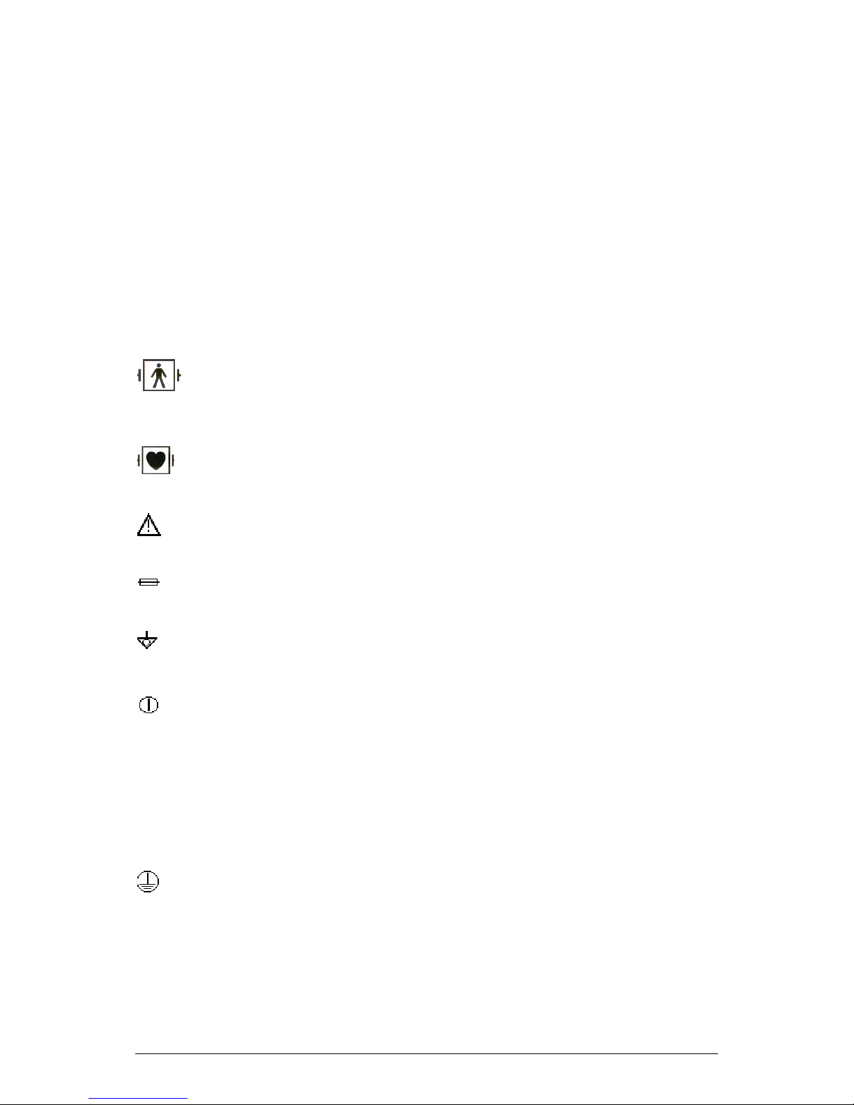
3. External Marks of the Equipment
Note: As the parameter configuration of the monitors can be different, there may not be some
marks on the monitor you purchased.
Defibrillator protection BF type applied part: F type applied part (float/insulation),
complies with IEC-60601-1 particular requirements, with higher requirements for
electric shock protection than B type applied part.
Defibrillator protection CF type applied part: F type applied part (float/insulation),
complies with IEC60601-1 particular requirements, with higher requirements for electric
shock protection than BF type applied part:
Caution: Check accompanying documents.
Fuse.
Electric potential balance terminal.
Power on /off (press-press)
CE
0123
The product is in conformity with the requirements of MDD 93/42/EEC through
certification by TUV P.S.
~
Alternating Current.
Protective Earth (Ground)
4. Classification
In accordance with IEC 60601-1 standards, UT4000F monitor and its applied parts are classified
as follows:
B/0 1-2

Classified according to type of electric shock protection: Class I, with internal power supply.
Classified according to degree of electric shoc k prote cti o n: BF type applied part – N I BP, SpO2,
Temperature. CF type applied part – ECG, Respiration, invasive blood pressure.
Classified according to degree of harmful liquid prote cti on: com mon equipment (enclosed
equipment without protection against liquid going in).
Classified according to the safety degree when used in environment of mixed gas of
combustible anesthetic gases and air or /and mixed gas of oxygen and N2O: the equipment
cannot be used in environment with mixed gas of combustible anesthetic gas and air or mixed
gas of oxygen or N2O.
Classified according to working mode: Continuous running mode.
5. Terminology
The terminology used in the manual “ Warning”, “Caution” and “Note” indicates the hazard and
remind users of the precautions to be taken according to the degree of importance. Hazard
indicates the potential cause which may result in injury to human body.
Warning: indicates the potential hazard or unsafe action which may result in death or serious
injury if not avoided.
Caution: indicates the potential hazard or unsafe action which may result in relatively minor injury
to human body or damage to product if not avoided.
Note: provides useful information and hint reminding user to pay attention to and ensure that the
monitor may play its role to the maximum degree.
C. Service Information
1. Service Requirements
Please observe the following service requirements:
Only refer to the Customer Service Center about the equipment service issues.
Equipment failure due to unauthorized service shall not be warranted.
Monitor shall be maintained regularly according to the service schedule, otherwise, it may result
in equipment failure, even hazard.
During the life time of the equipment, regular maintenance is the essential way to keep the
monitor function normally.
2. Equipment Identification
Each monitor manufactured by the Company has a unique serial number for equipment
identification and service.
B/0 1-3
Section 2 Device Introduction
A. Product Description
The monitor is easy to carry, advanced function, easy to use.
1. Dimension 320mm W x 250mm H x170mm D
2. Weight 7.95 Kg
3. Screen 10.4"
4. Unity Network The device can be linked with central station.
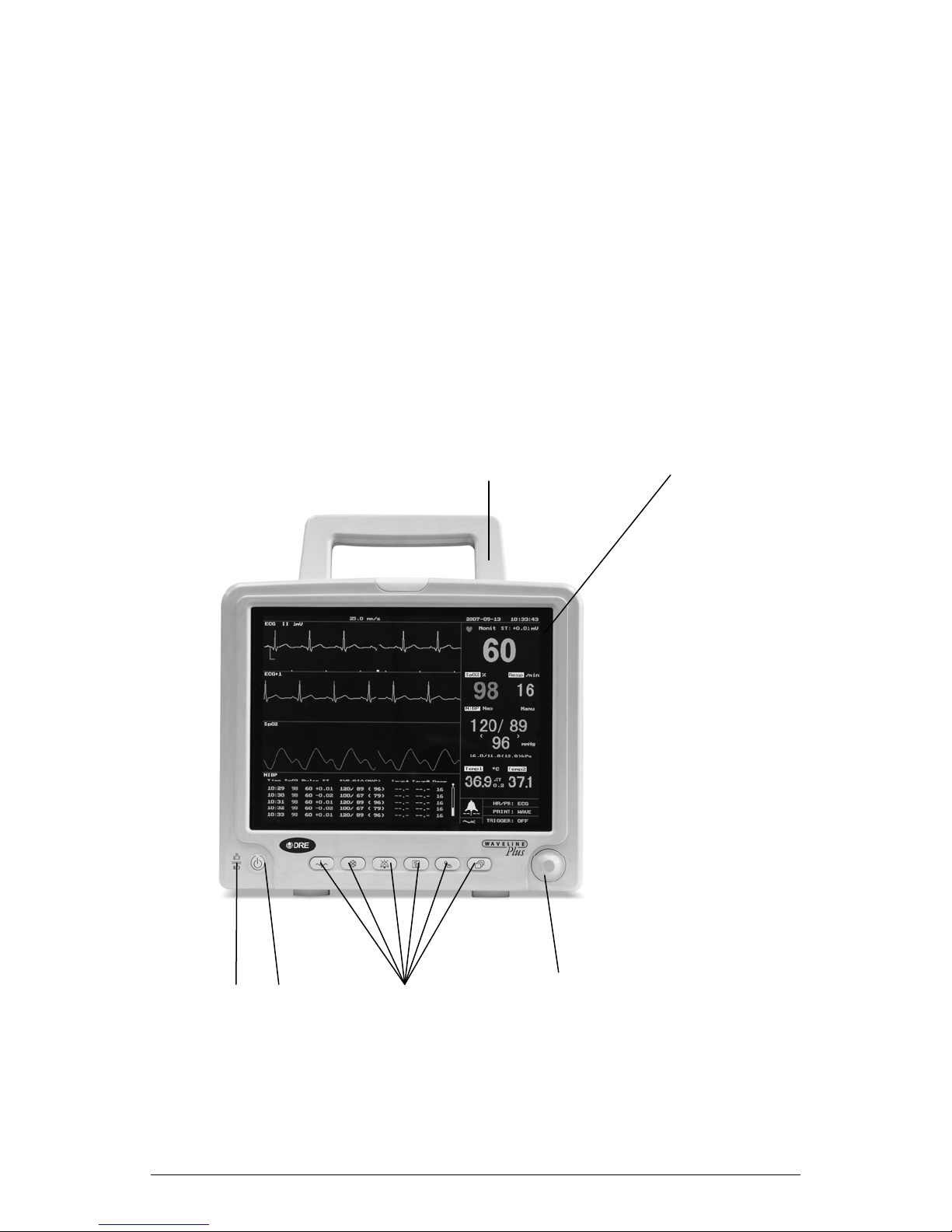
B. Front Panel
The front panel of the Omni multi-parameter patient monitor is as follows:
1 2
3 4 4---9 10
B/0 2-1

(1) Handle
(2) Screen
(3) Power LED
Indicator
(4) Power Switch
(4) ECG Menu
(5) Waveform
Freeze/Restore
(7) Silence
(8) Print
(6) Start/Stop
NIBP Measure
(9) Main Menu
(10) Trim Knob
This handle is convenient for operator to carry the patient
monitor.
TFT screen for displaying waveform, menu, alarm status and
vital sign measurement results.
When the patient monitor is powered on, the LED is in green.
When the patient monitor is connected to AC power supply but
not turned on, the LED is in orange, indicating that the internal
battery is being charged.
Press this key to turn on /off the patient monitor.
Press this key to enter ECG Setup menu.
When a waveform sweep is displayed, press the key to freeze
the waveform.
When a waveform is being frozen, press this key to unfreeze
the waveform and restore waveform sweep.
Press this key to enable or disable Alarm sound.
Press this key to activate the recorder to print. Press this key
again to stop printing.
Press this key to start a blood pressure measurement. If the
patient monitor is in the process of blood pressure
measurement, press this key to stop blood pressure
measurement.
When screen does not display menu bar, press this key to
display the main menu bar. When the screen is displaying main
menu bar, press this key, then the main menu bar will disappear
from the screen.
When menu is displayed, rotate the knob to select the functions
at the bottom of the screen. When mouse cursor (arrow) is
pointing to a certain function, press the knob to select the
function. Then rotate the knob to select the desired item. In the
end, press the knob again to confirm the selection.
B/0 2-2
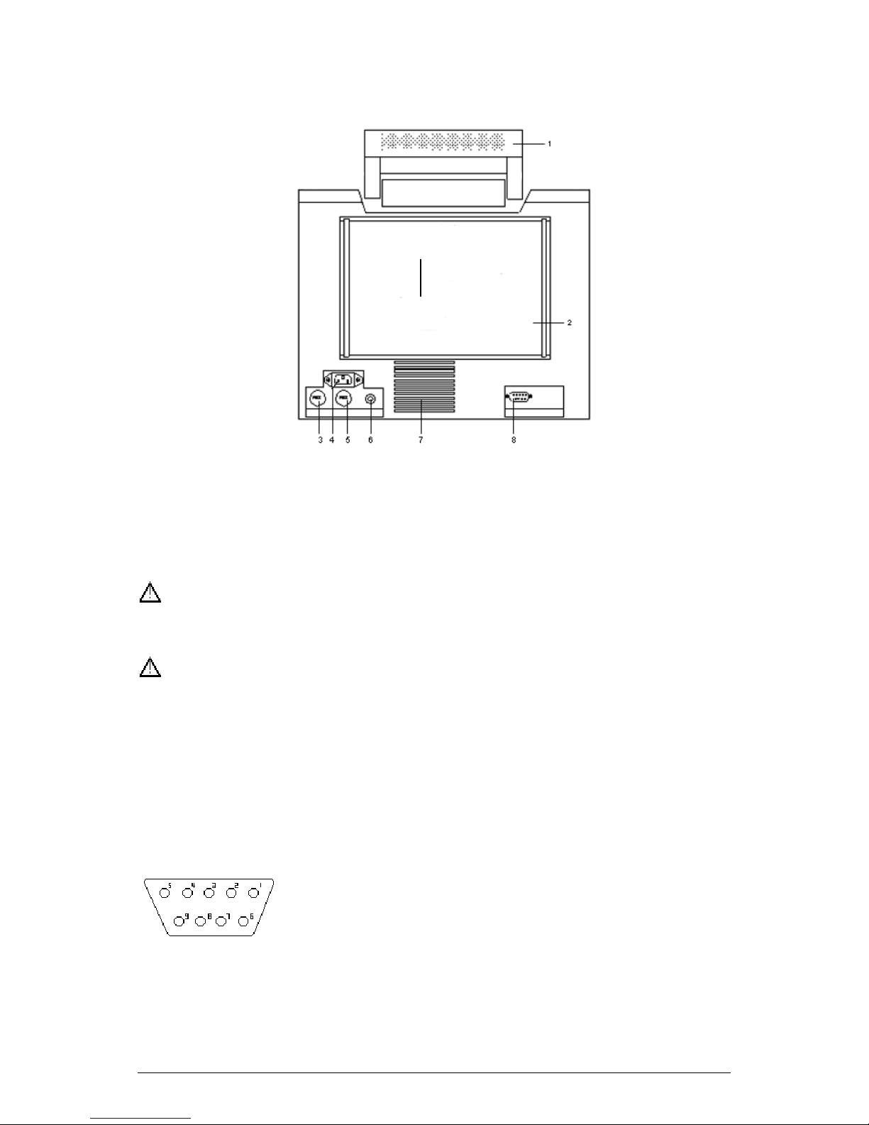
C. Rear Panel
The rear panel of Omni is as shown in Figure 3-2.
Fig. 3-2 Rear Panel Diagram
1. Handle 2. Product label 3. Fuse 1
4. 110-230VAC, 50/60Hz, external power supply socket
5. Fuse 2 6. Equipotentiality 7. Heat Exhaust
8. RS422 Communication port
RS422 communication port can only be connected with Infinium Medical’s
central station.
Accessory equipment connected to the analog and digital interfaces must be
certified according to the respective IEC standards ( e.g. IEC 950 for data
processing equipment and IEC 601-1 for medical equipment ). Furthermore, all
configurations shall comply with the valid version of the system standard
IEC 601-1-1. Everybody who connects additional equipment to the signal input
part or signal output part configures a medical system, and is therefore
responsible that the system complies with the requirement of IEC 601-1-1. If in
doubt, consult the service department or your local representative.
The definition of RS422 port is as follows,
1 N.C. No Connected
2 N.C. No Connected
3 N.C. No Connected
4 TXD+ (B) Signal Transmitted+
5 TXD- (A Signal Transmitted 6 RXD- (A) Signal Received -
7 N.C. No Connected
8 RXD+ (B) Signal Received +
B/0 2-3
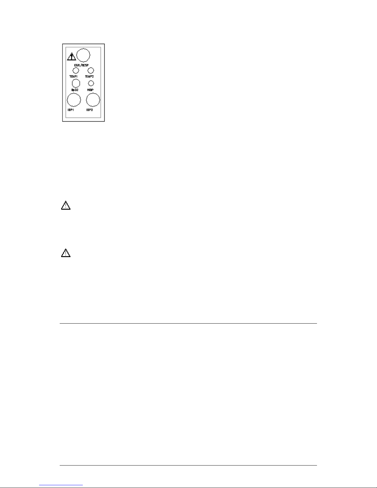
D Side Panels
There are seven sockets/receptacles on the left side panel,
respectively:
ECG This socket accepts ECG cable accompanying the patient
monitor.
SpO
NIBP This receptacle accepts the hose connector plug
TEMP1 This receptacle accepts the temperature probe.
TEMP2 This receptacle accepts the temperature probe.
IBP1/2 There are two sockets on the right side panel of the IBP measurement
module, accepting the IBP cable.
Please consult the specific items in the parameters’ chapters.
There is an optional built-in recorder on the right side panel of the patient monitor
which is used to print the monitoring waveform and data.
Loading thermal paper: Open the door of the recorder by pressing in the
direction as indicated by the arrow, place print paper inside according to the diagram
on the recorder panel. Pull the paper until a few inches of paper is showing. Close the
side cover and now the recorder is ready to print.
This socket accepts SpO2 extension cable.
2
from the blood pressure cuff.
NOTE: The recorder in Omni is optional. If you have not ordered the recorder,
please disregard the descriptions that refer to the recorder.
E. Technical specification
1. Safety Standards & Quality System
Designed to meet EN 60601-1:1990 + A1:1993 + A2:1995
Class I equipment, internally powered equipment, double insulated
Type BF and CF applied parts
ISO9001 & EN46001 Certified
2. Power Requirements
Power Supply 110-230 VAC, 50/60Hz
Input Power
Fuses Two fuse sockets in the rear panel indicated by symbol of
Battery 12V/4.0AH sealed lead-acid
B/0 2-4
d115VA
fuse, T2.0AL, 250V ~

Charge time
Operating time
t8 hours
t1.5 hours (full recharge)
Battery Charging Method Automatic charging after monitor is connected to AC power
supply (with charge protection function)
Discharge Protection When powered by battery, the monitor will be automatically
turned off when battery power is almost used up.
3. Performance Specifications
(1) ECG
Patient Safety Standard IEC60601-1-1988
CMRR
Measure Range
t60dB (Common Mode Rejection Ratio)
20 ~ 254bpm r 1bpm
Heart Rate Averaging 8 second average
ST Segment Range -0.8 ~ + 0.8mV
Interface AAMI 6-pin
Lead Selection I, II, III (3 lead mode)
I, II, III, aVR, aVL, aVF, V (5 lead mode)
Lead Fault Alarm Audible, Visual
Input 5-lead ECG patient cable
QRS Indicator Audible and Visual Alert
Waveform Storage 6 minutes
Sweep Speed 12.5/25/50 mm/sec
Gain Selection 4mV, 2mV, 1mV, 0.5mV, 0.25mV,Auto
Trends 2 hours Æ 4 hours Æ 8 hours Æ 24 hours Æ 48
hours
Patient Isolation
Frequency width
Breakdown voltage: 4000VAC 50Hz 60 seconds
Leakage current: <10PA
Monitoring mode: 0.5 ~ 40Hz (+0.4dB,-3.0dB)
Surgery mode: 0.5 ~ 20Hz (+0.4dB, -3.0dB) (not
calibration significant)
Patient Drive Current
<10PA
Enclosure Leakage Current <0.1mA
Maximum T wave Rejection Capability 1.2mV
Heart Rate Alarm Response Time < 7 seconds
Aspect Ratio 0.24 ~ 0.6 sec/mV
Defibrillator Protected & ESIS Protected Tested with 5kV
Recovery Time Following Defibrillation <5 seconds
(2) Respiration
Measurement Method Thoracic Impedance
Measure range 5 ~ 99 brpm
Accuracy r2 brpm
Refurbish time about 2 seconds
(3) Pulse Oximetry ( SpO2 )
B/0 2-5
 Loading...