


DR. BENDER GmbH
Innovative Elektrowerkzeuge
Manual for
Powerbox
PB WX2
230 V
PB WX8-10
400 V
PB WX8-10 VB
400 V
Valid from 02.2006 PB WX2 Art.-No. 101152 Subject to alterations
PB WX8-10 Art.-No. 100260
PB WX8-10 VB Art.-No. 101290
All rights reserved
DR. BENDER GmbH • D-75382 Althengstett • Tel 07051-9291-0 • Fax 07051-9291-91
Our website address is: http://www.dr-bender.de
• e-mail: info@dr-bender.de

2
Conformity Declaration
DR.BENDER GmbH
Innovative Elektrowerkzeuge
EC Conformity Declaration
for the following DR.BENDER stone processing machines
PB WX2
PB WX8/10
PB WX8/10 VB
DR.BENDER GmbH, as manufacturer, hereby declares that the electrical stone drilling machines
mentioned above comply with the requirements of the following guidelines:
- Machine guidelines (98/37/EC)
- Electromagnetic compatibility (EMC) (89/336/EEC)
- Low voltage guideline (73/23/EEC)
The following standards were applied for evaluating the machines:
a) with regard to the machine guidelines:
VDE 0740 21-22: 1994-1991
VDE 0701 Part 1: 1993
VDE 0702 Part 1: 1995
DIN EN 50144-1: 1999
DIN EN 50144-2-1: 2000
b) with regard to electromagnetic compatibility
Interfering emissions
DIN EN 55014-1: 2000 + A1: 2001 = VDE 0875 Part 14-1
DIN EN 61000-3-2: 2000
DIN EN 61000-3-3: 1995 + Cor.1: 1997 + A1: 2001
Interference immunity
DIN EN 55014-2: 1997 + A1: 2001 = VDE 0875 Part 14-2
c) with regard to the low voltage guideline
EN 61029-1: 2001
DR.BENDER GmbH
Althengstett, 29.04.2003
Industriestraße 22
D-75382 Althengstett
Tel. 07051/9291-0, Fax 07051/9291-91
B. Brehm, Management
This declaration implies no assurance of properties.
Please observe the safety regulations of the attached product documentation.

3
Contents
Page
Conformity declaration 2
Contents 3
1.0 Symbol- and Pictograph description 4
1.1 Function description 4
2.0 General instructions 5
2.1 Technical description 5
2.2 Application 5
2.3 Safety 6
3.0 Transport and storage 6
3.1 Transport 6
3.2 Storage 6
4.0 Main dimensions and technical data 7
4.1 Dimensions 7
4.1.1 PB WX2 Powerbox 7
4.1.2 PB WX8/10 and PB WX8/10 VB Powerbox 7
4.2 Technical Data 7
4.2.1 PB WX2 Powerbox 7
4.2.2 PB WX8/10 and PB WX8/10 VB Powerbox 8
4.3 Operating temperatures 8
5.0 Commissioning 8
5.1 Mains connection 8
5.2 Water connection - PB WX8/10 and PB WX8/10 VB Powerbox 9
5.3 Powerbox operation 9
5.4 Automatic overload cut-off 10
6.0 Safety instructions 10
7.0 Maintenance and care 11
7.1 Daily care 11
7.2 Quarterly 11
8.0 Warranty 11
9.0 General safety instructions 12
10.0 Spare parts lists 14
10.1 PB WX2 Powerbox 14
10.2 PB WX8/10 Powerbox 16
10.3 PB WX8/10 VB Powerbox 18

4
Warning
It is compulsory to observe the safety instructions included in this manual!
Special designs and versions may differ from the standard models in terms of their technical
details. If any points are unclear, we urgently recommend that you contact DR.BENDER GmbH,
indicating the machine type and machine number.
1.0 Symbol- and Pictograph description
This sign tells you rules, if you not pay attention for this your health and the function of
the machine is in danger. You have no warranty if the machine breaks down because
you not looking about this.
1.1 Function description
PB WX2:
PB WX8/10:
PB WX8/10 VB:
230 V mains
connection
Cooling fins
400V mains
connection
Water connection
Remote control
Emergency stop
button
Motor controller
On-button
Off-button
HF- connecting sleeve
3.5 kW
HF-connecting sleeve
8/16 kW
Handle
Feed motor 1
connecting sleeve
Feed motor 2
connecting sleeve

5
2.0 General instructions
2.1 Technical description
BELUGA, ORCA and SQUATINA represent a completely new generation of driving machines used for
stone processing. The highly extensive modular design principle provides the nowadays so important
flexibility in performing cutting operations in concrete and stone. In the process, quite newly developed high
frequency elements are employed in the motor. The frequency range is adjusted within 0 – 1000 Hz by
means of the frequency changer integrated in the Powerbox. At 1000 Hz, the rotor reaches a speed of
30,000 min
-1
. A main advantage results from a weight / performance ratio (motor output = 11 kW / weight =
21.5 kg -> 0.51), so far unequaled with the conventional technology, such as the BBM33extra type (motor
output = 2.4 kW / weight = 13.5 kg -> 0.17). This means that the weight of the machine could be reduced
three times by means of the high frequency technology. Further advantages result from the infinitely
variable speed regulation. Thus, each tool diameter may be assigned its optimum speed, in order to
achieve the best cutting speed possible at the tool. Furthermore, the speed may be continuously reduced in
the process when steel reinforcements appear, thus providing its optimum adaptation to the working
progress. In this case, it is possible to run at much higher cutting speeds (Caution! They depend on the
tool), achieving an up to 150% faster working progress. In the case of conventional machines, the torque
dramatically decreases at high speeds, rendering this advantage impossible.
2.2. Application
The driving machines and the appropriate Powerboxes can be used for the purposes outlined by the data
on the model plate. If you are using special machines, the details in the quotation and order confirmation
also apply.
The driving machines and the Powerboxes are supplied as standard in protection class I; only this can
guarantee the full high quality protection of the FI switch.
If you use suitable saw blades and core bits, you will be able to cut in the most diverse material types:
- concrete (even if it contains thick reinforcement steel)
- sandstone and limestone
- all building materials for solid walls
- asphalt carpets
The machine must be
- PB WX2:
directly connected to 230 V mains using a personal safety switch (PRCD);
- PB WX8/10 und PB WX8/10 VB:
connected to a duly grounded EEC socket (EEC 5 poles, 3P+PE 32A 6h – 400V). No zero
conductor is required;
- operated with a pre-connected all-current failure FI protection or protection insulating transformer
in order to ensure the protection of the operator.

6
2.3. Safety
Warning
Before using the machine for the first time, check the conformity of the data on
the model plate with the mains voltage and frequency. Voltage deviations of
± 5 % and/or voltage deviations of ± 2 % are permissible. Repairs may be
carried out only by adequately qualified persons, based on their training and experience.
The following points are to be given special attention:
- the technical data and information on the permitted use of the machine (commissioning, ambient
and operating conditions) which are set out, among others, in the catalogue, the operating manual,
the model plate data and the other product information;
- the relevant accident prevention regulations;
- the professional use of tool;
- the use of personal safety equipment;
- not defective and unchanged power boxes correspond to the relevant standards and keep all
demanded limit values concerning EMV (breakdown radiation and noise immunity). Permissible
electromagnetic fields are radiated nevertheless. Electromagnetic fields can disturb the enterprise
of vital electronic devices (e.g. cardiac pacemakers). Carriers of cardiac pacemakers should ask
therefore their physician.
- a professional grounding must be ensured with enterprise at a generator.
- when using within “sensitive ranges” like airports, hospitals or official radio and broadcasting
stations the technical line locally should be informed about the use of frequency-regulated
equipment.
3.0 Transport and storage
3.1 Transport
Warning
The Powerboxes are to be checked for signs of transport damage on receipt.
Possibly existing damages must be basically documented in writing.
3.2. Storage
If possible, the storage site should be dry, clean and have a constant temperature.
7
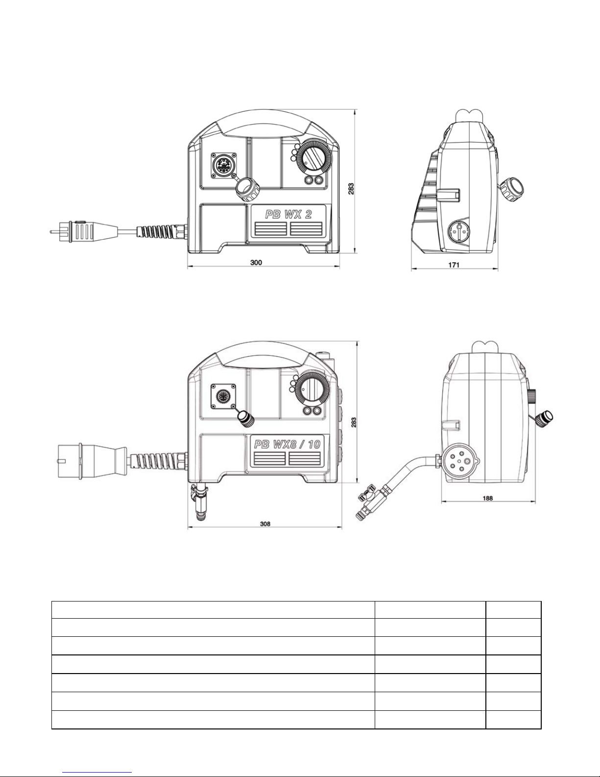
4.0 Main dimensions and technical data
4.1 Dimensions
4.1.1 Powerbox PB WX2
4.1.2 Powerbox PB WX8/10 and PB WX8/10 VB
4.2 Technical data
4.2.1 Powerbox PB WX2
Rated voltage 230
V
Current consumption 16
A
Power requirement 3,500
W
Frequency 50 – 60
Hz
Protection class IP 67
-
Cooling medium air
-
Weight 8.5
kg

8
4.2.2 Powerbox PB WX8/10 and PB WX8/10 VB
Rated voltage 400
V
Current consumption 15 / 23
A
Power requirement 8,000 / 16,000
W
Frequency 50 – 60
Hz
Protection class IP 67
-
Cooling medium water
-
Weight 12.5
kg
4.3 Operating temperatures
In case of sufficient cooling of the system, the PB WX8/10 Powerbox takes on the cooling water
temperature. The casing of the PB WX2 may take on temperatures of up to 80°C. You should not worry
about this, as it is normal. That is why you should hold the PB WX2 Powerbox by the handles.
5.0 Commissioning
5.1 Mains connection
Important
Check that the mains voltage is identical to the voltage specified on the model
plate.
Remove the protecting caps from the plug
connections. These protecting caps prevent the
penetration of water in unplugged condition, thus
increasing the service life of the high-grade cable
connections considerably.
Connect the lead of the driving
machine (e.g. Squatina 400, s
see illustration on the right) to
the round socket situated on the
front side of the Powerbox.
Tighten up the castle nut of the
screwed cable joint in order to
obtain the required IP 67
protection.
Connect the PB WX8/10 and PB WX8/10 VB type Powerbox to the mains via allcurrent failure FI protection or protection insulating transformer and coded 6 h CEE plug. Connect the PB
WX2 type Powerbox to the 230 V mains via PRCD.
Use only extension cables with protective conductor and adequate cross-section. Too low cross sections
may lead to excessive power loss and cause motor and cable overheating. An extension cable should be
secured with an overload cut-off switch. Recommended cable cross sections:
Rated current = 16 / 23 A
Cable length m 7.5 15 25 30 45 60
Cable cross section mm
2
444466

9
5.2 Water connection - PB WX8/10 and PB WX8/10 VB Powerbox
The water should flow first through the WX8/10 and
WX8/10 VB type Powerboxes, then through the driving
machine and only afterwards reach the saw blade or
core bit. Therefore, connect the water supply to the
water inlet (with ball plug valve) provided on the
Powerbox. The water outlet of the Powerbox will be
connected to the water inlet of the driving machine (for
instance Squatina 400, see illustration on the left).
Caution: if possible, do not exceed the maximum
water pressure of 3 bar.
The Powerbox and the motor are water-cooled.
Therefore, make sure to provide sufficient cold water
in operation (the cooling water should not exceed
30°C). The machine must be operated with at least
1/2 liter water per minute at full load. Use only pure
tap water, no dirty water or sewage, otherwise the heat transfer at the cooling surfaces is no longer
ensured and the motor may suffer irreparable damage.
The PB WX2 Powerbox is air-cooled and consequently requires no water connection.
5.3 Powerbox operation
Set the motor controller on the Powerbox to the desired speed. The
maximum speed will be obtained when the adjusting wheel is
completely turned to the right. By this adjustment, the range is set
from zero to the final speed. This speed range will then be at your
disposal at the accelerating switch
placed on the handle of the tool.
When pulled through, the
accelerating switch (of Squatina 400,
for instance) gently increases the
speed. The adjusting wheel enables
the additional decrease of the speed
to the final one. When turned to the
right up to the backstop, the entire
final speed that was preset on the
Powerbox will be available. The
arresting knob of the accelerating
switch has no function in this application.
When connecting the Powerbox to the mains, a brief self-test of the
electronic unit is carried out. All LED-s successively light up in the process
for a short time (for about 2 seconds).
The green LED
The green button on the Powerbox is used to turn the Powerbox on stand-by. When switched on, the green
LED by the speed adjuster lights up.
The yellow LED
The lighting up of the yellow LED indicates the operation with the maximum available power of the system;
the driving machine simultaneously sets back the speed a little, so that you will also have an additional
acoustic signal in order to decrease the feed power to some extent. You may work continuously in the
yellow field, the machine will not be damaged.

10
The red LED
When the red LED lights up, the driving machine is in the excessive temperature field. In this case, the
driving machine will stop. Wait till the driving machine cools down and start it again by means of the green
button on the Powerbox.
The red LED also lights up if there is a fault; in this case, the driving machine stops. This usually happens
in case of suddenly occurring very high overload (seizure). Therefore the driving machine will be switched
off for machine safety reasons. The red LED goes off when the machine is turned on again with the green
button and the green LED indicates that the machine is again operational (reset-function).
PB WX8/10 and PB WX8/10 VB Powerbox:
In case of sudden hazard, the system may be switched off by pressing the
emergency stop button, located near the handle. This operation may also be
performed by a third person; for this reason, always place the Powerbox at
some distance from the place of work.
After you have finished your work, switch off the system by means of the red
button.
If the red LED does not go off and the green LED does not light up either, there is a fault at the Powerbox
or at the driving motor. Contact an authorized workshop.
5.4 Automatic overload cut-off
As already described under 4.3, the machine automatically stops in case of persistent overload. The
resetting process is initiated by a new actuation of the green button.
6.0 Safety instructions
Important
Only use the tools under supervision. Disconnect the mains plug and check
that the switch has been turned off,
- when the tools remain unsupervised,
- during setup and disassembly works,
- in case of voltage drops (PB WX8/10, below 340V),(PB WX2, below 200V),
- in case of uneven mains voltage (phase dissymmetry) or interruption of a phase (phase failure),
- for adjusting or fitting an accessory.
Switch off the machine if it stops for any reason. This will prevent its sudden starting when unsupervised.
Do not use the machine if
- a part of the casing is missing or defective,
- the switch, lead or plug connector has suffered damage (conduct a visual inspection every day!),
- when operating the equipment, no cooling water may penetrate into the electrical components in
any position of employment,
- if water drips out of the tool, stop working and have the tool inspected by an authorized service
workshop,
- after a fault, switch it on again only when the saw blade or the core bit can be turned easily
- Check the working area with a line detector to prevent cutting through electric cables, water or
gas lines, etc.

11
7.0 Maintenance and care
Warning
Pull out the mains plug before beginning any maintenance or repair work. You
must have the tool checked by a specialized electrician after every repair
(statutory regulation pursuant to VBG4 since 1.1.1990).
7.1 Daily care
Make sure no water flows out of the tool. This may adversely affect the electrical safety of the equipment.
In this case, please seek assistance from an authorized service workshop.
Visually inspect the switch, supply lead or plug connector for damage.
After completing the work, clean the equipment.
Make sure that no water penetrates into the tools during the cleaning process.
Empty the cooling water after using the machine. (For this, open the ball cock and completely blow off the
cooling water with compressed air). This is very important particularly in winter months because of ice
formation.
7.2 Quarterly
Have the cable, switch and plug connectors inspected by a specialist (regulation pursuant to VBG4) and
document this inspection.
8.0 Warranty
In keeping with our terms of sale, we offer a warranty for twelve months from the date of sale. This refers to
the free repair of material and workmanship defects, which were verifiably caused before the sale.
An original purchase document must always be submitted in case of a warranty claim. It has to contain the
full address of the dealer, the date of purchase and the type designation of the product. The operating
instructions of the particular product and the safety instructions must have been followed.
Damages resulting from operational faults cannot be acknowledged as warranty cases.
The products of the manufacturer have been developed and produced for specific applications. No
warranty claim is accepted in case of non-compliance with the due employment according to the operating
instructions, in case of the employment for other purposes than originally intended or the employment of
inadequate accessories.
The periodical maintenance and cleaning of the products according to the directions of the operating
instructions is absolutely necessary. The intervention of third persons (opening the machine) renders any
warranty claim void.
Maintenance and cleaning operations cannot be claimed on the basis of warranty.
Make sure only original spare parts and original accessories are used. They are available at the authorized
specialized product dealer. If non-original parts are used, consequential damages and increased hazard
cannot be ruled out. The producer is not liable for such damages. Disassembled or partially disassembled
tools and those repaired with non-original parts are excluded from the warranty.
Certain components, such as carbon brushes, ball bearings, switches, power-supply lines, gaskets, etc.,
are exposed to usage dependent or to normal wear. These wearing parts are not object of this warranty.
Wearing parts are marked on the spare parts lists.

12
9.0 General safety instructions
1. Read and follow these instructions before you use the tool. Keep these safety instructions in a safe
place.
2. Keep your workplace tidy. Untidiness in the workplace can cause accidents.
3. Protect yourself from electric shocks. Observe the applicable regulations. Avoid physical contact with
earthed parts, such as pipes, heaters, furnaces and refrigerators.
4. Keep children away. Do not allow other people to touch the tool or cable, keep away from your work
area.
5. Keep your tools in a safe place. Unused tools should be kept in a dry, locked room out of the reach of
children.
6. Do not overload your tool. It will work better and more safely in the specified capacity range.
7. Use the correct tool. Do not use tools that are too weak or mounted tools for heavy work. Do not use
tools for purposes and work they have not been designed for.
8. Wear suitable working clothes. Do not wear excessively baggy clothing or jewelry, which may be
caught by moving parts. For working outdoors, we recommend the use of rubber gloves and sturdy
shoes. Wear a hairnet if you have long hair.
9. Use goggles. Use a breathing mask for work that generates dust.
10. Do not use the cable for any purpose other than that for which it is designed. Do not carry the tool by
the cable and do not use it to pull the plug out of the socket. Protect the cable from heat, oil and
sharp edges.
11. Every time before you use the tool, check the connection cable and plug for signs of damage. If they
are damaged, have them replaced by a specialist. Always keep the connection cable away from the
working area of the machine.
12. Secure the work piece. Use clamps or a vice to hold the work piece. Thus it will be held more securely
than in your hand and it will allow you to use both hands to control the machine.
13. Do not overstretch yourself. Avoid abnormal body positions. Ensure that you have a stable standing
position and keep your balance at all times.
14. Look after your materials with care. Keep your tools sharp and clean so that they may work well and
safely. Follow the maintenance instructions and the tool changing indications. Check the plug and
cable at regular intervals and have them replaced by a specialist if they suffer any damage. Check the
extension cable at regular intervals and replace damaged cables. Keep the handles dry and free of oil
and grease.
15. Disconnect the mains plug from the supply when the machine is not in use, before performing
maintenance operations and when changing the tool.
16. Do not leave tool spanners on the machine. Before switching it on, check that the wrenches and
setting tools have been removed.
17. Avoid unintentional starting. Do not carry a tool that is connected to the mains supply with your finger
on the switch. Ensure that the switch is turned off when you connect the tool to the mains supply.
18. Electric tools used outdoors and in wet areas: for additional safety, mobile tools used outdoors should
be connected to the mains supply using stray
all-current circuit breakers (FI or DI). This is particularly
important when working with freehand tools.
19. For outdoor work, use only extension cables, which are approved for this purpose and marked
accordingly.
20. Be vigilant at all times. Watch your work. Proceed sensibly. Do not use the tool if you are not
concentrating fully on what you are doing.
21. Important:
Safety equipment (such as overcurrent protection devices, undervoltage trips, safety couplings etc.)
are aids, yet they do not offer guaranteed safety. As a responsible manufacturer, we tailor these tools
to each other so that they offer the best possible protection. But without the care and caution of the
operator, these aids may even cause damage if they are used thoughtlessly. Have the slip couplings,
in particular, checked during the quarterly inspection to ensure that they are correctly adjusted and
function properly. This inspection should be conducted by the manufacturer or by an authorized
service outlet and documented.

13
22. Check the machine every day for signs of damage, conduct a visual inspection:
Before reusing the tool, carefully check the safety equipment or slightly damaged parts to ensure that
they offer perfect and proper function. Check that all moving parts function correctly, that they do not
jam and that none of the parts are damaged. All parts must be correctly fitted and satisfy all the
conditions to ensure the perfect operation of the tool. Damaged safety equipment and parts must be
repaired or replaced properly by a specialist service contractor. Do not use any tools, which cannot be
turned on and off using the switch. Pay particular attention to ensuring electrical safety: Cables?
Plugs? Switches? Do all the components satisfy safety regulations?
23. Repairs may only be carried out by trained personnel. Before being used for the first time and after all
repair work, the safety of electric tools must be checked by an electrician pursuant to VBG 4, § 5. This
inspection must also be conducted and documented at regular intervals – at least once per year.
24. Please note that as an operator, you are responsible for complying with any additional regulations. For
example, if electric tools are used in a wet and/or damp environment, the regulations of the ”Stone
and Earth” Professional Association must be satisfied.
25. Electrical safety and fire safety: just as DR. BENDER did in the last 20 years, the new version of VDE
0100 also recommends the additional safety protection and fire protection of each tool achieved by
using low cost FI and DI/PRCD circuit-breakers.

14
10.0 Spare parts lists
10.1 Powerbox PB WX2

15
Pos Article number Description Pcs.
1 101152 Control - Box 1
2 101150 Casing – rear part 1
3 801774 Gasket 1 **
4 401197 Sleeve 5
5 801712 Frequency changer, compl. 1
6 800076 Lock washer 10
7 900339 Allen screw 5
8 801397 Distance clip 6
9 801872 EMC-Filter 1
10 801749 EMC-Filter 1
11 802014 Fan 1 **
12 801773 Protection grid 1
13 900702 Fillister screw 4
14 801383 Screwed cable joint 1
15 100683 Handle bow 2
16 801733 Soft handle 2
17 801909 Grounding cable complete 1
18 900412 Slotted pan head screw 1
19 100681 Casing – front part 1
20 401433 LED cover 3
21 100170 Poti board, compl. 1
22 801810 Wiring harness FC 1
23 801963 Spring wire clip 1
24 800100 O-Ring 2 **
25 401038 Sleeve 1
26 800483 Shim 1
27 300771 Control knob 1
28 802056 Button, red 1
29 801796 Button, green 1
30 401037 Control lever 1
31 801516 Thrust member spr. 1
32 401574 Follower pin 1
33 802026 Insert socket, compl. 1
34 801779 O-Ring optional 1 **
35 802055 Fillister screw 1
36 802053 Closing cap 4
37 800077 Lock washer 7
38 900320 Allen screw 7
39 801752 Mains cable 1
40 401423 Scale 1
41 401424 Model plate 1
Wearing parts **

16
10.2 Powerbox PB WX8/10

17
Pos. Article number Description Pcs.
1 100260 Control - Box 1
2 100679 Casing - rear part 1
3 801774 Gasket 2 **
4 200755 Cooling element 1
5 801772 Gasket 1 **
6 801450 O-Ring 2 **
7 800076 Lock washer 44
8 901092 Allen screw 14
9 901093 Allen screw 2
10 801909 Grounding cable complete 2
11 900412 Slotted pan head screw 2
12 101149 Intermediate plate 1
13 801376 Spacer pin 9
14 401197 Sleeve 10
15 801329 Frequency changer, complete 1
16 900339 Allen screw 3
17 801810 Wiring harness FC 1
18 801963 Spring wire clip 1
19 801397 Distance clip 6
20 100172 400V board, compl. 1
21 301461 Component bracket, compl. 1
22 301460 Girder sheet metal 1
23 801510 Fan 1 **
24 802055 Fillister screw 4
25 800076 Lock washer 4
26 900251 Hexagon nut 4
27 900719 Allen screw 7
28 801910 Grounding cable complete 1
29 900251 Hexagon nut 13
30 801936 Single-aperture core 2
31 801938 Cable strap 2 **
32 801893 Cable strap 1 **
33 801699 Fillister screw 6
34 101191 EMC-Filter 1
35 100683 Handle bow 2
36 801733 Soft handle 2
37 100488 Emergency stop button 1
38 801875 Fastening nut 1
39 100681 Casing - front part 1
40 900309 Allen screw 7
40 401433 LED cover 3
42 100170 Poti board, compl. 1
43 801811 Cable harness button 1
44 800100 O-Ring 2 **
45 401038 Sleeve 1
46 800483 Shim 1
47 300771 Control knob 1
48 802056 Button, red 1
49 801796 Button, green 1
50 401037 Control lever 1
51 801516 Thrust member spr. 1
52 401574 Follower pin 1
53 802057 Insert socket, complete 1
54 801779 O-Ring 1 **
55 802062 Bushing closing cap 1
56 802055 Fillister screw 4
57 800299 Sealing ring 2 **
58 800020 Plug-in nipple 2
59 800040 O-Ring 2 **
60 801369 Cable gland 1
61 801370 Connection cable, compl. 1
62 801371 Connection cable, conf. 1
63 900744 Plug 1
64 401423 Scale 1
65 401425 Model plate 1
Wearing parts **

18
10.3 Powerbox PB WX8/10 VB

19
Pos. Article number Description Pcs.
1 101290 Control - Box 1
2 100679 Casing - rear part 1
3 801774 Gasket 2 **
4 200755 Cooling element 1
5 801772 Gasket 1 **
6 800076 Lock washer 46
7 901092 Allen screw 14
8 901093 Allen screw 2
9 801909 Grounding cable complete 2
10 900412 Slotted pan head screw 2
11 101765 Intermediate plate 1
12 802071 Fitting socket complete, remote control 1
13 802073 Fitting socket complete, infeed 1
14 801376 Spacer pin 11
15 401197 Sleeve 10
16 801329 Frequency changer, complete 1
17 900339 Allen screw 3
18 801810 Wiring harness FC 1
19 801163 Spring wire clip 1
20 802094 Frequency changer, Feed 1
21 101775 Circuit board, complete 1
22 301461 Component bracket, complete 1
23 301460 Supporting plate 1
24 801510 Fan 1
25 802055 Fillister screw 4
26 800076 Lock washer 4
27 900251 Hexagon nut 4
28 801397 Distance clip 6
29 900251 Hexagon nut 18
30 801789 Emergency stop board 1
31 801790 Contactor 1
32 802055 Fillister screw 6
33 900719 Allen screw 7
34 801910 Grounding cable complete 1
35 801936 Single-aperture core 2
36 801938 Cable strap 2
37 801893 Cable strap 1
38 801699 Fillister screw 6
39 101191 EMC-Filter 1
40 100683 Handle bow 2
41 801733 Soft handle 2
42 100488 Emergency stop button 1
43 801875 Fastening nut 1
44 100681 Casing – front part 1
45 900309 Allen screw 7
46 401433 LED cover 3
47 100170 Poti board, complete 1
48 801811 Cable harness button 1
49 800100 O-Ring 2 **
50 401038 Sleeve 1
51 800483 Shim 1
52 300771 Control knob 1
53 802056 Button, red 1
54 801796 Button, green 1
55 401037 Control lever 1
56 801516 Thrust member, spr. 1
57 401574 Follower pin 1
58 802057 Insert socket, complete 1
59 801779 O-Ring 1 **
60 802062 Bushing closing cap 1
61 800299 Sealing ring 2 **
62 800020 Plug-in nipple 2
63 800040 O-Ring 2 **
64 801369 Screwed cable joint 1
65 801370 Connection cable, complete 1
66 401423 Scale 1
67 401425 Model plate 1
68 401445 Remote control, complete 1
Wearing parts **
 Loading...