


DR. BENDER GmbH
Innovative Elektrowerkzeuge
Manual for
drilling motor EBM 25
EBM 25 F
115 V EBM 25 S
Valid from 01.2006 Art.-Nr. 200714 Subject to alterations
200715
200713
All rights reserved
DR. BENDER
GmbH • D-75382 Althengstett • Tel 07051-9291-0 • Fax 07051-9291-91
Our website address is: http://www.dr-bender.de
• eMail: info@dr-bender.de

2
Conformity Declaration
DR.BENDER GmbH
Innovative Elektrowerkzeuge
EC Conformity Declaration
for DR.BENDER stone processing machine
EBM 25
EBM 25 F
EBM 25 S
DR.BENDER GmbH, as manufacturer, hereby declares that the electrical stone processing machine mentioned above comply with the requirements of the following guidelines:
- Machine guidelines (98/37/EC)
- Electromagnetic compatibility (EMV) (89/336/EEC)
- Low voltage guideline (73/23/EEC)
The following standards were applied for evaluating the machines:
a) with regard to the machine guidelines:
VDE 0740 21-22: 1994-1991
VDE 0701 Part 1: 1993
VDE 0702 Part 1: 1995
DIN EN 50144-1: 1999
DIN EN 50144-2-1: 2000
b) with regard to electromagnetic compatibility
Interfering emissions
DIN EN 55014-1: 2000 + A1: 2001 = VDE 0875 Part 14-1
DIN EN 61000-3-2: 2000
DIN EN 61000-3-3: 1995 + Cor.1: 1997 + A1: 2001
Interference immunity
DIN EN 55014-2: 1997 + A1: 2001 = VDE 0875 Part 14-2
c) with regard to the low voltage guideline
EN 61029-1: 2001
DR.BENDER GmbH Althengstett, 29.04.2003
Industriestraße 22
D-75382 Althengstett
Tel. 07051/9291-0, Fax 07051/9291-91
B. Brehm,
Geschäftsleitung
This declaration implies no assurance of properties.
Please observe the safety regulations of the attached product documentation.

3
Contents
page
Conformity declaration 2
Contents 3
1.0 Symbol- and Pictograph description 4
1.1 Function description 4
2.0 General instructions 5
2.1 Application 5
2.2 Safety 5
3.0 Transport and storage 6
3.1 Transport 6
3.2 Storage 6
4.0 Main dimensions and technical data 7
4.1 Dimensions 7
4.2 Technical data 7
4.3 Noise emissions and vibrations [EN 50144] 8
5.0 Commissioning 8
5.1 Changing gear 9
5.2 Safety coupling 9
5.3 Core bits 9
5.4 To change a core bit 9
6.0 Safety instructions 10
7.0 Servicing and care 11
7.1 Daily care 11
7.2 After approx. 150 hours of use 11
7.3 After approx. 250 hours of use 11
7.4 Quarterly 11
8.0 Speed adjustment dependent on the cutting speed 12
9.0 Warranty 13
10.0 General safety instructions 14
11.0 Spare parts list 16
11.1 Motor complete EBM 23 16
11.2 Motor complete EBM 23 F 18
11.3 Motor complete EBM 23 S 20
11.4 Gear complete 22
11.5 Connection cables and accessories 24

4
Warning
The safety instructions set out in this operating manual must be followed at all
costs.
Special designs and versions may differ from the standard models in terms of their technical details. If any points are unclear, we urgently recommend that you contact DR.BENDER GmbH, indicating the machine type and machine number.
1.0 Symbol- and Pictograph description
This sign tells you rules, if you not pay attention for this your health and the function of
the machine is in danger. You have no warranty if the machine breaks down because
you not looking about this.
1.1 Function description
Drill-spindle
Nameplate
Switch on/off
Water connection
Circuit breaker and
PRCD switch
Gear control
Handle
Handle

5
2.0 General instructions
2.1 Application
Core drilling machines may be used in accordance with the data shown on the model plate. The details in
the quotation and order confirmation also apply for the use of special machines.
The core drilling machines generally comply with safety class I, this alone ensures the complete protection
of the RCCB or PRCD.
When using suitable core bits it is possible to drill holes in the most diverse materials:
- Concrete (even with thick reinforcement steel)
- Sandstone and limestone
- All building materials for solid walls
- Asphalt floors
Warning
For manual drilling the machine may only be used for dry drilling as set out in the relevant international regulations. Always use a 110 V isolation transformer and the suitable core drilling machine for wet drilling.
For stand-mounted drilling the machine may have the following
- a personnel safety switch (RCCB or PRCD) on the machine itself or
- a coded (1 h) plug, which is connected to the 115 V mains via a safety box (IP44) with an RCCB.
The core drilling machines comply with the regulations of the “Stone and Earth” professional association dated July 1989. They are machines of category II, which means that they must be mounted on
stands and stable (pursuant to DIN 57100 and VDE 0100), and the stand must be fitted with the following
- reversing lock
- water extraction device.
2.2 Safety
Warning
Before using the machine for the first time, check that the conformity of the data
on the model plate with the mains voltage and frequency. Voltage deviations of ±
5 % and/or voltage deviations of ± 2 % are permissible. Repairs must only be
completed by quality persons who have suitable training and qualifications.
The following points are to be given special attention:
- the technical data and details of the permitted use of the machine (commissioning, ambient and
operating conditions) which are set out in the catalogue, the operating manual, the model plate
data and other product information,
- the relevant accident prevention regulations
- the correct use of tools
- the use of personal safety equipment

6
3.0 Transport and storage
3.1 Transport
Warning
The core drills are to be checked for signs for transport damage on receipt. Any
damage must be documented in writing.
3.2 Storage
If possible, the storage site should be dry, clean and have a constant temperature. To ensure that the film
of lubricant in the bearings and sealing system is not lost, the motor shaft should be turned through several
revolutions by hand after a lengthy period of storage, for example at monthly intervals. The roller bearings
in the motors should be replaced (or regreased) if the period between delivery and commissioning is over
four years. If the machines are stored in adverse conditions, this period may differ considerably.

7
4.0 Main dimensions and technical data
4.1 Dimensions
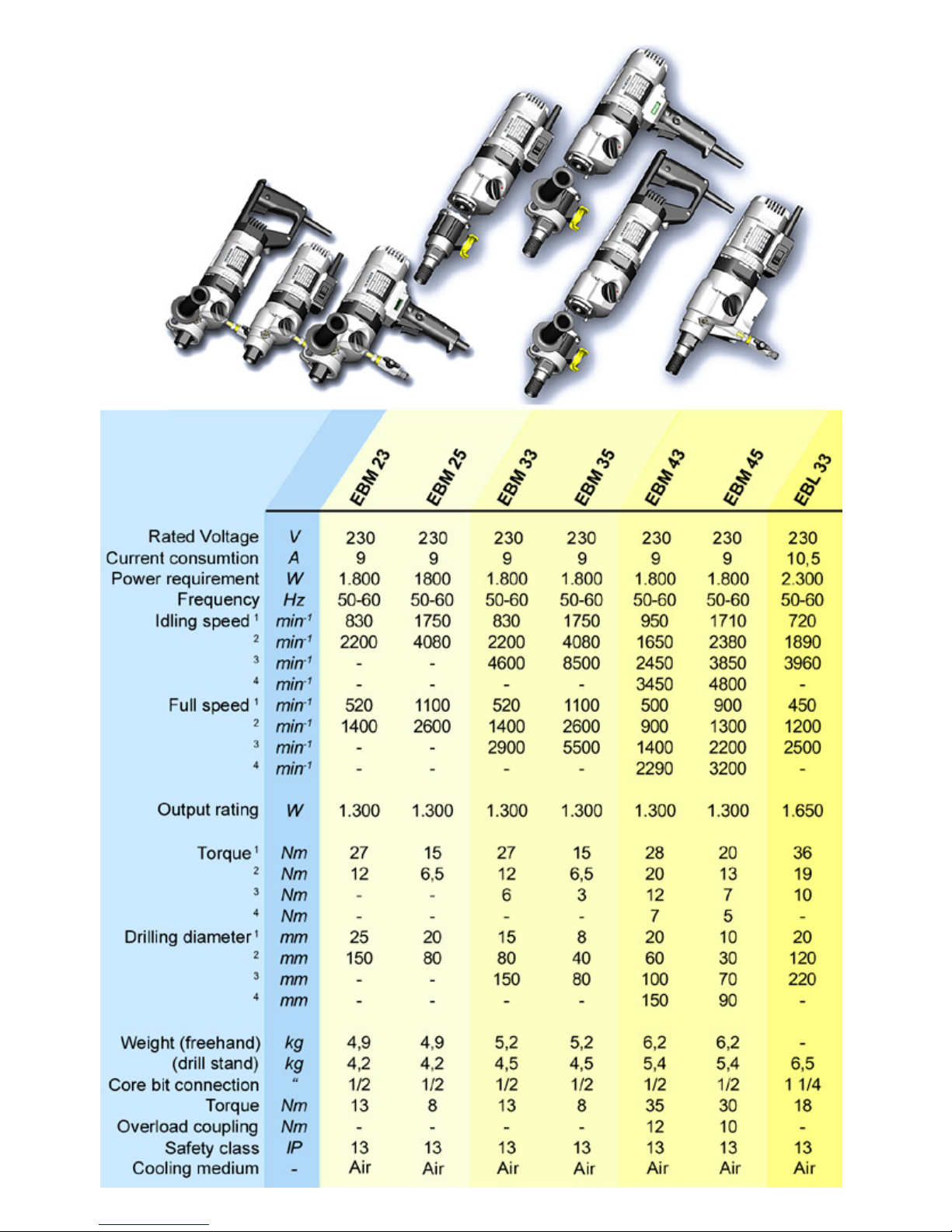
4.2 Technical Data
Rated Voltage 115
V
Current consumption 16
A
Power requirement 1800
W
Frequency 50 – 60
Hz
Idling speed 1750 / 4080
min
-1
Full speed 1100 / 2600
min
-1
Output rating 1300
W
Torque 15 / 6,5
Nm
Drilling diameter 20 – 80
mm
Weight EBM 23 4,2
kg
Weight EBM 23 S / EBM 23 F 4,9
kg
Core bit connection R ½
“
Overload coupling torque 10
Nm

8
4.3 Noise emissions and vibrations [EN 50144]
Noise level Noise level Vibration
dB(A) dB m/s
2
88 101 < 2,5
5.0 Commissioning
Check that the mains voltage is identical with the voltage specified on the model plate.
Stand-mounted:
Secure the core drilling machine and the water collection device on the drill stand with a reverse lock. The
drill stand should have high rigidity and precise, low-play guides. Ensure that the core drilling machine axis
is parallel to the drill stand axis.
Insert the core bit and set the speed. Setting instructions are given on page 12.
Connect the water supply. Important: Do not exceed the max. water pressure of 3 bar.
Connect the core drilling machine to the mains via an RCCB box and a code plug 1 h or a PRCD safety
switch.
Manually controlled:
When drilling a hole ensure that you are on a secure surface. Make particularly sure the core bit is not bent
during the drilling process and hold the core drilling machine as rigid as possible. Concentrate hard on the
work since if the core bit suddenly blocks, despite the low setting of the safety slip clutch, high forces may
be generated. If you let go of the core drilling during the drilling process, you may suffer serious injury.
Only used three-core extension cables with a protective conductor and an adequate cross-section. If the
cross-section is too low you may suffer excessive power loss and the motor and cable may overheat. An
extension cable must be secured with an overload switch. Recommended cable cross-sections:
Rated current = 16 A
Cable length m 7.5 15 25 30 45 60
Cable cross-section mm
2
2.5 2.5 2.5 2.5 2.5 4
When drilling a hole ensure that you have sufficient cooling water. Only use clean tap water, do not use
dirty or waste water. Adjust the supply to the core bit diameter and drive rating of the core drill so that you
do not exceed the rated current.

9
5.1 Changing gear
Warning
Never change gear using force and only do so when the machine is slowing
down or at a standstill.
Move the gear switch handle by approx. 40° to the next higher or lower gear. If necessary (if it is difficult to
engage the gear) turn the drive spindle briefly by hand until the gear engages easily. Never use tools (pliers, hammer, etc.) to change gear since otherwise gear damage will be inevitable.
5.2 Safety coupling
The values set out in the table are theoretical values and may be used to provide a rough guide for gear
changing. Since a whole range of other parameters also plays a major role in adjusting the speed, we cannot offer any guarantee if the tool is damaged when using the values in the table. Drilling work for which the
speeds are outside the range of the core drill (values printed in italics), should only be completed with extreme care and by trained personnel.
5.3 Core bits
All core bits with a connection thread of R ½” can be used.
Adapters can be supplied to allow core bits with other connection systems to be used.
Only use core bits that are suitable for the type of stone.
You will keep the core drill in good condition if you only use core bits that are concentric and not deformed
ones.
Ensure that the diamond segments have an adequate undercut against the core bit body.
Warning
To use wrong tools or accessories is danger for your life.
5.4 To change a core bit
The drill spindle has a right-handed thread.
Always use a 32 mm open-ended spanner to hold against the drill spindle.
Never release the core bit with (hammer) blows since this will damage the core drill.
The core bit can be removed more easily if you apply a little waterproof grease to the drill spindle thread.

10
6.0 Safety instructions
Important
Only use the core drill under supervision. Disconnect the mains plug and check
that the switch has been turned off,
- if you intend to leave the core drill unsupervised,
- for attachment and disconnection work,
- if the voltage drops (below 100 V),
- for adjustments or for fitting an accessory,
Switch off the machine if it stops for any reason. This will prevent its starting suddenly when it is not under
supervision.
Do not use the tool if
- part of the casing is missing or defective,
- the switch, lead or plug connector has suffered damage (conduct a visual inspection every day).
- Cooling water must not be allowed to ingress into the motor or the electrical components when op-
erating the core drill in any position.
- If water drips out of the overflow hole, stop work and have the core drill inspected by an authorised
service contractor.
- Only drill above your head with suitable safety equipment (water collector), RCD and transformer
protection class II.
- Connect dust extraction if required.
- After a fault do not switch on the machine again until the core bit can be turned easily.
- Check the area you wish to drill with a line detector to prevent drilling through electric cables,
- water or gas lines, etc.
Do not expose the tool to rain and use not in humidity or wet environment. Use a good lightning. Do not use
the tool near flammable fluids or gase air mixes.

11
7.0 Servicing and care
Warning
Before starting any servicing or repair work always disconnect the mains plug.
After all repairs you must have the core drilling machine inspected by an electrician (statutory regulation pursuant to VBG4 since 1.1.1990).
7.1 Daily care
Ensure that no water escapes from the overflow hole. This will cause gear damage and may reduce the
electrical safety of the core drilling machine. In this case please contact an authorised service centre.
Inspection the machine for signs of damage to the switch, mains lead or plug connector.
After completing the drilling work clean the core drilling machine. Grease the core bit mounting thread. The
ventilation slits must be kept clean and open at all times. Ensure that no water gets into the core drilling
machine whilst you are cleaning it.
To ensure that the sealing function is maintained, oil the drill spindle:
- Disconnect the core drilling machine from the water supply. Open the water connection shut-off
cock and insert a drop of oil, close the shut-off cock, place a few drops of oil into the overflow hole
and turn the machine briefly by hand.
7.2 After approx. 150 hours of use
After the first 150 hours of use, the gearbox oil must be changed.
7.3 After approx. 250 hours of use
Have the carbon brushes checked, and replaced if necessary, by an electrician.
Avoid adjusting the carbon retaining springs.
Only use original spare parts.
7.4 Quarterly
Have the cable, switch and plugs inspected by an expert (pursuant to VBG4) and document the process.
Replacing the gearbox oil will considerably extend the service life of the gear.

12
8.0 Speed adjustment dependent on the cutting speed
The values set out in the table are theoretical values and may be used to provide a rough guide for gear
changing. Since a whole range of other parameters also plays a major role in adjusting the speed, we cannot offer any guarantee if the tool is damaged when using the values in the table. Drilling work for which the
speeds are outside the range of the core drill (values printed in italics), should only be completed with extreme care and by trained personnel.
345
6
7[m/s]
1
2
4775 6366 7958 9549 11141
2.Gang
14 4093 5457 6821 8185 9549
2.Gang
1
6
3581 4775 5968 7162 8356
2.Gang
18
3183
4244 5305 6366 7427
2.Gang
20
2865
3820 4775 5730 6685
2.Gang
2
2
2604 3472
4341 5209 6077
2.Gang
24
2600 3183
3979 4775 5570
2.Gang
2
6
2204 2938 3673
4407 5142
2.Gang
28
2046 2600 3410
4093 4775
2.Gang
30
1910 2546 3183 3820
4456
2.Gang
3
2
1790 2387 2984 3581
4178
2.Gang
34
1685 2247 2809 3370 3932 2.Gang
3
6
1592 2122 2600 3183 3714 2.Gang
38
1508 2010 2513 3016 3518 2.Gang
40
1432 1910 2387 2865 3342 2.Gang
4
2
1364 1819 2274 2728 3183 2.Gang
44
1302 1736 2170 2600 3038 2.Gang
4
6
1246 1661 2076 2491 2906 2.Gang
48
1194 1592 1989 2387 2785 2.Gang
50
1100 1528 1910 2292 2600 2. Gang
55 1042
1389 1736 2083 2431 1 oder 2
60 955
1273 1592 1910 2228 1 oder 2
65 881
1100 1469 1763 2057 1 oder 2
70
819 1091
1364 1637 1910 1 oder 2
75
764 1019
1273 1528 1783 1 oder 2
80
716 955
1194 1432 1671 1.Gang
85 674 899
1100 1348 1573 1.Gang
90 637 849 1061
1273 1485 1.Gang
95 603 804 1005
1206 1407 1.Gang
100 573 764 955
1100 1337 1.Gang
110 521 694 868 1042
1215 1.Gang
120
477 637 796 955
1114 1.Gang
130
441 588 735 881
1100 1.Gang
140
409 546 682 819 955
1.Gang
Bohrø Beton Beton Gestein
[mm] armiert

13
9.0 Warranty
In keeping with our terms of sale, we offer a warranty for six months from the date of sale. This refers to the
free repair of material and workmanship defects, which were verifiably caused before the sale.
An original purchase document must always be submitted in case of a warranty claim. It has to contain the
full address of the dealer, the date of purchase and the type designation of the product. The operating instructions of the particular product and the safety instructions must have been followed.
Damages resulting from operational faults cannot be acknowledged as warranty cases.
The products of the manufacturer have been developed and produced for specific applications. No warranty claim is accepted in case of non-compliance with the due employment according to the operating instructions, in case of the employment for other purposes than originally intended or the employment of inadequate accessories.
The periodical maintenance and cleaning of the products according to the directions of the operating instructions is absolutely necessary. The intervention of third persons (opening the machine) renders any
warranty claim void.
Maintenance and cleaning operations cannot be claimed on the basis of warranty.
Make sure only original spare parts and original accessories are used. They are available at the authorized
specialized product dealer. If non-original parts are used, consequential damages and increased hazard
cannot be ruled out. The producer is not liable for such damages. Disassembled or partially disassembled
hand saws and those repaired with non-original parts are excluded from the warranty.
Certain components, such as carbon brushes, ball bearings, switches, power-supply lines, gaskets, etc.,
are exposed to usage dependent or to normal wear. These wearing parts are not object of this warranty.
Wearing parts are marked on the spare parts lists.

14
10.0 General safety instructions
1. Read and follow these instructions before you use the tool. Keep these safety instructions in a safe
place.
2. Keep your workplace tidy. Untidiness in the workplace can cause accidents.
3. Protect yourself from electric shocks. Refer to the applicable regulations. Avoid physical contact with
earthed parts, such as pipes, heaters, furnaces and refrigerators.
4. Keep children away. Do not allow other people to touch the tool or cable, keep them away from
where you are working.
5. Keep your tools in a safe place. Unused tools should be kept in a dry, locked room out of the reach of
children.
6. Do not overload your tool. It will work better and more safely in the specified capacity range.
7. Use the correct tool. Do not use tools that are too weak or mounted tools for heavy work. Do not use
tools for purposes and work for which they have not been designed.
8. Wear suitable clothing. Do not wear excessively baggy clothing or jewellery, which may be caught by
moving parts. For working outdoors, we recommend the use of rubber gloves and sturdy shoes.
Wear a hairnet if you have long hair.
9. Use goggles. Use a breathing mask for work that generates dust.
10. Do not use the cable for any purpose other that that for which it is designed. Do not carry the tool by
the cable and do not use it to pull the plug out of the socket. Protect the cable from heat, oil and
sharp edges.
11. Check the connection lead and plug every time before you use the tool for signs of damage. If they
are damaged, have them replaced by a specialist. Always keep the connection lead away from the
working area of the machine.
12. Secure the workpiece. Use clamps or a vice to hold the workpiece. This will make it more secure that
if you hold it in your hand and will allow you to use both hands to control the machine.
13. Do not overstretch yourself. Avoid abnormal body positions. Ensure that you have a stable area on
which to stand and keep your balance at all times.
14. Look after your materials with care. Keep your tools sharp and clean so that they produce good safe
results. Check the plug and cable at regular intervals and have them replaced by a specialist if they
suffer any damage. Check the extension cable at regular intervals and replace damaged cables.
Keep the handles free of oil and grease.
15. Disconnect the mains plug from the supply when the tool is not in use and when changing the tool.
15. Do not leave a tool spanner on the tool. Before switching on the tool check that the wrench and setting tools have been removed.
16. Avoid the machine starting when you do not intend it to. Do not carry a tool that is connected to the
mains supply with your finger on the switch. Ensure that the switch is turned off when you connect
the tool to the mains supply.
18. Electric tools outdoors and in wet areas: Mobile tools which are used outdoors should be connected
to the mains supply using a residual-current circuit breaker or the like for added safety. This is particularly important when working with freehand tools. If there is a water supply, you should use an
isolation transformer and a voltage supply of 115 V; please specify in your order.
19. For outdoors work, only use extension cables, which are approved for this purpose and marked accordingly.
20. Be vigilant at all times. Watch your work. Proceed sensibly. Do not use the tool if you are not concentrating fully on what you are doing.
21. Important:
Safety equipment (such as overcurrent protection devices, undervoltage trips, safety couplings etc.)
are tools but do not offer guaranteed safety. As a responsible manufacturer we tailor these tools to
each other so that they offer the best possible protection. But without the care and caution of the use,
these tools may even cause damage it they are not used properly. Have the slip couplings, in particular, checked during the quarterly inspection to ensure that it is correctly adjusted and functions
properly. This inspection should be conducted by the manufacturer or an authorised service outlet
and documented.

15
22. Check the machine every day for signs of damage, conduct a visual inspection:
Before reusing the tool, carefully check the safety equipment or slightly damaged parts to ensure that
they offer perfect and proper function. Check that all moving parts function correctly, that they do not
jam and that none of the parts are damaged. All parts must be correctly fitted and satisfy all the conditions to ensure the perfect operation of the tool. Damaged safety equipment and parts must be repaired or replaced properly by a specialist service contractor. Do not use any tools, which cannot be
switched on and off using the switch. Pay particular attention to ensuring electrical safety: Cables?
Plugs? Switches? Do all the components satisfy safety regulations?
23. Repairs may only be completed by trained personnel. Before being used for the first time and after all
repair work, the safety of electric tools must be checked by an electrician pursuant to VBG 4, § 5.
This inspection must also be conducted and documented at regular intervals – at least once per year.
24. Please note that as the operator you are responsible for complying with any additional regulations.
For example if electric tools are used in a wet and/or damp environment, the regulations of the
”Stone and Earth” Professional Association must be satisfied.
25. Electrical safety and fire safety: We now also recommend the additional safety and fire safety for all
out tools, as set out in the new version of VDE 0100 which can be achieved by using low cost residual current-operated circuit-breakers or DI/PRCD switches.

16
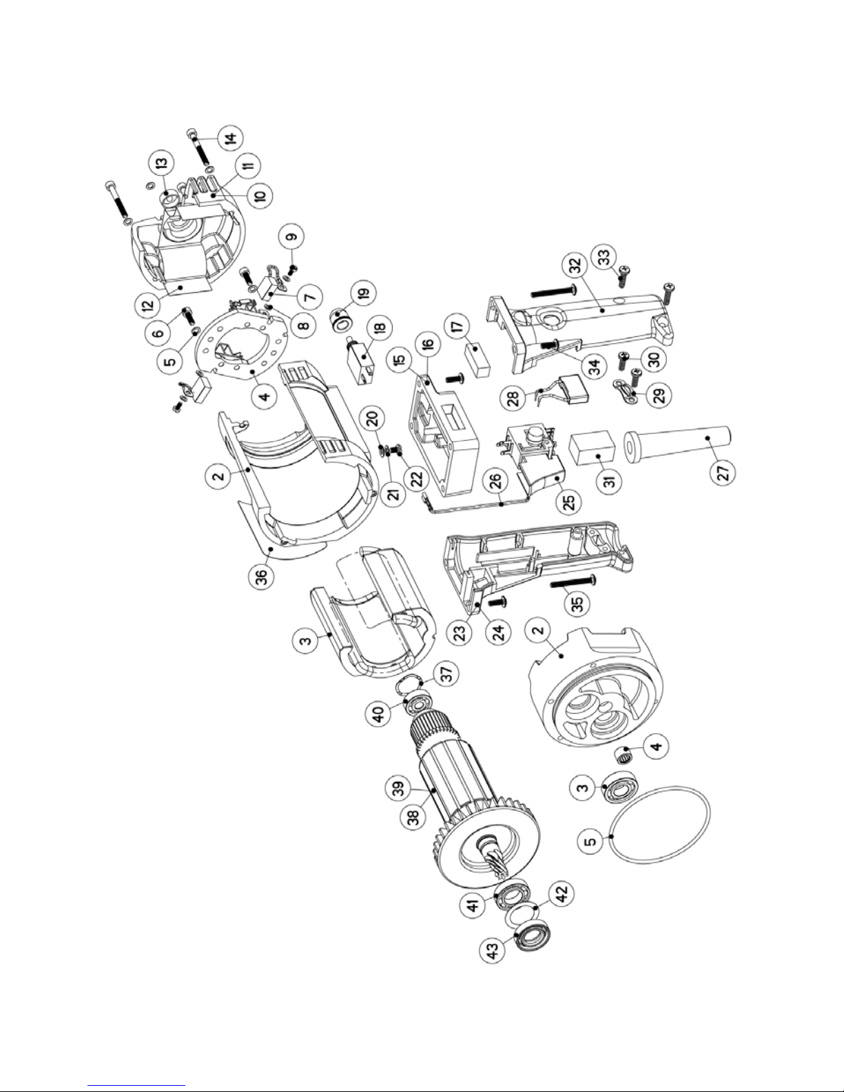
11.0 Spare parts list
11.1 Motor complete EBM 25

17
Item Art. No. Description No.
1 Motor complete 1
2 200397 Motor casing 1
3 401117 Magnet casing 1
4 401426 Brush bridge 1
5 800076 Locking washer 6
6 900339 Hexagon socket head cap screw 2
7 801425 Carbon brush 2 **
8 900183 Spring washer 2
9 900407 Cheese-head screw 2
10 401099 Bearing cap complete 1
11 200549 Bearing cap 1
12 401098 Insulation 1 **
13 800910 Spirit level 1
14 900756 Allen bolt 4
15 900231 Washer 1
16 900181 Spring washer 1
17 900412 Flat head screw 1
18 300989 Switch box complete 1
19 300891 Switch box 1
20 801422 Toggle switch 1
21 801221 Strain-relief clamp 1
22 900699 Cross recessed pan head tapping screw 2
23 801427 Cable grommet 1 **
24 801220 Interference-suppression capacitor 1
25 900337 Allen bolt 4
26 801017 Information plate 1
27 800266 Ball bearing compensating disc 1
28 401326 Armature, complete 1
29 401325 Armature 1
30 900001 Grooved ball bearings 1 **
31 900002 Grooved ball bearings 1 **
32 800035 Sleeve 1
33 900708 Shaft sealing ring 1 **
Item Art. No. Description No.
1 301057 Intermediate cover, complete 1
2 200794 Intermediate cover 1
3 900495 Grooved ball bearings 2 **
4 900170 Needle sleeve 1 **
5 800099 O ring 1 **
Wearing parts**
18
11.2 Motor complete EBM 25 F

19
Item Art. No. Description No.
1 Motor complete 1
2 200397 Motor casing 1
3 401117 Magnet casing 1
4 801426 Brush bridge 1
5 800076 Locking washer 6
6 900339 Hexagon socket head cap screw 2
7 801425 Carbon brush 2 **
8 900183 Spring washer 2
9 900407 Cheese-head screw 2
10 401099 Bearing cap complete 1
11 200549 Bearing cap 1
12 401098 Insulation 1 **
13 800910 Spirit level 1
14 900756 Allen bolt 4
15 401101 Control box complete 1
16 401100 Control box 1
17 801200 Spirit level 1
18 800727 Circuit breaker 1
19 800134 Protecting cap 1 **
20 900231 Washer 1
21 900181 Spring washer 1
22 900412 Flat head screw 1
23 301201 Handle complete 1
24 801210 Handle half 1
25 801308 Equipment switch 1
26 800731 Cable complete 1
27 801427 Cable grommet 1 **
28 801220 Interference-suppression capacitor 1
29 801221 Strain-relief clamp 1
30 900699 Cross recessed pan head tapping screw 2
31 801074 Softpack 1
32 801211 Handle half 1
33 900623 Cross recessed pan head tapping screw 2
34 801232 Button head socket screw 4
35 900702 Button head socket screw 2
36 801017 Information plate 1
37 800266 Ball bearing compensating disc 1
38 401326 Armature, complete 1
39 401325 Armature 1
40 900001 Grooved ball bearings 1 **
41 900002 Grooved ball bearings 1 **
42 800035 Sleeve 1
43 900708 Shaft sealing ring 1 **
Item Art. No. Description No.
1 301057 Intermediate cover, complete 1
2 200794 Intermediate cover 1
3 900495 Grooved ball bearings 2 **
4 900170 Needle sleeve 1 **
5 800099 O ring 1 **
Wearing parts**

20
11.3 Motor complete EBM 25 S

21
Item Art. No. Description No.
1 Motor complete 1
2 200397 Motor casing 1
3 401117 Magnet casing 1
4 801426 Brush bridge 1
5 800076 Locking washer 6
6 900339 Hexagon socket head cap screw 2
7 801425 Carbon brush 2 **
8 900183 Spring washer 2
9 900407 Cheese-head screw 2
10 200569 Cap 1
11 401098 Insulation 1 **
12 200812 Handle complete 1
13 801226 Handle right 1
14 801225 Handle left 1
15 801361 Cap 1
16 801224 Equipment switch 1
17 801427 Cable grommet 1 **
18 800727 Circuit breaker 1
19 801364 Cable complete 1
20 800134 Protecting cap 1 **
21 801221 Strain-relief clamp 1
22 900699 Cross recessed pan head tapping screw 2
23 801220 Interference-suppression capacitor 1
24 801074 Softpack 1
25 900698 Cross recessed pan head tapping screw 3
26 900704 Hexagon socket head cap screw 4
27 900231 Washer 1
28 900181 Spring washer 1
29 900412 Flat head screw 1
30 401130 Control box cap 1
31 801232 Button head socket screw 4
32 801017 Information plate 1
33 800266 Ball bearing compensating disc 1
34 401326 Armature, complete 1
35 401325 Armature 1
36 900001 Grooved ball bearings 1 **
37 900002 Grooved ball bearings 1 **
38 800035 Sleeve 1
39 900708 Shaft sealing ring 1 **
Item Art. No. Description No.
1 301057 Intermediate cover, complete 1
2 200794 Intermediate cover 1
3 900495 Grooved ball bearings 2 **
4 900170 Needle sleeve 1 **
5 800099 O ring 1 **
Wearing parts**

22
11.4 Gear complete

23
Item Art. No. Description No.
1 300911 Gear complete 1
2 200391 Gear casing 1
3 100723 Control grip 1 **
4 801367 O ring 1
5 401038 Sleeve 1
6 401036 Switch handle complete 1
7 900623 Fillister self-tapping screw 1
8 900020 Shaft sealing ring 1 **
9 900019 Shaft sealing ring 2 **
10 800001 Locking ring 1 **
11 900000 Grooved ball bearing 1 **
12 800559 Locking ring 1 **
13 300773 Drill spindle complete 1
14 900013 Compression spring 1
15 900014 Ball 2
16 800000 Locking ring 2 **
17 900764 Adjusting spring 1
18 900486 Grooved ball bearing 1 **
19 401035 Control wheel complete 1
20 300882 Control connector 1
21 900765 Adjusting spring 1
22 300774 Control wheel 1 / Loose wheel 1
23 300775 Control wheel 1 1
25 401039 Reduction shaft complete 1
26 300778 Reduction shaft 1
27 400135 Brake disc 2 **
28 401331 Reduction wheel complete 1
29 300985 Reduction wheel 1
30 401041 Bearing sleeve 1 **
31 400137 Compression washer 1
32 900018 Disc spring 2
33 900008 Hexagon nut 1
34 800027 Sealing ring 3 **
35 800026 Sealing screw 2
36 900012 Cylindrical pin 1
37 800076 Locking washer 3
38 900677 Allen bolt 3
39 800359 Water connection complete 1 **
40 800415 Hose complete 1
41 800028 Sealing ring 1
42 800023 Ball cook complete 1
43 800299 Sealing ring 1
44 800020 Slot-in nipple 1
45 800040 O ring 1
52 800417 Gearbox oil 0,2 l 1 **
Item Art. No. Description No.
47 400961 Handle complete 1
48 300822 Ring 1
49 800283 Washer 1
50 900165 Shim ring 1
51 400985 Handle 1
Wearing parts **

24
11.5 Connection cables and accessories

25
Item Article number Description No.
Plugs (no more permitted) Schuko
1 800256 Connection cable compl. 1
2 800265 Plug 1
3 800583 Connection cable, finished 1
Plugs for Germany, France, Italy PRCD
4 801244 Connection cable compl. 1
5 800265 Plug 1
6 800853 Safety switch 1
7 801236 Connection cable – S compliant 1
8 801245 Connection cable – M compliant 1
Plugs (replaced through PRCD Id-Nr. 801244) DI
9 - Connection cable compl. 1
10 800263 Plug 1
11 800583 Connection cable, finished 1
Plugs (with insulation transformer and drilling motor 115V) 12h
12 801464 Connection cable compl. 1
13 900162 Plug, 12h 1
14 800583 Connection cable, finished 1
Plugs (standard with Fi-Box IP44) 1h
15 801182 Connection cable compl. 1
16 900161 Plug, 1h 1
17 800583 Connection cable, finished 1
Plugs (Italy with Fi-Box IP44) 6h
18 801463 Connection cable compl. 1
19 900652 Plug, 6h 1
20 800583 Connection cable, finished 1
26
From our produkt
spectrum

27

28
 Loading...