

Drazice BTO 5UP, BTO 5IN, BTO 10 UP, BTO 10 IN Instructions Manual
Operation and Installation Manual
ELECTRIC WATER HEATER
BTO 5 IN/UP
BTO 10 IN/UP
Družstevní závody Dražice – strojírna s.r.o. (Works Cooperative - Dražice – Machine Plant, Ltd.)
Dražice 69
29471 Benátky nad Jizerou
Tel.: 326 370 911, Fax: 326 370 980
www.dzd.cz
dzd@dzd.cz
2
Heat losses
Heat losses
Read carefully the below instructions prior to the installation of the water heater.
INFORMATION LEAFLET pursuant to Directive No. 442//2004 Coll., and Annex No.7
Heater types
Water heaters – suspe nded, vertic al
BTO 5 IN/UP
BTO 10 IN/UP
Ener gy
efficiency
class
G 64
G 40 10 18 0,6 0,4
Wh/ 24hr/l
Nomi nal
capacity (l)
5 9 0,3 0,32
Tim e of
content
heating
(min)
BTO 5, 10 UP– non-pressure heater of 5 (10) l capacity located above the supply point
BTO 5, 10 IN– non-pressure heater of 5 (10) l capacity located underneath the supply point
Dear Customer,
The Works Cooperative of Dražice – Machine Plant, Ltd., would like to thank you for your decision to use a product
of our brand.
With this guide, we will introduce you to the use, construction, maintenance and other information.
Product’s reliability and safety is proven by tests implemented by the Engineering Test Institute in Brno.
The manufacturer reserves the right for engineering modification of the product.
The product is designed for permanent contact with drinkable water.
Guide Contents
1. PRODUCT ACCESSORIES .............................................................................................................................................................. 3
2. MESSAGE FOR CUSTOMERS ....................................................................................................................................................... 3
3. TECHNICAL DESCRIPTION .......................................................................................................................................................... 3
4. GENERAL TECHNICAL DATA ..................................................................................................................................................... 3
5. OPERATING ACTIVITY ................................................................................................................................................................. 3
6. WALL MOUNTING .......................................................................................................................................................................... 3
7. PLUMBING FIXTURE ...................................................................................................................................................................... 4
8. ELECTRIC INSTALLATION .......................................................................................................................................................... 4
9. HEATER COMMISSIONING .......................................................................................................................................................... 5
10. IMPORTANT NOTICE ................................................................................................................................................................... 5
11. FUNCTIONAL DEFECTS .............................................................................................................................................................. 6
12. FIRE-FIGHTING REGULATIONS FOR INSTALLATION AND USE OF HEATER ............................................................ 6
13. USE AND MAINTENANCE OF HEATER ................................................................................................................................... 6
14. INSTALLATION REGULATIONS ................................................................................................................................................ 7
Electricity
consum ption
for heating of
the contents
from 1 0°C to
60°C in kWh
kWh/24hr
3
IP Protection
IP 24
IP 24
1. PRODUCT ACCESSORIES
The product is packed together with service instructions and list of servicing organisations. For non-pressure
connection, no safety valve is used; the function of it is performed by a non-pressure combination faucet. The package
contains anchors and fasteners to mount the heater.
2. MESSAGE FOR CUSTOMERS
The electric heater is designed for preparation of hot water in households, cottages and various welfare facilities.
It allows installation of only one hot water consumption point. Its benefit is that it heats up water by power in an
unlimited all-day time range. The time of heating service water to the recommended temperature of 60°C is about 9 and
18 minutes, depending on the volume.
Environment Type:
It is recommended to use the product in an indoor environment with air temperatures from +2°C to 45°C and a
max. relative humidity of 80%.
3. TECHNICAL DESCRIPTION
The heater tank is plastic for non-pressure connection, the electric heating element is copper. The heater tank is
provided with a valuable polyurethane insulation, all is stored in an upper plastic container. Electric wiring is placed in
the bottom (upper) part of the heater, under the removable guard of the heater. Temperature of water can be set by a
thermostat within the range between 5°C and 75°C, using the symbols on the thermostat selector button (read more in
chapter 13). Cold water inflow is indicated with a blue ring, hot water outflow is indicated with a red ring.
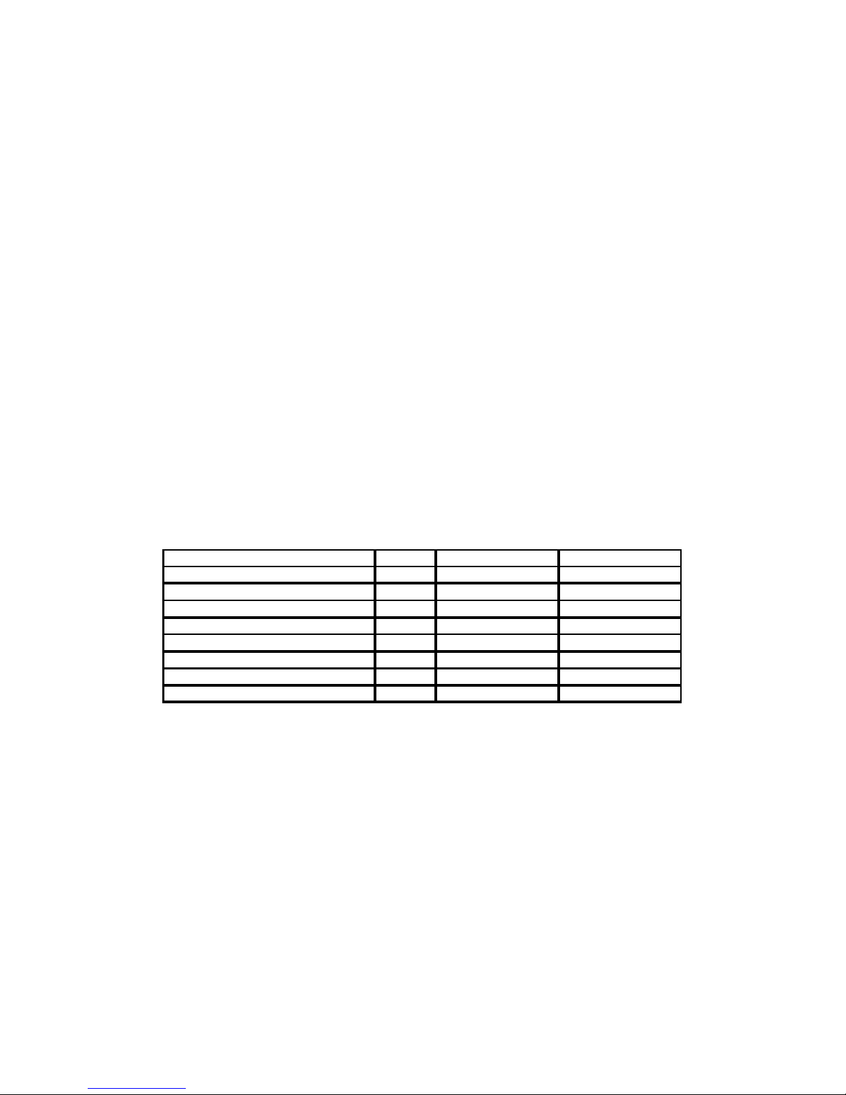
4. GENERAL TECHNICAL DATA
Type BTO 5 IN/UP BTO 10 IN/UP
Capacity l 5 10
Rated pressure MPa 0 0
Weight kg 3,5 4
Power input W 2000 2000
Time of heating from 10°C to 60°C min 9 18
Electric connection V 1 PE-N 230V/50Hz 1 PE-N 230V/50Hz
Heat losses/energy efficiency class kWh/24h 0,32 / G 0,4 / G
5. OPERATING ACTIVITY
After the heater is connected to electric network, the heating element starts heating water. The element is turned
on and off by a thermostat.
Thermostat can be set as per your need within the range from 5°C to 75°C. We recommend setting service water
to max temperature of 55°C. This temperature ensures the optimal operation of the heater. After reaching the temperature
set, the thermostat switches off the electric circuit and discontinues water heating. The control light signals if the element
is in operation (light is on) or if it is off (the light goes out). In case of longer operation without using the heated volume
the thermostat has to be set to position 9°C (set the “snowflake” symbol on the thermostat button) to avoid its freezing.
6. WALL MOUNTING
Prior to mounting check the loading capacity of the wall. If needed, reinforce it. Mount the water heater in
vertical position only. The fastening screws must have guaranteed spacing of 140 mm. Mounting dimensions are specified
on Fig. 1.
 Loading...