

Page 1
OPERATING AND
INSTALLATION MANUAL
WATER HEATER WITH HEAT PUMP
AQUA HP
Družstevní závody Dražice-strojírna s.r.o.
(Works Cooperative - Dražice - Machine Plant, Ltd.)
Dražice 69, 294 71 Benátky nad Jizerou
tel.: +420 / 326 370 911
fax: +420 / 326 370 980
e-mail: export@dzd.cz
Page 2

- 2 -
CONTENTS
INTRODUCTION ..................................................................................................................................... 5
1.1 INFORMATION PRIOR TO THE INSTALLATION ............................................................................ 5
1.2 SAFETY INFORMATION ............................................................................................................... 5
SPECIFICATIONS ..................................................................................................................................... 7
2.1 COMPONENTS ............................................................................................................................ 7
2.2 HEAT PUMP PRINCIPLE ............................................................................................................... 8
2.3 TECHNICAL PARAMETERS ........................................................................................................... 9
TRANSPORT ......................................................................................................................................... 10
INSTALLATION ..................................................................................................................................... 10
4.1 SAFETY AND CONTROL DEVICE ................................................................................................. 10
4.1.1 LOW-PRESSURE/HIGH-PRESSURE FUSE ............................................................................ 10
4.1.2 THERMAL FUSE ................................................................................................................. 10
4.1.3 TEMPERATURE SENSOR .................................................................................................... 11
4.1.4 CORROSION PROTECTION ................................................................................................ 11
4.1.5 EXPANSION TANK * .......................................................................................................... 11
4.1.6 SAFETY SYSTEM * .............................................................................................................. 11
4.1.7 PRESSURE CONTROL VALVE* ............................................................................................ 11
4.2 LOCATION ................................................................................................................................. 12
4.3 INSTALLING AIR INTAKE/EXHAUST ........................................................................................... 13
4.3.1 INSTALLATION WITHOUT AIR PIPING ............................................................................... 13
4.3.2 INSTALLATION WITH AIR PIPING ...................................................................................... 14
4.4 PLUMBING FIXTURE .................................................................................................................. 16
4.5 CONDENSATE ............................................................................................................................ 17
4.6 WIRING DIAGRAM .................................................................................................................... 18
4.7 ELECTRICAL INSTALLATION DIAGRAM ...................................................................................... 18
CONTROL AND PROGRAMMING ......................................................................................................... 19
5.1 CONTROL PANEL ....................................................................................................................... 19
5.2 FUNCTION OF THE KEYS ........................................................................................................... 19
5.3 DISPLAY ..................................................................................................................................... 20
5.3.1 DISPLAY DESCRIPTION ...................................................................................................... 20
5.3.2 SYMBOLS ........................................................................................................................... 20
5.3.3 SYMBOLS IN THE APPLIANCE'S OPERATION ..................................................................... 21
5.4 PUTTING INTO OPERATION ...................................................................................................... 21
Page 3

- 3 -
5.5 OPERATING MODES .................................................................................................................. 22
5.5.1 ECO MODE ........................................................................................................................ 22
5.5.2 AUTO MODE ..................................................................................................................... 23
5.5.3 BOOST MODE.................................................................................................................... 23
5.5.4 TCC MODE ......................................................................................................................... 23
5.5.5 LAT MODE ......................................................................................................................... 24
5.6 ADDITIONAL FUNCTIONS .......................................................................................................... 24
5.6.1 DISINFECTION MODE ........................................................................................................ 24
5.6.2 HOLIDAY MODE ................................................................................................................ 24
5.7 MENU ........................................................................................................................................ 24
5.8 CHANGING THE MODE ............................................................................................................. 25
PROPER OPERATION TEST ................................................................................................................... 25
DESCRIPTION OF PARAMETERS ........................................................................................................... 25
ERROR MESSAGES TABLE .................................................................................................................... 27
TEMPERATURE SENSOR PARAMETERS ................................................................................................ 28
TROUBLESHOOTING ............................................................................................................................ 29
MAINTENANCE OF THE APPLIANCE ..................................................................................................... 30
11.1 GENERAL MAINTENANCE ......................................................................................................... 31
11.2 DRAINING WATER FROM THE TANK ......................................................................................... 31
11.3 MAGNESIUM ANODE ................................................................................................................ 31
11.4 CLEANING OF PRESSURE CONTROL VALVE............................................................................... 32
11.5 CONDENSATE DRAIN ................................................................................................................ 32
11.6 CLEANING THE VENTILATION CIRCUIT ..................................................................................... 32
11.7 THERMAL FUSE ......................................................................................................................... 32
* not included in the delivery
Page 4
- 4 -
CAREFULLY READ THIS MANUAL BEFORE INSTALLING THE WATER HEATER!
Dear Customer,
The Works Cooperative of Dražice - Machine Plant, Ltd., would like
to thank you for your decision to use a product of our brand.
The product is not intended to be controlled by
a) people (including children) with reduced physical, sensual or mental capacities, or
b) people with insufficient knowledge and experiences unless supervised by responsible person,
or unless properly instructed by such responsible person.
Meaning of pictograms used in the Manual
Important information for heater users.
Abiding by the recommendations of the manufacturer serves to ensure trouble-free operation
and the long service life of the product.
Caution!
Important notice to be observed.
Page 5

- 5 -
INTRODUCTION
Water heater with an AQUA HP air-water heat pump certainly fulfils all your expectations, and will
comfortably serve you and achieve maximum energy savings for many years. The manufacturer devotes a lot
of time, energy and financial resources to the development of innovations that will promote energy savings
achieved by using the product. Your choice proved correct sentiment and concern about energy
consumption, therefore, a matter that affects the environment. The manufacturer has been committed
to constantly come up with innovative and effective products so that the rational use of energy could actively
contribute to environmental protection and natural resources of the planet. This manual, the purpose of
which is to inform, warn and advise in connection with the use and maintenance of this appliance, should be
retained.
1.1 INFORMATION PRIOR TO THE INSTALLATION
The electrical installation must comply with the valid national legislation applicable to electrical
installations.
AQUA HP will work only after adding the correct dose of coolant.
The maximum recommended pressure of water supplied into the hydraulic circuit is 0.3 MPa,
and the minimum pressure is 0.1 MPa.
Power is AC 230 V, 50 Hz and the power cord must be connected to a grounded receptacle.
If the power cord is damaged, it must be replaced by the manufacturer or a trained service
technician in order to prevent any risk.
AQUA HP shall only be operated if the water heater is filled with water.
Heating other than potable water is not allowed.
1.2 SAFETY INFORMATION
The appliance can be used by children from 8 years of age, persons with physical, sensory
or mental disability or people without experience or knowledge, as long as those people were
briefed on the operation of this device in a secure manner, and are familiar with the related
dangers.
The appliance cannot be played with by children.
Cleaning and maintenance must not be performed by children without proper supervision
Page 6

- 6 -
During installation:
• The installation of the water heater with heat pump must be performed by a qualified installer
who has been properly trained and qualified to this activity.
• The appliance must not be installed in locations where there is a risk of damage from impact, shock
or explosion.
• Do not unpack the appliance from the package until it is located at the installation site and is ready
for installation.
• Before connecting the appliance to the power, make sure that all hydraulic connections
are watertight.
Maintenance of the appliance:
• Maintenance of the appliance must be performed by a service technician with the exception
of regular and continuous cleaning that should be performed by the user him/herself.
• During maintenance, the appliance equipment must be disconnected from service.
• The manufacturer recommends regular annual inspection of the appliance by a qualified technician.
• Cleaning and maintenance must not be performed by children without proper supervision.
High pressure and temperature:
• The principle of operation of this appliance is associated with high temperature and high pressure.
Contacting the appliance must be done carefully so as to avoid the risk of burns and injuries
by protruding parts.
Coolant
• The coolant used in the cooling circuit is R134a, CFC free, non-flammable and without harmful effects
on the ozone layer.
• However, in accordance with the law, the liquid from the appliance must not be discharged freely
into the environment.
• The liquid in the appliance may only be handled by a qualified technician.
Information for customer
• The installer must inform users about the operation of the appliance, its dangers and responsibilities
of the user.
Page 7
- 7 -
SPECIFICATIONS
2.1 COMPONENTS
AQUA HP 250 I/IX
Page 8
- 8 -
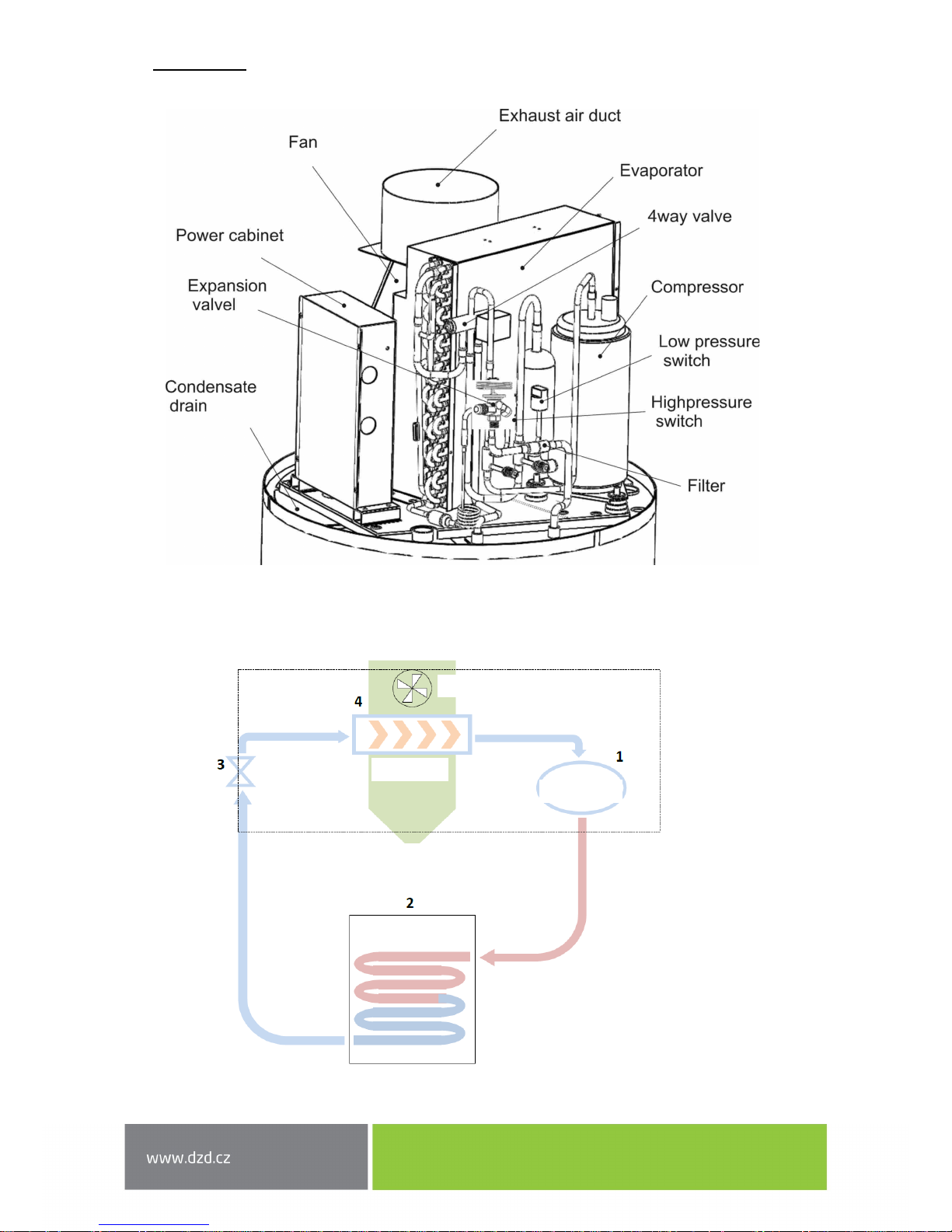
The cooling circuit located in the upper part is responsible for the transfer of heat from the ambient air
into the water.
2.2 HEAT PUMP PRINCIPLE
Fan
Compresor
Expansion
valve
Evaporator
Ambient air exhaust
(exhaust duct)
Capacitor
HOT WATER RECEPTACLE
Page 9
- 9 -
1. The coolant R134a is compressed in a highly efficient compressor that increases its pressure
and temperature.
2. In a capacitor that is not in direct contact with water, the thermal energy contained in the coolant
is transferred to the water in the hot water storage tank.
3. Condensed liquid flows from the expansion valve that is responsible for a drop in its pressure.
4. The fluid absorbs thermal energy from the air flowing through the evaporator with the help of a fan.
R134a is a HFC coolant, and therefore does not damage the ozone layer. It is characterized
by excellent chemical and thermal stability, low toxicity, is not flammable and is compatible
with most materials.
2.3 TECHNICAL PARAMETERS
Unit 250 I
Type of appliance
Water heater with heat pump
Hot water volume L 250
Weight without water
kg
83
Material of upper part
-
Stainless steel
Tank shell material - Steel sheet
Insulation - Polyurethane foam 50 mm
Mg anode
-
1”
Maximum service temperature
°C
80
Maximum service pressure
MPa (bar)
7
Test pressure
MPa (bar)
10
Heat loss
kWh/ annum
0,99
Tubular heat exchanger (diameter / length)
m
- / -
Exchanger power output 1)
kW
-
IP Protection
-
IPX1
Supply voltage - 1/N/PE ~ 230V/50Hz
Input (medium / maximum)
W
400 / 700
Output of the electrical heating element
W
1500
Heat pump output W 1800
Fan input
W
65
Maximum service current
A
3.2 + 6.8 (with backup electrical heating)
Recommended breaker
-
16A (sensitivity 30 mA)
Max temperature of hot water for heat pump
°C
55
Max temperature of hot water for heating element
°C
65
Coolant
-/kg
R 134a / 1.2
Load profile
-
XL
COP 2)
-
3.24
Heating time 2)
HH:mm
6:48
Volume of usable water 40 °C 2)
l
314
Energy efficiency class 2) - A+
Energy efficiency 2) % 138
Annual energy consumption 2)
kWh . a-1
1251
Ambient temperature limit values
°C
-5 / 40
Acoustic pressure level
dB(A)
51
Airflow
m3/h
450
Maximum length of air technical manifold
m
10
Page 10
- 10 -
a) Temperature of heating water (90/80 °C); hot water temperature (10/60 °C)
b) Temperature of heating water (70/60 °C); hot water temperature (10/60 °C)
2) A20/W10-54, according to EN16147 and applicable regulation No. 812/2013
TRANSPORT
The appliance must be transported to the installation site in the original packaging and must be
transferred in an upright position. When handling the appliance, proceed with maximum
caution to avoid the collision that could damage any part of the appliance. Make sure that the
transport belts or straps do not cause material damage. For transportation, always use suitable
means of transport (pallet truck, forklift, etc.).
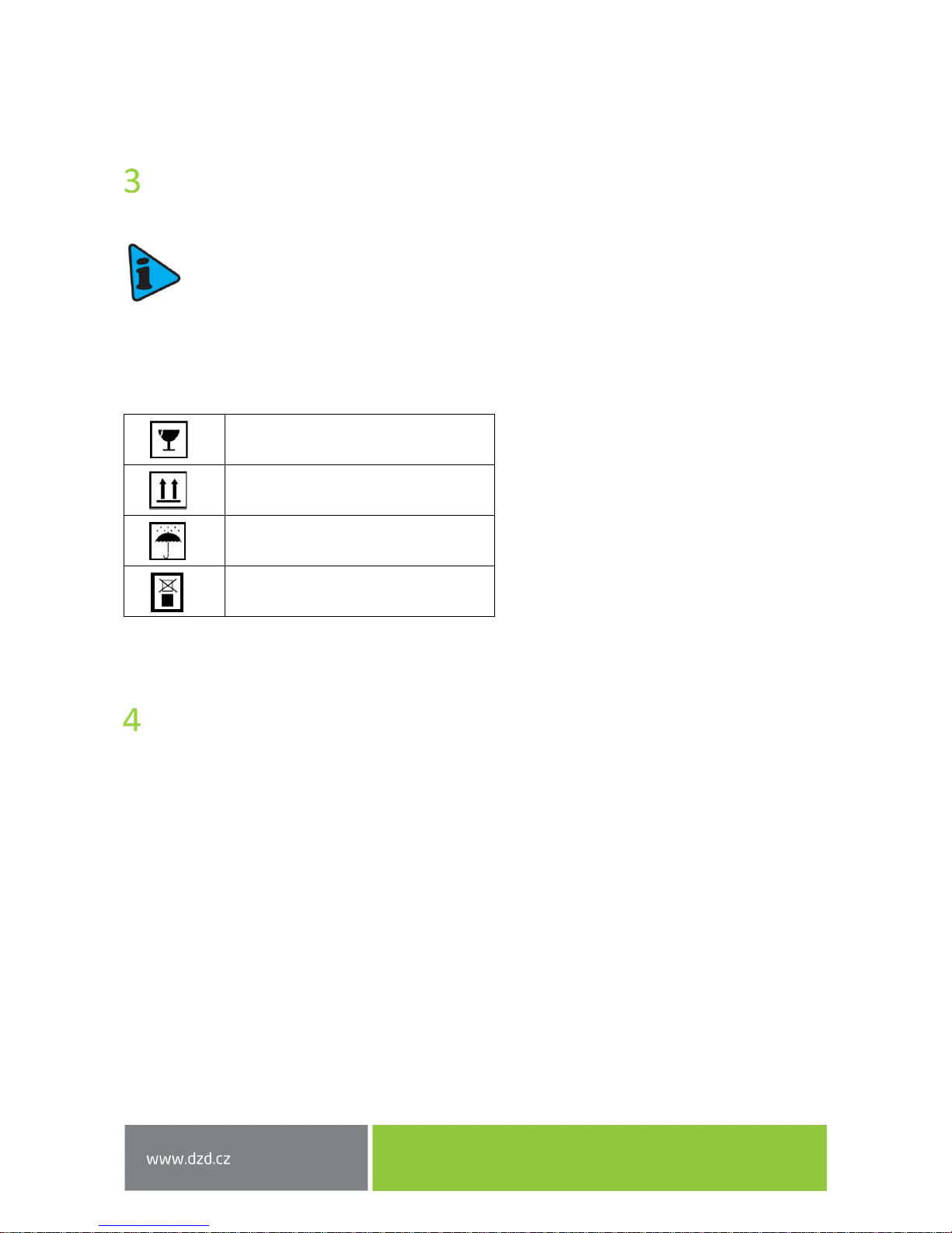
The packaging contains the following information symbols:
INSTALLATION
4.1 SAFETY AND CONTROL DEVICE
4.1.1 Low-pressure/high-pressure fuse
In preparation for operation outside the recommended operating pressures defined by the manufacturer,
the appliance switches off and the electronic panel displays an error.
4.1.2 Thermal fuse
Thermal fuse is factory set by the manufacturer, and ensures that the water temperature in the hot water
tank does not exceed the maximum value. If the temperature exceeds this value, the fuse shuts off backup
electric heating. Turning on is performed manually by a service technician after analyzing the reasons
for the switching off.
Fragile, handle with extreme caution
Make sure that the arrow always
points upwards
Keep the packaging dry
Do not stack the packaging
Page 11

- 11 -
4.1.3 Temperature sensor
Temperature sensor measures the water temperature in the hot water tank to control the entire system.
4.1.4 Corrosion protection
In addition, the top part shell of the hot water heater is corrosion resistant (it is made of stainless steel)
and the hot water tank is enamelled and also contains magnesium anode which needs to be checked
regularly, as recommended by the installer or service technician.
4.1.5 Expansion tank *
Expansion tank is a device whose purpose is to compensate for the increase and decrease in water volume
due to temperature fluctuations.
Installing the expansion tank is recommended to save water. The recommendation of installing
an expansion tank is the responsibility of the installer.
It is generally installed on a cold water pipe.
4.1.6 Safety system *
The safety system allows for protection against any non-standard situations: cooling water heater, reverse
flow of warm water back into the water main, emptying the hot water heating tank and pressurisation.
The safety valve should be calibrated to the opening pressure of 0.6 MPa. To discharge water from the hot
water tank it is necessary to close the inlet valve and open the drain valve. The drain pipe of the safety valve
should be drained into sewers by transparent hose, since water may drip or even drain off the valve.
The safety valve must be regularly opened to remove impurities and to control its patency. The drain pipe
must be installed in an area protected from frost.
4.1.7 Pressure control valve*
Pressure control valve must be installed in case of high pressure on cold water connection in order to ensure
the proper operation of the safety valve. The connection may be provided with a pressure gauge to check
the pressure.
* Parts that are not delivered by the manufacturer. Their delivery and installation must be performed
by the installer.
Page 12

- 12 -
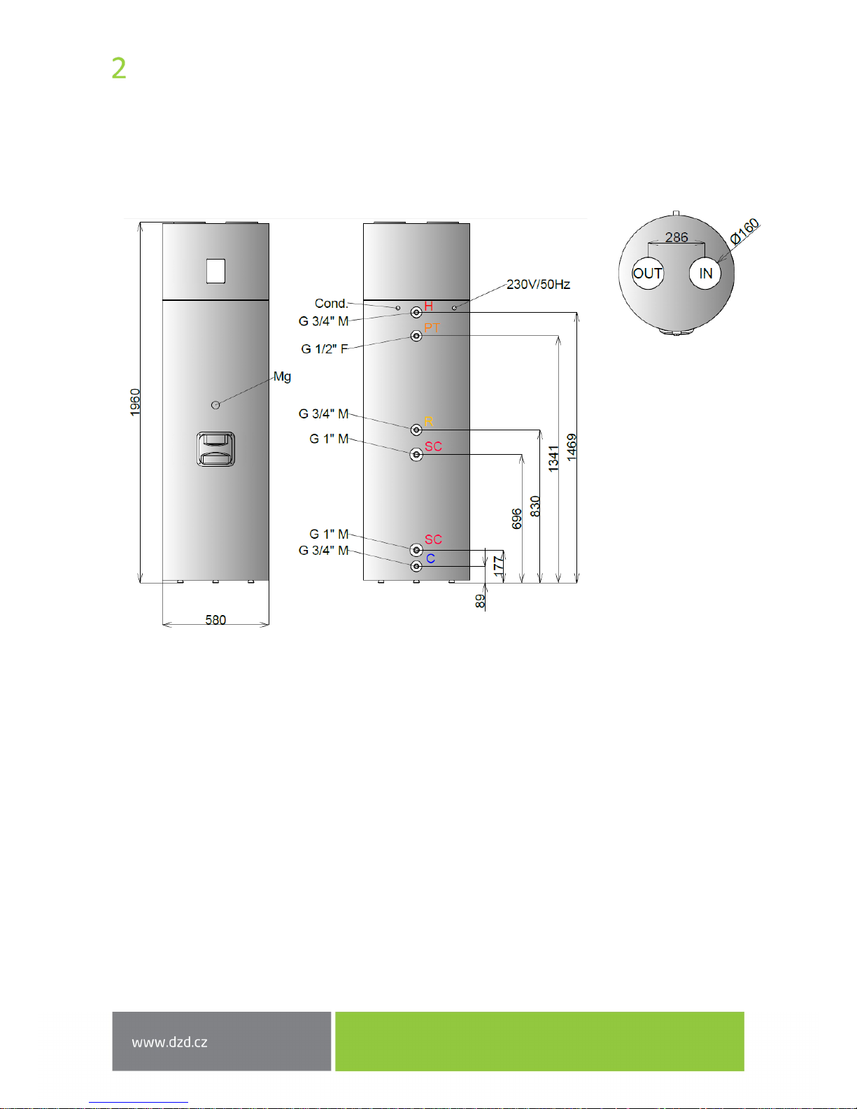
4.2 LOCATION
When placing the appliance to the installation site, keep in mind possible future service calls. To avoid having
to leave too much space behind the tank, the magnesium anode is disposed on the front side of the hot water
storage tank.
Make sure that the following minimum space is available around the appliance:
Adjust the levelling legs of the appliance. Acceptable is the tilt angle 1° rearward.
If the appliance is tilted in a different direction
than backwards, condensates are going to be
settled in the appliance.
Page 13

- 13 -
4.3 INSTALLING AIR INTAKE/EXHAUST
Since AQUA HP absorbs heat during operation, it is good to route cooled air (intake/exhaust)
to unheated spaces. The appliance will cool the room in which it is located and if it is installed
in heated rooms, cooled air should be routed to other rooms or outside.
4.3.1 Installation without air piping
The AQUA HP appliance should be installed in a location that is not too heated and can be used
for dehumidification and cooling these areas (e.g. laundry rooms, basements, etc.). The distance between
the top of the unit and the ceiling should not be less than 600 mm. If the distance between the unit
and the ceiling is less than 600 mm, it is necessary to install two elbows, as shown in the figure.
Page 14

- 14 -
4.3.2 Installation with air piping
If you use piping for airflow into spaces that do not require heating, you can:
Use the outside air
Using outdoor air, the unit can be placed either in heated or unheated room.
Use air from an adjacent room
The unit can also be placed in a heated room, but airflow should be directed to an unheated room. Keep in
mind that because of the air flow, cooling of an unheated room might affect adjacent heated rooms.
UNHEATED AREA
Min 50 m
3
HEATED OR UNHEATED
AREA
Page 15

- 15 -
Use air from an adjacent room and outside air
To supply air to the appliance, branched pipe can be used. In summer, you can use hot air from the outside
and in winter you can use the air from the unheated area.
Pipes used for air flow is not part of the appliance, and its installation is a matter of the installer;
if necessary, follow the recommendations of the manufacturer.
The pipe diameter must be 160 mm. Pipe length should not exceed 8 meters.
UNHEATED AREA
Min 50 m
3
HEATED OR UNHEATED
AREA
Page 16

- 16 -
4.4 PLUMBING FIXTURE
EXPLANATORY NOTES
[1] Shutoff valve
[2] Pressure control valve (3 bar/0.3 MPa)
[3] Return valve
[4] Safety valve (6 bar/0.6 MPa)
[5] Sink drain
[6] Expansion receptacle
[7] Drain valve
[8] Circulation pump
[9] Thermostatic mixing valve
[A] Cold water connection
[B] Hot water outlet
[C] Circulation
Page 17

- 17 -
Safety valve has to be installed on the cold water inlet into the appliance. The safety device must
comply with EN 1487: 002, maximum pressure of 6 bar (0.6 MPa). No closing armature may be
mounted between the safety valve and the tank or check valve that could disable the safety
valve.
The safety valve must be connected via a line whose diameter is smaller than the connecting
dimension. The drain must be connected to a sewage siphon or, if this is not possible, raised
to a distance of at least 20 mm from the pavement to enable visual inspection.
Pressure control valve set to 3 bar (0.3 MPa) must be installed in case of high pressure
on the cold water connection.
The manufacturer is not liable for any damages related to failure to observe these
recommendations and warnings.
Water you use may contain contaminants or substances damaging the appliance and even
harmful to your health. Make sure that you use water with a level of quality equivalent to the
consumption in your household. The following table lists some of the parameters that must
be chemically treated if exceeded.
4.5 CONDENSATE
During operation, condensation may occur. The condensate flows into a drip tray and is discharged through
a hole on the back side. The person performing the installation must connect the condensate hose supplied
by the manufacturer and direct the condensate into a drainage system or a sewer siphon.
The condensate hose must not be bent or compressed, and must be installed so as to best
ensure proper drainage of the condensate.
Hardness (ºdH) pH Treatment
3.0 to 20.0 6.5 to 8.5 No
3.0 to 20.0 <6.5 or >8.5 Yes
<3.0 or >20.0 -------------- Yes
Page 18

- 18 -
R1 - Backup electrical heating HP - High pressure switch LP - Low pressure switch
M - Compressor TB - Thermal fuse F1 - Compressor fuse (10 A)
F2 - Main fuse (10 A) S1 - Water temperature sensor S2 - Ambient sensor
S3 - Evaporator temperature sensor Fan – Ventilator V4V - 4-way valve
4.6 WIRING DIAGRAM
Water heater with heat pump can be connected to power only when the tank is filled with water.
Water heater with heat pump is supplied with a cable for connecting to a prepared grounded receptacle
(1/N/PE 230 V/50 Hz).
Wiring installation must conform to the standards applicable in the country or territory where the heater
with heat pump is installed.
The installation involves:
• Bipolar circuit breaker and Cu-cable with 3 x 2.5 mm
2
cross-section or greater
• Protective current device 30 mA
If the power cord is damaged, it must be replaced by the manufacturer or a trained service technician with
similar qualification.
4.7 ELECTRICAL INSTALLATION DIAGRAM
Page 19

- 19 -
CONTROL AND PROGRAMMING
5.1 CONTROL PANEL
The Eco control panel of the appliance is simple and intuitive. It allows you to configure several operating
parameters according to the operating mode selected by the user.
It includes six control keys (ON/OFF / CANCEL MENU, ▲ COMP, E-HEATER and OK DISINFECT and OK / LOCK)
that enable checking the operation of the appliance, monitoring the parameters and their change.
5.2 FUNCTION OF THE KEYS
Key Function Description
ON/OFF
CANCEL
ON/OFF Switch Turning the controller on and off
(CANCEL) Termination
Function of exiting to the end menu, sub-menu or cancel
function
OK /
(OK) Confirmation Confirming the parameters in the menus or submenus
(LOCK) Locked / Unlocked Locking or unlocking the keypad
MENU MENU Entering the menu
COMP Compressor ON/OFF
Pressing the key allows you to turn the compressor on and
off
E-HEATER
ON/OFF
Electrical resistance
Pressing the key allows you to enable and disable the
electrical resistance
▲
▼
Changing values
Allows you to adjust the parameter value (in menu
context)
Movement across the
menus/submenus
Function to browse menus and submenus (inside the
menu)
DISINFECT
(DISINFECTION) AntiLegionella
Press this button and the system automatically creates a
thermal shock in water to neutralize the bacteria
(Legionella)
Page 20

- 20 -
ECO
5.3 DISPLAY
5.3.1 Display description
5.3.2 Symbols
Symbol
Description
Appliance in ECO service mode
Appliance in AUTO service mode
Appliance in BOOST service mode
Timer clock control ON
Low ambient temperature protection ON
Compressor ON
Fan ON
Electrical backup ON
4-V
4-way valve ON
Keypad enabled
Keypad disabled
Disinfection function ON
Defrost function ON
Holiday mode ON
Error alert
AUTO
BOOST
TCC
LAT
45 ºC
12/10/1210:25
Er01
- S1 -
LAT
ECO BOOSTAUTO TCC
Page 21

- 21 -
OFF
5.3.3 Symbols in the appliance's operation
Symbol Description
(ON) Compressor ON
(OK) Compressor ON and setting point achieved
(TA) Electrical backup ON due to S1 < P08 and/or P07 < Temp. S3 (Auto
mode)
(TA) Electrical backup ON due to compressor ON to more than T05
(Auto mode)
(MA) Electrical backup ON manually
(ON) Electrical backup ON
(OK) Electrical backup ON and setting point achieved
(ON) Fan ON
(OFF) Fan OFF
(ON) Disinfection ON
(ON) Defrost function ON
(ON) Holiday mode ON
Error alert
5.4 PUTTING INTO OPERATION
Before activation, check the entire installation, whether everything is according to the recommendations
and make sure everything is in accordance with these instructions; only then you can connect the device
to the power outlet.
Once the appliance is connected, you need to wait a few seconds until the data are loaded, and the controller
starts.
ON
OK
TA
TC
MA
ON
OK
ON
ON
ON
ON
Page 22

- 22 -
ver
12/10/1210:25
Ver 0.M.X .X
45 ºC
12/10/1210:25
ON ON
ECO
45 ºC
12/10/1210:25
ECO
AUTO
BOOST
Then you can start the device by following these instructions:
Note 1: LED on the display indicates the status of the appliance. If it blinks, it means that the device has no
operating instructions set up. If the LED is lit and not flashing, the system works according to the given
instructions.
Note 2: Restart the unit by switching off and repeated switching on by pressing the ON/OFF button.
5.5 OPERATING MODES
AQUA HP is programmed to run in three operating modes - ECO, AUTO and BOOST that are summarized
in the following table:
User can change the operating mode at will, all they need is to simultaneously press the MENU + OK/LOCK
keys for 3 seconds. Upon entry, use the COMP ▲ and E-HEATER ▼ keys to move in the menu and submenus.
To confirm the values/parameters press the OK/LOCK key. To exit the menu, press the CANCEL key.
5.5.1 ECO Mode
In the ECO operation mode, the device operates only as a heat pump heating water in a hot water tank.
It is thus possible to achieve greater efficiency and savings for user.
Every time the user deems it necessary, they can turn on a supporting heating element in this mode manually
by pressing the (E-HEATER) key. This device automatically changes the operating mode to BOOST
and indicates this status on the display (including the heating element indication). If the heating element
is turned off manually, the appliance returns to the ECO mode.
Mode Symbol Function
ECO
Regular mode as heat pump
AUTO
Optimised management of heat pump or electrical heating
element run
BOOST
Run of both the heat pump and the electrical heating element
Controller when turned on
The system is turned off (OFF)
Press the ON/OFF switch
Press the COMP key to
start the system
ECO
ECO
Page 23

- 23 -
AUTO
5.5.2 AUTO Mode
In the AUTO mode, the unit works as a heat pump with the support of the heating element, and the operation
of the heating element is optimised in order to maintain the COP of the appliance.
The heating element starts whenever:
• is enabled by the user manually (by pressing E-HEATER).
• LP contact opens (low ambient temperature, lack of coolant, leak in the cooling circuit, etc.).
• compressor running time exceeds the T05 parameter*
• water temperature is below P08*
* The parameter is adjustable (ON/OFF)
5.5.3 Boost Mode
In the BOOST mode, the unit works as a heat pump with the support of the heating element, and the run
of the heating element isn't optimised. This mode allows users to achieve sufficiently hot water in a shorter
period of time.
5.5.4 TCC Mode
The TCC function provides the ability to achieve higher water temperatures at a time when an alternative
source of electric energy (photovoltaic system, etc.) is available.
You just need to connect the control connector
between the photovoltaic inverter and the appliance's
control panel. This connection to the panel must be
made potential-free (no voltage). The voltage on this
contact causes irreversible damage to the appliance.
If the contact is K1, it activates the TCC function, and
all sources of heat (both the heat pump and the
heating element) work according to the new
programmed operating parameters.
Note: When the contact K1 is opened, the device
operates according to the preset operating mode (Eco,
Auto or Boost) and the corresponding parameters.
Contact K1 can be thus used for the tariff control, i.e.
to switch according to the "night current". For this
purpose, connect potential-free either the timer or
the contact controlled according to the HDO signal.
BOOST
TCC
Page 24

- 24 -
5.5.5 LAT Mode
LAT mode starts automatically at a low temperature of the input air in order to protect the compressor. When
this mode is activated, the compressor shuts down and only electric heating activates. When the intake air
temperature rises, the device returns to the previously selected mode.
5.6 ADDITIONAL FUNCTIONS
5.6.1 Disinfection Mode
The AQUA HP controller includes a Disinfection (Anti-Legionella) function consisting of a water heating cycle
up to 65 °C for a time sufficient to prevent formation of bacteria inside the tank.
The disinfection function can be set automatically or manually. In the automatic mode, user can set
the function to every week or every month. Unless the automatic mode is activated, user must be activated
manually by pressing Disinfect.
At the end of this function, the system returns to the operating mode set before the activation
of this function.
5.6.2 Holiday Mode
To activate the Holiday function, it is necessary to enter the menu and set the number of days of the holiday
and the appliance automatically enters the standby mode and stays there until the last day of the holiday.
The last day of the holiday the appliance activates the disinfection function to eliminate any formation of
bacteria that could emerge in the hot water tank during the periods of user's absence.
Once the holiday is over and the disinfection programme terminates, the appliance returns to the selected
mode (ECO, AUTO or BOOST).
Note: If you set the appliance to enter into the holiday mode, but switch it OFF and ON using the ON/OFF
switch, the function will not be active. After returning from a holiday, user must not forget to turn on the
appliance and cancel the entered holiday days (value = 0). If user fails to do so, the appliance returns to the
default mode until the expiration of the specified number of the holiday days.
5.7 MENU
Every time the parameters need to be modified or new ones set during the operation of the device, user
must enter the menu.
To access the menu, it is necessary to press the MENU button for 3 seconds. Upon the entry, use the COMP
▲ and E-HEATER ▼ keys to navigate the menu and submenus. To confirm the values/parameters press
the OK/LOCK key. To exit the menu, press the CANCEL key.
LAT
Page 25

- 25 -
5.8 CHANGING THE MODE
ECO is set as the default mode for the operation of the device. If at any time the user wants to edit
the operation mode they can proceed as follows:
Unlock the keypad and hold the MENU key down for 3 seconds. Use the COMP ▲ and E-HEATER ▼ keys to
browse the menu and select F03 to enter the submenu and select the operation mode.
Note: To change the operating mode, you do not need to restart the appliance.
PROPER OPERATION TEST
To check whether your device works properly, run it and wait about 20 - 30 minutes and then check
the following:
• The air temperature at the evaporator outlet should be lower by 3-4 °C compared to the air
temperature at the inlet.
DESCRIPTION OF PARAMETERS
Code Type Description Min Max Setting
F01 Language
Portuguese
English
French
German
Italian
Spanish
Czech
English
F02 Clock Date and time
F03 Mode
Eco mode
Boost
Auto
Eco
F04 Holiday Holiday mode 1 99 0
F05 Disinfection
Disinfection function inactive
Disinfection function active once a week
Disinfection function active once a month
--- --- Monthly
F06
Parameters
P01 - required temperature, compressor 5 55 53°C
H01 - P01 parameter hysteresis 2 10 4°C
P02 - required temperature, final el. heating 1 60 53°C
H02 - P02 parameter hysteresis 2 10 4°C
P01TCC - required temperature, compressor 5 55 55°C
Page 26

- 26 -
F06
Parameters
(continued)
H01TCC - P01TCC parameter hysteresis 2 10 4°C
P02TCC - required temperature, final el. heating 1 65 60°C
H02PV - P02 parameter hysteresis 2 20 10°C
P03 - defrost start -15 10 -8°C
P04 - defrost finish 0 25 16°C
P05 - safe temperature 70 80 70°C
P06 - Anti-Legionella disinfection temperature 60 69 65°C
P07 - min evaporator temperature for final el.
heating activation
-15 20 -5°C
P07 - setting ON OFF ON
P08 - min water temperature for final el. heating
activation
1 40 30°C
P08 - setting ON OFF ON
P09 - air temperature for defrost 0 15 10°C
P10 - minimum air temperature -10 10 -5°C
H10 - P10 parameter hysteresis 2 10 5°C
T01 - delay before compressor startup 1 20 2 min
T02 - min running time before defrost 1 10 1 min
T03- max defrost time 2 15 8 min
T04 - compressor startup delay after defrost 1 10 1 min
T05- max compressor runtime 6 15 10 h
T06- defrost start time delay 30 360 60 s
T07 - startup delay after low pressure error 2 20 10 min
T08 - time interval between defrost cycles 10 120 40 min
T09 - prodleva před vyhlášením LAT 2 20 5 min
T10- min defrost time 2 10 4 min
F07 INFO List of control parameters
F08 Level
Installation technician 0022
Manufacturer ****
F09 Output test
CO - contact N.O., compressor
RE - contact N.O., final el. heating
VE - contact N.O., fan
V4V - contact N.O., 4-way valve
F10 Errors
Elist - list of error messages
Ereset - deletion of error messages
F11 Reset Restoring default settings
F12 System Compressor runtime hours
Page 27

- 27 -
ERROR MESSAGES TABLE
Symbol Description Trouble / Check
Er01 – S1
Error - temperature
sensor 1
• Damaged temperature sensor - Measure the internal resistance
of the sensor which is about 10 KΩ at the temperature of 25 °C.
• The sensor is disconnected from the controller - Make sure the
connector is properly connected to the electronic board and that
the connecting terminals are properly secured.
Er02 – S2
Error - temperature
sensor 2
Er03 – S3
Error - temperature
sensor 3
Er04 – TA
Water temperature
error
• The water temperature in the water tank is too high - check for
possible damage on the electronic board, such as a damaged
relay.
• The temperature sensor is short-circuited - Measure the internal
resistance of the sensor which is about 10 KΩ at the temperature
of 25 °C.
Er05 – S1 Probe 1 short circuit
• Measure the internal resistance of the sensor which is about 10
KΩ at the temperature of 25 °C, check for the correct connection
of the connector to the electronic board and the connecting
terminals for good condition.
Er06 – S2 Probe 2 short circuit
Er07 – S3 Probe 3 short circuit
Er08 – DF
Too many defrost
cycles in short period of
time
• Measure the internal resistance of the sensor which is about 10
KΩ at the temperature of 25 °C, check for the correct connection
of the connector to the electronic board and the connecting
terminals for good condition.
• Low ambient temperatures
• Lack of R134a
• Leakage in the circuit of the fluid
LINK
ERROR
Connection failure
between the display
and the supply board
• The connection cable between the display and the control panel Make sure the cable is in good condition and that the cables are
properly engaged (on the display and the control panel).
Page 28

- 28 -
Temperature (°C)
TEMPERATURE SENSOR PARAMETERS
Dependence of sensor's resistance on temperature
Resistance of sensor (kΩ)
Page 29

- 29 -
TROUBLESHOOTING
Trouble Potential cause What to do
Failure in the electronic
board
Power failure
Check the power supply.
Check corresponding circuit breaker.
Damaged or disconnected cable
Check the integrity (intactness) of the
electronic circuit board.
Low water temperature
or lack of hot water
Low temperature programmed
as a set point
Adjust the temperature set point.
53 °C as default factory setting.
Error activation
Check the presence of an error on the
electronic board and see the error
table.
Damaged or disconnected cable
Check the device connection to the
plug. Check corresponding circuit
breaker.
Check the integrity of cables.
Make sure the electrical cord is
connected to the power board.
Holiday mode ON Switch off the Holiday mode.
Appliance or compressor OFF See "5.4 System startup".
Use a large amount of hot water
For rapid heating of water, change the
device mode to "BOOST".
Hot water return into the cold
water circuit (safety device
installed incorrectly or
damaged)
Close the cold water inlet. Open the
hot water tap. Wait 10 minutes, and if
the water continues to flow, check the
function of the entire safety system.
Clean the safety device filter.
ECO mode selected and
ambient temperature very low
Change the device to the AUTO mode
to initialize the automatic control of
the system.
For rapid heating of water, change the
device mode to "BOOST".
Electrical heating OFF
Make sure that the backup electrical
heating is on.
Water is too hot or steam
generates
Problem with temperature
sensor
Check the errors displayed on the
screen.
Problem with thermal fuse
Check the correct function of the
thermal fuse.
Excessive use of electrical
heating as a backup (auto
mode)
Low ambient temperature
The operation of the device depends
on the conditions and the weather.
Low water temperature
The operation of the device depends
on the temperature of the inlet water.
Low voltage installation
Make sure that the installation is
powered by the voltage of the value
stated on the plate.
Page 30

- 30 -
Heat pump failure
Check the errors displayed on the
screen.
Evaporator blocked Clean the evaporator.
Fan blocked Check the fan status (dust, cable, ...).
Low hot water flow Hydraulic circuit blocked
Check the condition of the hydraulic
circuit.
Leaking safety valve
Absence or incorrect size of the
expansion tank (unless the leak
is continuous)
Installation or correct pressure in the
expansion receptacle.
High water pressure (unless the
leak is continuous)
Check the pressure control valve (if
installed).
Install a pressure control valve (if not
installed).
Power consumption is
abnormally high and
constant
Leak or blockage of the coolant
circuit.
Make sure the duct is not damaged.
Use a suitable device to check for
leaks in the circuit.
Adverse conditions of the
environment
Final electrical heating does
not work
Safety thermostat ON Check the status of the thermal fuse.
Faulty electrical heating Check the electrical heating.
Unpleasant odour
Absence of siphon or no water
in the siphon
Install and make sure there is water in
the siphon.
Condensate does not drain
Drain circuit clogged Clean the condenser circuit.
Drain pipe blocked Check the drain pipe.
Too fast magnesium anode
consumption
Magnesium anode wears in time. This wear is normal and prevents
corrosion in the tank. Wear rate varies depending on the water quality.
It is advisable to check the condition of the anode at least once every 2
years.
MAINTENANCE OF THE APPLIANCE
Prior to carrying out any maintenance work on the appliance, make sure that the appliance
is not powered.
Wait until the fan stops completely.
The liquid in the appliance may ONLY be handled by a qualified technician.
Although the coolant in the cooling circuit is ecological, it must not be discharged freely into the
environment.
Ecological disposal must be ensured.
Page 31

- 31 -
11.1 GENERAL MAINTENANCE
The coolant in the device can be handled ONLY by a qualified refrigeration technician with valid
authorisation.
Over the lifetime of the appliance, user must perform general maintenance and control of the appliance
depending on the place of installation:
• Surface cleaning of the appliance and the surrounding area with a wet cloth
• Visual inspection of the entire appliance in order to detect possible leakage and mechanical
damage to the appliance.
11.2 DRAINING WATER FROM THE TANK
Remember that the water in the hot water tank may have a high temperature, and therefore
a risk of scalding may be present.
Before emptying the hot water tank, allow temperature of hot water to drop to a level at which
scalding can no longer occur.
Once the water temperature is at a safe level at which scalding can no longer occur, proceed as follows:
• Disconnect the system from power.
• Close the inlet cold water valve and open the hot water tap.
• Open the drain valve of the system.
11.3 MAGNESIUM ANODE
The appliance is equipped with a magnesium anode that, together with the materials used in the receptacle,
ensures effective protection against corrosion.
The inner enamel surface of the tank ensures effective protection against corrosion which helps to maintain
water quality within the health parameters. However, the characteristics of water vary according
to the installation location (see Section 4.4 and warranty).
A the user's installation location the quality of water can be aggressive for the appliance. Therefore
a magnesium anode is supplied together with the device that wears over time and protects your appliance.
Wear of the anode depends on the characteristics of the water used. Checking the status of the anode
is so very important, especially in the early years of the installation:
To check the status of the anode, follow these steps:
• Disconnect the appliance from the electrical outlet.
• Shut off the water supply.
• Reduce the pressure (for example, open a hot water tap) and reduce the water level.
• Unscrew the anode using a suitable tool.
• Check the wear of the anode and replace it if necessary.
• If the diameter of the anode is less than 15 mm, it needs to be replaced.
Page 32

- 32 -
11.4 CLEANING OF PRESSURE CONTROL VALVE
For regular cleaning of the pressure control valve, proceed as follows:
• Shut off the water supply.
• Turn anti-clockwise until the spring is under tension.
• Remove the handle.
• Remove the filter and clean it.
11.5 CONDENSATE DRAIN
Remember within the routine maintenance and cleaning of the system to check the condensate drain system
and the drip tray. Clean the drip tray used because it may contain accumulated dust from outer space, which
can block the flow of condensate through the drainage holes. Make sure that the vents and the outlet pipes
of the condensate are clear.
11.6 CLEANING THE VENTILATION CIRCUIT
Make sure the suction filters are not clogged. Check them at least once a year.
Dust may settle on the evaporator. Also, clean it; eye on the evaporator fins.
Evaporator fins are very thin; there is a risk of injury.
Be careful not to damage the fins.
11.7 THERMAL FUSE
The thermal fuse is deactivated when any abnormal condition occurs in the system, so every time you want
to activate it, you must identify the problem that led to its shutdown.
If you are unable to determine what happened and the thermal fuse is still disabled, contact a service
technician to resolve the problem.
4-2-2019
 Loading...