

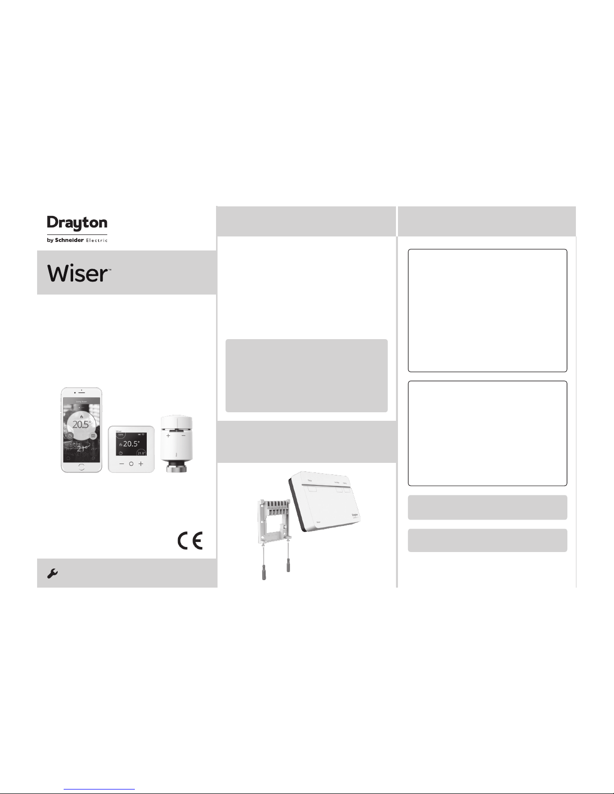
Drayton Wiser Thermostat Kit 1, Wiser Thermostat Kit 2, Wiser Multi-zone Kit 2, Wiser Thermostat Kit 3, Wiser Multi-zone Kit 1 Installation Manual
Page 1
Step 2a: Wiring - wallplate
Introduction
! DO NOT use a surface mounting box as the
wallplate is no t desig ned for this pur pose.
Step 1 Continued...
Option 1: Fitting a new wallplate
The ideal locat ion should have reasonable
lighting, good access, no condensation, no
extremes of temperature and a suppor ting surface
that fully cover s the back of the unit. Position with
70mm clear ance to the right, 25mm above and
sufficient room to access the securing screws
underneath. Fix, with terminals at the top, either
direc t to a flat wall using wall plugs and No. 6 x
1” (25mm) woodscrews, or on a flush mount ing
single conduit box type UA1 (BS4662) using M3.5
x 14 bolts. Now fit the Wiser Heat Hub
R
onto the
wallplate and tighten the securing screws. Check
the 3A fuse, and switch on the mains.
Option 2: Using an existing industry standa rd
wallplate
Loosen the securing sc rews on the old controller/
programmer and unplug it. Check that there is
70mm clear ance to the right of the wallplate and
25mm above it. Check the wiring diagr am for
your product model to compare ter minals and,
if necessar y, change the wiring of the wallplate
to suit. Now fit the Wiser Hea t Hub
R
onto the
wallplate and tighten the securing screws.
Check the 3A fuse, and switch on the mains.
One Channel:
WT714R and WV714R
Mains
fused 3A
Link for
230V output
COM
Mains
fused 3A
Mains
fused 3A
One channel only: Note that the output contac ts
are voltage-free, so power nee ds to be put on to
Terminal 1 either by link ing from Terminal L or from
a separate supply with a 3A fuse.
Note: If there is an exis ting wired thermostat
connec ted via the wallplate, this must be
disconnected, i.e. remove the thermostat wires
from the wallplate.
Note: Ensure the Heat HubR is installed in a
position wit h WiFi coverage.
Make sure mains input has a 3 amp fuse.
CAUTION! Before ins tallation, make sure the main s supply is switched off!
!
Save this guide for future reference.
If you are replacing an existing con troller/
programmer and don’t need to make any wiring
change s that ’s great news. All you need to do is
remove the old product and fit your new Wiser Heat
Hub
R
to the exis ting wallplate.
If you are fit ting a new system or require re-wiring
please contact an installer.
Welcome!
Phone: 0333 6000 622
Website: wiser.draytoncontrols.co.uk
E-mail: customer.care@draytoncontrols.co.uk
@DraytonHome
/DraytonHome
Inst aller Guide 06490238001 IssD
INSTALLATION Guide
Wiser Thermostat Kit 1
Wiser Thermostat Kit 2
Wiser Thermostat Kit 3
Wiser Multi-zone Kit 1
Wiser Multi-zone Kit 2
! IMPORTANT:
Do not at tempt to install this product if you are
not familiar with how to in sta ll mains-powered
electrical appliances.
Always switch off the main s before removing
a controller an d never fit it to a live wallplate.
Step 1:
Mounting the wallplate
Page 2
Step 2a: Wiring - wallplate
Existing OpenTherm installation
1. Remove the OpenTher m cabl es from th e exist ing
controller or thermostat.
2. Remove the OpenTherm module from the rear of
the Wise r Heat Hub
R
.
3. Wire in the OpenTherm cables into t he OpenTher m
module. I t does not ma tter which way the cables
are wired.
4. Replace the OpenTherm module into the Heat Hub
R
.
5. Wire L & N on the wallp late fro m a separa te supply
with a 3A fus e.
6. Mount th e Hub
R
on the wallplate.
Re-wi ring to Op enTherm from st andar d installa tion
Any motor ised valves need to be discon nected and
set to open. Then follow steps 2-5 above to wire in
the OpenTherm.
If your boiler supports
OpenTherm, please follow the
instructions under this step.
One Channel:
WT714R and WV714R
Two Channel:
WT724R and WV724R
Three Channel:
WT734R
Mains
fused 3A
Link for
230V output
COM
Mains
fused 3A
Mains
fused 3A
One channel only: Note that the out put contacts
are voltage-f ree, so power needs to be put on to
Terminal 1 either by linking from Terminal L or from
a separa te suppl y with a 3A fuse.
Note: If there is an exis ting wired thermost at
connec ted via the wallplate, this must be
disconnected, i.e. remove the thermos tat wires
from the wallplat e.
Note: After wiring, fit the Wiser Heat HubR onto
the wallplate and tighten th e secur ing scre ws.
Check th e 3A fuse and s witch on the mains .
Note: The heating an d hot water button overr ide
stat es are not sh own in the ap p. These act as a
fall back stat e in the event that other controls are
unavailable.
Make sure mains input has a 3 amp fuse.
CAUTION! Before ins tallation, make sure the mains s upply i s switched of f!
!
Important: For comp atibility with comb i boiler s
and conven tional boilers with hot wa ter cylinder s
please consult t he digit al user guide found on
wiser.draytoncontrols.co.uk
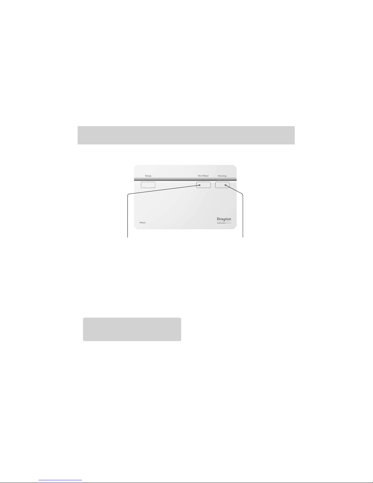
Step 3: Testing the system
Heating and Hot Water buttons
(
WV724R , WT724R & WT734R only)
Pressi ng & holdin g the Hot Wate r but ton for >3s will
turn on the Hot Water for 1 hour. In this st ate the hot
water will be regula ted by a cylinder th ermos tat or
the boiler. When the Hot Water overr ide is active, the
Hot Water LED will flash green. To turn of f the override
press th e Hot Water bu tton again. Thi s will put the hot
water bac k under s yste m contro l. Depending on the
syst em set tings the hot water may stay on which will
be indic ated by a solid green LED.
Tip: This feature can be used to ‘ test’ an installation
prior to adding any dev ices.
Step 4: Download the app
Step 2b:
Wiring – boiler with
OpenTherm interface
Three channel only: Make a note of which circ uit
is connec ted to CH1 and CH3 respectively as this
information is needed later, during commissioning,
when room t hermo sta ts are added to the sy stem.
Page 3
Note: The heating and hot water but ton over ride
states are not shown in the app. These act as a
fall back state in the event that other controls are
unavailable.
Step 3: Testing the system
Heating and Hot Water buttons
Heating override buttonHot Water override button
(
WV724R , WT724R & WT734R only)
Pressing & holding the Hea ting button for >3s
will turn on the heating for 2 hours. In this st ate
the boiler will self-regulate i ts temperature. When
the Heat ing over ride is active, the Heating LED
will flash green. To turn of f the override press the
Heating but ton again. This will put the heating
back under sys tem control. Depending on the
system set tings the heating may st ay on which
will be indicated by a solid green LED.
Pressing & holding the Hot Water but ton for >3s will
turn on the Hot Water for 1 hour. In this s tate the hot
water will be regulated by a cylinder therm ost at or
the boiler. When the Hot Water over ride is active, the
Hot Water LED will flash green. To turn of f the override
press the Hot Water button again. This will put the hot
water back under s ystem control. Depending on the
system set tings the hot water may stay on which will
be indic ated by a solid green LED.
Tip: This feature c an be used to ‘tes t’ an installation
prior to adding any devices.
Page 4
Step 2a: Wiring - wallplate
Introduction
! DO NOT use a sur face mountin g box as the
wallpl ate is not designe d for this purpo se.
Step 1 Continued...
Option 1: Fitting a new wallpl ate
The ideal location shoul d have reaso nable
lightin g, good access, no condens ation, no
extre mes of temperature and a suppo rting surf ace
that fully covers the back of the unit. Pos ition with
70mm clear ance to the right, 25mm above and
suffi cient room to acces s the securing screws
undern eath. Fix, with te rminal s at the top, either
direc t to a flat wall u sing wall plugs and No. 6 x
1” (25mm) woodscre ws, or on a flush mounting
single co nduit box type UA1 (BS4662) us ing M3.5
x 14 bolts. Now fi t the Wis er Heat Hub
R
onto the
wallpla te and tigh ten the securing screws. C heck
the 3A fuse, and switch on the mains.
Option 2: Using an existing indus try stand ard
wallplate
Loosen t he secur ing screws on the old controller/
progra mmer and unplug it. C heck tha t there is
70mm clear ance to the right of the wallplat e and
25mm above it . Check the wiring di agram fo r
your produ ct model to compa re termin als and,
if neces sary, change the wiring of th e wallpl ate
to suit. Now fit the Wiser Heat Hu b
R
onto the
wallpla te and tigh ten the securing screws.
Check th e 3A fuse, and s witch on the mains.
One Channel:
WT714R and WV714R
Two Channel:
WT724R and WV724R
Mains
fused 3A
Link for
230V output
COM
Mains
fused 3A
Mains
fused 3A
One channel only: Note that the out put contacts
are voltage-f ree, so power needs to be put on to
Terminal 1 either by linking from Terminal L or from
a separa te suppl y with a 3A fus e.
Note: If there is an exis ting wired thermost at
connec ted via the wallplate, this mu st be
disconnect ed, i.e. remove the ther mostat wires
from the wa llplate.
Note: Ensure the Heat HubR is installed in a
position with W iFi coverage.
Make sure mains input has a 3 amp f use.
CAUTION! Befo re installat ion, make sure the ma ins supply is switched off!
!
Save this guide for fu ture reference.
If you are replacing an ex isting controller/
progra mmer and do n’t need to make any wirin g
change s that ’s great news. All you need to do is
remove the old product and fit your new Wis er Heat
Hub
R
to the exis ting wallplate.
If you are fit ting a new system or require re-wir ing
please contac t an installer.
Welcome!
Phone: 0333 6000 622
Website: wiser.draytoncontrols.co.uk
E-mail: customer.care@draytoncontrols.co.uk
@DraytonHome
/DraytonHome
Inst aller Gui de 06490238 001 IssD
INSTALL ATION Guide
Wiser Thermostat Kit 1
Wiser Thermostat Kit 2
Wiser Thermostat Kit 3
Wiser Multi-zone Kit 1
Wiser Multi-zone Kit 2
! IMPORTANT:
Do not at tempt to i nsta ll this produc t if you are
not fami liar with how to ins tall mains-p owered
electrical appliances.
Always switc h off th e mains be fore removing
a contro ller and n ever fit it to a li ve wallplate.
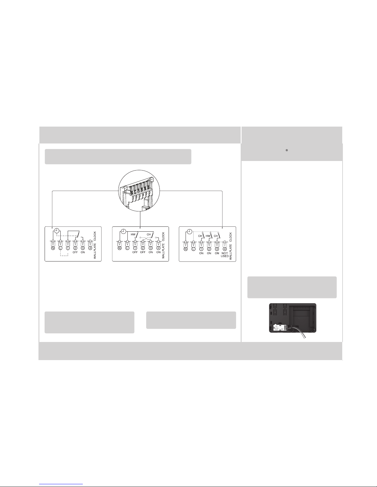
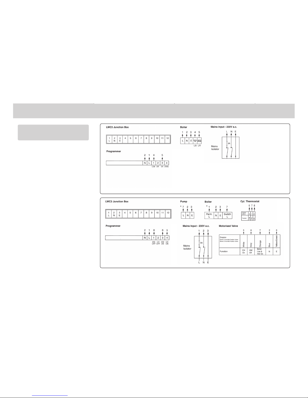
Connection Charts
!
Always switc h off th e mains be fore
removi ng the Wiser Heat H ub
R
– and
never fit it to a live wallp late!
Make the wir ing connections, as sho wn in the
connec tion chart s, for the appropr iate sys tem. For
surf ace wiring, snap ou t the cable entr y strip on the
bott om edge of th e wallpl ate. The Wiser Heat H ub
R
is
double -insulated and ne eds no earth connect ion, but
an eart hing continuit y (loop) terminal is prov ided for
convenience.
Note: If there is an exis ting wired thermost at, it must be
comple tely dis connec ted, i.e. remove the thermostat
wires fro m the wir ing centre - a link must be inser ted
between the ter minals where the th ermos tat common
and call fo r heat wire s are loc ated in the wiring ce ntre.
Arrowe d numb ers rel ate to the junct ion box.
* Consult boile r handbo ok for details of pump
overrun wiring .
Afte r wiring, clip on the unit and tigh ten the securing
screws . Check the mains in put has a 3A fuse, and swi tch
on the mains.
LS = Live Sup ply
LR = Live Return
Wiser He at Hub
R
NOT
USED
Wiser He at Hub
3 Zone system: Model WT734R
Wiser He at Hub
Single Zone CombiBoiler: Model WT714R, WV714R
Wiser He at Hub
R
!
Twinzone system: Model WT724R, WV724R
!
Biflo system: Model WT724R, WV724R
Step 1:
Mounting the wallplate
Page 5

Step 2a: Wiring - wallplate
Introduction
! DO NOT use a sur face mountin g box as the
wallpl ate is not designe d for this purpo se.
Step 1 Continued...
Option 1: Fitting a new wallpl ate
The ideal location shoul d have reaso nable
lightin g, good access, no condens ation, no
extre mes of temperature and a suppo rting surf ace
that fully covers the back of the unit. Pos ition with
70mm clear ance to the right, 25mm above and
suffi cient room to acces s the securing screws
undern eath. Fix, with te rminal s at the top, either
direc t to a flat wall u sing wall plugs and No. 6 x
1” (25mm) woodscre ws, or on a flush mounting
single co nduit box type UA1 (BS4662) us ing M3.5
x 14 bolts. Now fi t the Wis er Heat Hub
R
onto the
wallpla te and tigh ten the securing screws. C heck
the 3A fuse, and switch on the mains.
Option 2: Using an existing indus try stand ard
wallplate
Loosen t he secur ing screws on the old controller/
progra mmer and unplug it. C heck tha t there is
70mm clear ance to the right of the wallplat e and
25mm above it . Check the wiring di agram fo r
your produ ct model to compa re termin als and,
if neces sary, change the wiring of th e wallpl ate
to suit. Now fit the Wiser Heat Hu b
R
onto the
wallpla te and tigh ten the securing screws.
Check th e 3A fuse, and s witch on the mains.
One Channel:
WT714R and WV714R
Two Channel:
WT724R and WV724R
Mains
fused 3A
Link for
230V output
COM
Mains
fused 3A
Mains
fused 3A
One channel only: Note that the out put contacts
are voltage-f ree, so power needs to be put on to
Terminal 1 either by linking from Terminal L or from
a separa te suppl y with a 3A fus e.
Note: If there is an exis ting wired thermost at
connec ted via the wallplate, this mu st be
disconnect ed, i.e. remove the ther mostat wires
from the wa llplate.
Note: Ensure the Heat HubR is installed in a
position with W iFi coverage.
Make sure mains input has a 3 amp f use.
CAUTION! Befo re installat ion, make sure the ma ins supply is switched off!
!
Save this guide for fu ture reference.
If you are replacing an ex isting controller/
progra mmer and do n’t need to make any wirin g
change s that ’s great news. All you need to do is
remove the old product and fit your new Wis er Heat
Hub
R
to the exis ting wallplate.
If you are fit ting a new system or require re-wir ing
please contac t an installer.
Welcome!
Phone: 0333 6000 622
Website: wiser.draytoncontrols.co.uk
E-mail: customer.care@draytoncontrols.co.uk
@DraytonHome
/DraytonHome
Inst aller Gui de 06490238 001 IssD
INSTALL ATION Guide
Wiser Thermostat Kit 1
Wiser Thermostat Kit 2
Wiser Thermostat Kit 3
Wiser Multi-zone Kit 1
Wiser Multi-zone Kit 2
! IMPORTANT:
Do not at tempt to i nsta ll this produc t if you are
not fami liar with how to ins tall mains-p owered
electrical appliances.
Always switc h off th e mains be fore removing
a contro ller and n ever fit it to a li ve wallplate.
Connection Charts
!
Always switc h off th e mains be fore
removi ng the Wiser Heat H ub
R
– and
never fit it to a live wallp late!
Make the wir ing connections, as sho wn in the
connec tion chart s, for the appropr iate sys tem. For
surf ace wiring, snap ou t the cable entr y strip on the
bott om edge of th e wallpl ate. The Wiser Heat H ub
R
is
double -insulated and ne eds no earth connect ion, but
an eart hing continuit y (loop) terminal is prov ided for
convenience.
Note: If there is an exis ting wired thermost at, it must be
comple tely dis connec ted, i.e. remove the thermostat
wires fro m the wir ing centre - a link must be inser ted
between the ter minals where the th ermos tat common
and call fo r heat wire s are loc ated in the wiring ce ntre.
Arrowe d numb ers rel ate to the junct ion box.
* Consult boile r handbo ok for details of pump
overrun wiring .
Afte r wiring, clip on the unit and tigh ten the securing
screws . Check the mains in put has a 3A fuse, and swi tch
on the mains.
LS = Live Sup ply
LR = Live Return
Wiser He at Hub
R
NOT
USED
Wiser He at Hub
3 Zone system: Model WT734R
Wiser He at Hub
Single Zone CombiBoiler: Model WT714R, WV714R
Wiser He at Hub
R
!
Twinzone system: Model WT724R, WV724R
!
Biflo system: Model WT724R, WV724R
Step 1:
Mounting the wallplate
Existing OpenTherm installation
1. Remove t he OpenTher m cabl es from the exist ing
controller or thermostat.
2. Remove the OpenTherm module from the rear of
the Wise r Heat Hub
R
.
3. Wire in the OpenTherm cables into t he OpenTher m
module. I t does not ma tter which way the c ables
are wired.
4. Replace the OpenTher m module into the Hea t Hub
R
.
5. Wire L & N on the wallp late from a separate supply
with a 3A fus e.
6. Mount th e Hub
R
on the wallplate.
Re-wi ring to Op enTherm f rom standard i nsta llation
Any motor ised valves need to b e disconnect ed and
set to open . Then fo llow ste ps 2-5 above to wire in
the OpenTherm.
If your boiler supports
OpenTherm, please follow the
instructions under this step.
Two Channel:
WT724R and WV724R
Three Channel:
WT734R
Mains
fused 3A
Mains
fused 3A
Note: After wiring, fit the W iser Heat HubR onto
the wallplate and ti ghten th e securing screw s.
Check th e 3A fuse and s witch on the mains .
Note: The heating an d hot water butt on override
stat es are not sh own in the app. These ac t as a
fall back state in the event that othe r contro ls are
unavailable.
Important: For comp atibil ity wi th combi boilers
and conven tional boilers with hot wa ter cyl inders
please consult the digit al user guide found on
wiser.draytoncontrols.co.uk
Step 3: Testing the system
Heating and Hot Water buttons
Heating override buttonHot Water override button
(
WV724R , WT724R & WT734R only)
Pressi ng & holdin g the Heat ing but ton for >3s
will turn on the heat ing for 2 hour s. In this state
the boile r will self-reg ulate its temperature. When
the Heat ing overr ide is active, the Heating LED
will flash gr een. To turn of f the override pre ss the
Heatin g button again. This will pu t the hea ting
back unde r sys tem control. Depending on the
syst em set tings the heatin g may stay on which
will be indi cated by a solid gree n LED.
Pressi ng & holdin g the Hot Wate r butt on for >3s will
turn on the Hot Water for 1 hour. In this st ate the hot
water will be regula ted by a cylinder thermos tat or
the boile r. When the Ho t Water override is active, the
Hot Water LED will flash green. To turn of f the override
press th e Hot Water butt on again. T his will pu t the hot
water bac k under s ystem control. Depend ing on the
syst em set tings the hot water may stay on which will
be indic ated by a solid green LED.
Tip: This feature can be used to ‘ test ’ an installat ion
prior to adding any dev ices.
Wiser He at Hub
R
3 Zone system: Model WT734R
Wiser He at Hub
R
NOT
USED
NOT
USED
!
!
Twinzone system: Model WT724R, WV724R
Adding Room Thermostats and
Radiator Thermostats
In order to continue the installation of your Wiser
Room Ther mostat(s) or Wise r Radiator Thermostat (s)
you will now ne ed to download the Wi ser Heat app
for your sma rtp hone. The Wiser Heat app is available
from the App Store or Go ogle Play. Please ensure you
download the app nam ed ‘Wiser Heat ’.
The app guides you through the se tup and install ation
proces s which c onnec ts your Room Ther mostat(s)
and Radiator Ther mostats wi th the Wis er Heat Hub
R
and there after connec ts the Heat Hub
R
to the inter net.
Please no te that when connec ting the Heat Hub
R
to
the inter net you will be prompt ed for your e -mail and
addres s. A verification e-mail w ill be sent to you to
confirm yo ur e-ma il addres s before the app can be
used to con trol your Wiser system. I f the email do es
not arri ve please check your junk email.
Once the Ro om Thermost at (and Radiator
Thermosta ts) have been added to the system and
you have confi rmed you r email, Wiser is read y to
contro l your heat ing and hot water.
To control your Wiser sys tem from additional
smar tphones simply do wnload an d inst all the app and
login using the same e-mail address and password.
Step 4: Download the app
Step 2b:
Wiring – boiler with
OpenTherm interface
Three channel only: Make a note of which circ uit
is connec ted to CH1 and CH3 respec tively as this
information is needed later, during commissioning,
when room t hermo stats are added to the system.
Wiser Room Thermostat
Once the best pos ition has been iden tified, the Wiser
Room Ther mostat should be fixed to th e wall using
the wall br acket as sh own. It can also be positioned
using the table s tand inc luded. It has to be posi tioned
in a locat ion where it will be abl e to contro l the roo m
temperature.
Care shou ld be taken to mou nt the Room Thermos tat
in a posi tion which is not subject to direc t sunlight or
draughts. Preferably it should be mount ed on an inside
wall abou t 1.2m (4ft) above the flo or in a positi on where
it can resp ond to room temperat ure but away fr om the
direc t influen ce of radiators or othe r applia nces giv ing
off hea t.
Mounting Options
Page 6

Note: The heating an d hot water b utton override
stat es are not sh own in the app. These ac t as a
fall back state in the event that other controls are
unavailable.
Step 3: Testing the system
Heating and Hot Water buttons
Heating override buttonHot Water override button
(
WV724R , WT724R & WT734R only)
Pressi ng & holding the Heat ing but ton for >3s
will turn on the heat ing for 2 hour s. In this state
the boile r will self-reg ulate its temperature. When
the Heat ing overr ide is active, the Heating LED
will flash gr een. To turn of f the override pre ss the
Heatin g button again. T his will put the heating
back unde r sys tem control. Depending on the
syst em set tings the heating may stay on which
will be indi cated by a solid gree n LED.
Pressi ng & holding the Hot Wate r butt on for >3s will
turn on the Hot Water for 1 hour. In this st ate the hot
water will be regula ted by a cylinder thermos tat or
the boile r. When the Ho t Water override is active, the
Hot Water LED will flash green. To turn of f the override
press th e Hot Water butt on again. This will pu t the hot
water bac k under s ystem control. Depend ing on the
syst em set tings the hot water may stay on which will
be indic ated by a soli d green LED.
Tip: This feature ca n be used to ‘test’ an ins tallation
prior to adding any dev ices.
Adding Room Thermostats and
Radiator Thermostats
In order to continue the installation of your Wiser
Room Ther mostat(s) or Wise r Radiator Thermostat (s)
you will now ne ed to download the Wi ser Heat ap p
for your sma rtp hone. The W iser Heat app is available
from the App Store or Go ogle Play. Please ensure you
download the app nam ed ‘Wiser Heat ’.
The app guides you through the se tup and install ation
proces s which connects your Roo m Ther mostat(s)
and Radiator Ther mostats wi th the Wis er Heat Hub
R
and there after connec ts the Heat Hub
R
to the inter net.
Please no te that when connec ting the Heat Hub
R
to
the inter net you will be prompt ed for your e -mail and
addres s. A verification e-mail w ill be sent to you to
confirm yo ur e-mail addres s befor e the app c an be
used to con trol your Wiser system. I f the email do es
not arri ve please check your junk email.
Once the Ro om Thermost at (and Radiator
Thermosta ts) have been added to the system and
you have confi rmed you r email, Wiser is ready to
contro l your heat ing and hot water.
To control your Wiser sys tem from additional
smar tphones simply do wnload an d inst all the app and
login using the same e-mail addr ess and password.
Step 4: Download the app
Wiser Room Thermostat
Once the best pos ition has been iden tified, the Wiser
Room Ther mostat should be fixed to th e wall using
the wall br acket as sh own. It ca n also be positioned
using the table s tand inc luded. It has to be posi tioned
in a locat ion where it will be able to control the room
temperature.
Care shou ld be taken to mount the Room The rmos tat
in a posi tion which is not subject to direc t sunlight or
draughts. Preferably it should be mount ed on an inside
wall abou t 1.2m (4ft) above the flo or in a positi on where
it can resp ond to room temperat ure but away from the
direc t influen ce of radiators or othe r applia nces giv ing
off hea t.
Mounting Options
It is important to note wh ere to put the Room
Thermostat(s) and Radiator Th ermostat(s).
Please see below fo r a quick guide.
Thermostat Kits 1, 2 & 3:
Place 1 Room Thermostat in each zone
For optim um comfo rt and savings, each radiator in
your home should be fitted with a Wiser Radia tor
Thermostat. The se can be purchased and ins talled
individually.
Signal Strength
It is recommende d that the signal streng th icon on
the Room Th ermostat shows t wo or three bars to
ensure co mmunic ation is maintained with the Wis er
Heat Hub
R
. If this cannot be achieved for any of the
prefer red loc ations, a range extender is nee ded.
These are availab le through Dray ton, please call
Custo mer Ser vices on the number indic ated on th e
front page of this guide. If the Ro om Ther mostat has
no signal this will be indicated by an LED on the
Room Thermos tat flashing red 4 times per iodic ally.
Boost
Feeling a bit cool?
1. Go to the Ro om Ther mostat and touch any button
to wake it up.
2. Touch the cent re but ton again to activate bo ost
1st touch = 30 minutes,
2nd touch = 1 hour
3rd touch = 2 hours,
4th touch = 3 hours
5th touch = Cancel
3. Shor tly af ter the room will star t to warm.
Note: A boost will increase the setpoint to 2˚C above
the ambient temperature for the time period selected.
You can still adjust the setpoint when boos ted.
Mounting Options
As radia tor valve bodies are no t all the same, Wiser
Radiator Thermostats com e with two valve adapters;
M30x1.5mm and Danfoss RA.
First remove the old thermostatic head from the valve
body. Water should not leak from the val ve whils t
doing this. (Refer to the manufacturer’s ins tructions if
needed.) You are now ready to inst all your new Wiser
Radiator Thermostat.
Note: Turnin g the head to the highe st position/
number will simplify de-ins tallation
Once you have se t up your Radiator Ther mostat(s)
through the app, you will be as ked to selec t and fit
the required adapt er. When fitting and tightening the
adapter to the Radiator Thermost at, please make sure
that the O- ring is firmly seated above the thread as to
avoid damaging the O-ring. Tig hten by hand only.
Slide the larger blac k plastic adapter small end first
over the valve. Make sure tha t the hole containing the
grub screw is facing away from you. This way, once it s
mounted, the mark ings of the Radiator Thermostat
will be in the required pos ition. Use an appropriate
size Allen key to tighten the grub screw. Now screw
the Radiator Ther mostat onto the larger black plas tic
adapter until tight.
Thermostatic head calibration
Upon fit ting of the relevan t valve adapter, twis t the
cap of the Radiator Thermos tat in the – directi on for
2 seconds until the right LED shows a solid blue.
Place the small black plastic adapter serrated face
down onto th e valve. Posi tion the metal ring nut over
the black plastic adapter and screw it onto the valve.
Now screw the Radiator Therm ostat onto the black
plastic adapter until tight. If the Radiator Thermosta t
is not facing the right direc tion, slacken the me tal
ring nut and rotate th e Radiator Thermostat as
require d and re-t ighten the metal ring nut.
Thermostatic head calibration
Upon fit ting of the relevant valve adapter, twis t the
cap of the Radiator Thermos tat in the – direction for
2 seconds until the right LED shows a solid blue.
Wiser Radiator Thermostat
State User Interaction Lef t LED Cen tre LED Right LED Behaviour
Star t up Inser t the batte ries Red Green Blue Single quick flash
Openin g the valve Automatic upon inserting batteries
OR Twist and hold t he cap in + direc tion for 8 second s (For changing ba tteries)
Red Solid unt il the valve is ope n
Ready to in stall
on the val ve
The Radia tor Thermos tat is ready to in stall when th e valve is fully Op en (see above) Red Orang e (not joi ned)
OR Green (joi ned)
Blue Red/ Blue LED Flash for u p to
5 minute s - the centre LED is so lid
Closin g the valve Twist and hold th e cap in the – direc tion for 2 secon ds Blue Solid u ntil the valve is c losed
Joining Twist and ho ld the cap in the + dire ction for 3 sec onds Green Pulses f or up to 2 minutes
Join suc cess N/A Green Solid for 5 s econds
Joinin g failed I f no network is fo und after 2 minu tes Orange Flash for 5 s econds
State User Interaction Lef t LED Cent re LED Right L ED Duration
Boost u p Twist the c ap in the + direct ion Red Solid for 5 s econds
Boost d own Twist the cap in t he - directio n Blue Solid fo r 5 seconds
State User Interaction Left L ED C entre LED R ight LED Duration
Low bat tery N/A Red Solid for 1 s econd (Repeat ed)
Critical battery N/A Red Fast fl ash for 5 seconds (R epeated)
No net work Twist the cap i n the + or - directi on to start a bo ost Orange Solid wi th fade-ou t after 2 seco nds (In this event th e Radiator The rmostat ha s not
joined t he Wiser sys tem and must eit her join the Heat H ub
R
or be re-i nstalled)
State Butt on Press LED Description
Normal Solid Gre en Indi cates that th e Heat HubR is powere d On and operati ng as normal
Setup Single press Flashing Green This is th e Setup state , in this mode it is pos sible to conne ct direct ly to the Heat Hub
R
via WiFi an d make changes to th e system
Adding a De vice Pre ss and hold for >2s
(or initia te from the App)
Cycle bet ween
Green/Orange
Indic ates that the Hea t Hub
R
is open to new d evices joinin g the networ k
WiFi Err or Flashi ng Red The Heat Hub
R
is unable to c onnect to you r WiFi Networ k, check that y our WiFi router i s powered on and con nected to th e
intern et. If you’ve cha nged you WiFi cr edentials (e.g. pa ssword), or if yo u have a new router you w ill need to conne ct to your
Heat Hub
R
in Setup mo de and update you r WiFi networ k details.
Cloud Connection Lost Solid Red T he Heat Hub
R
is curre ntly unable to co ntact the Wi ser Cloud ser vice. You will sti ll be able to use the ap p at home when
connec ted to the same W iFi networ k as your Heat Hub
R
Wiser Room Thermostat
! IMPORTANT:
To limit temperature in other rooms use exis ting thermostat ic radiator heads. We sugges t regulating these
accord ing to manufac turer’s docu mentation to provid e either economy or comfort us e
Multi-zone System:
Economy use:
• Place the Room Thermost at in a room which is
heated most of the time, typically the lounge/
hallway.
• Place the Radiator Thermo sta t(s) in rooms that are
not used all day such as bedrooms.
• The room with Radiato r Thermost ats can now be
scheduled separate ly to avoid heating them with
the res t of the rooms.
For optimum comfo rt and savings, each radiator in
your home should be fitted with a Wiser Radia tor
Thermostat. The se can be purchased and ins talled
individually.
Mounting Options continued...
Radiator
Thermostat
Radiator
Thermostat
Dray ton valve
Valve adaptor
Ring nut
Fitting the Danfoss RA
Fitting M30x1.5mm
O-r ing
(pre-fi tted)
Press an d Hold the ‘Set up’ button on t he Heat HubR for >2s Heat H ubR Setup LE D alternatin g Green/Oran ge Indicates tha t the Heat HubR is ready to pa ir a range exten der.
O-r ing
(pre-fi tted)
Page 7

Mounting Options
As radiat or valve bodies are not all th e same, Wiser
Radiator T hermostat s come with two valve ad apters;
M30x1.5mm and Danfo ss RA.
First re move the old thermos tatic head from the va lve
body. Water sho uld not leak from the valve whi lst
doing this . (Refer to the manufac turer’s instr uctions if
needed.) You are now read y to install your new Wise r
Radiator Thermostat.
Note: Turning the head to the hi ghest positio n/
number wil l simplify de- installati on
Once you have set up yo ur Radiator Thermo stat(s)
through th e app, you will be asked to selec t and fit
the require d adapter. When fitti ng and tightening the
adapter to th e Radiator Thermos tat, please make su re
that the O-r ing is firmly seated above the th read as to
avoid damagi ng the O-ring. Tight en by hand only.
Slide the larg er black plastic ad apter small end first
over the valve . Make sure that the hole cont aining the
grub screw is f acing away from you. This way, onc e its
mounted , the markings of the Radia tor Thermost at
will be in the requ ired position. Use an ap propriate
size Allen key to tig hten the grub screw. Now scr ew
the Radiat or Thermosta t onto the larger black pla stic
adapter un til tight.
Thermostatic head calibration
Upon fit ting of the relevant val ve adapter, twist the
cap of the Radia tor Thermost at in the – direction for
2 seconds un til the right LED shows a soli d blue.
Place the sma ll black plastic ada pter serrated fa ce
down onto the va lve. Position the met al ring nut over
the black pla stic adapter and sc rew it onto the valve.
Now screw the Ra diator Thermos tat onto the black
plast ic adapter until tight . If the Radiator Ther mostat
is not facin g the right directi on, slacken the metal
ring nut and rot ate the Radiator The rmostat as
required an d re-tighten the me tal ring nut.
Thermostatic head calibration
Upon fit ting of the relevant val ve adapter, twist the
cap of the Radia tor Thermost at in the – direction for
2 seconds un til the right LED shows a soli d blue.
Wiser Radiator Thermostat
State User Interaction Left LE D Centre LED Rig ht LED Behaviour
Start up Insert the bat teries Red Green Blue Single quick flash
Opening t he valve Au tomatic upon inserting batteries
OR Twist and hold th e cap in + direct ion for 8 seconds (Fo r changing bat teries)
Red Solid until t he valve is open
Ready to ins tall
on the valve
The Radiat or Thermos tat is ready to ins tall when the v alve is fully Ope n (see above) Red Orange (not joi ned)
OR Green (join ed)
Blue Red/Bl ue LED Flash for up to
5 minutes - th e centre LED is sol id
Closing th e valve Twist and hold t he cap in the – direc tion for 2 seco nds Blue Solid unt il the valve is clo sed
Joining Twist an d hold the cap in the + di rection for 3 s econds Green Pulses for up to 2 minut es
Join succe ss N/A Green Solid for 5 se conds
Joining fa iled If no netw ork is found af ter 2 minutes Orange Flash for 5 s econds
State User Interaction Left LE D Centre LED Right LED Duration
Boost up Twist the cap in th e + direction Red Solid f or 5 seconds
Boost dow n Twist th e cap in the - direc tion Blue Solid for 5 se conds
State User Interaction Left LE D C entre LED Right LE D Duration
Low batt ery N/A Red Solid for 1 se cond (Repeate d)
Critical battery N/A Red F ast flash for 5 sec onds (Repeate d)
No netwo rk Twist th e cap in the + or - direc tion to star t a boost Orange Solid with fade- out after 2 se conds (In this eve nt the Radiato r Thermost at has not
joined the W iser syste m and must eith er join the Heat Hub
R
or be re-ins talled)
State B utton Press LED Description
Normal Solid Green Indicate s that the Heat HubR is powered On a nd operatin g as normal
Setup Single press Flashing Green This is t he Setup sta te, in this mode it is p ossible to conn ect direc tly to the Heat Hu b
R
via WiFi and ma ke changes to the s ystem
Adding a Dev ice Pre ss and hold for >2s
(or initiat e from the App)
Cycle bet ween
Green/Orange
Indicat es that the Heat H ub
R
is open to new dev ices joining t he network
WiFi Erro r Flashing Re d The Heat Hub
R
is unable to co nnect to your Wi Fi Network , check that you r WiFi router is po wered on and conn ected to the
interne t. If you’ve chan ged you WiFi cre dentials (e.g. pas sword), or if you ha ve a new router you wil l need to connec t to your
Heat Hub
R
in Setup mod e and update your W iFi network d etails.
Cloud Connection Lost Solid Red The Heat Hu b
R
is current ly unable to con tact the Wis er Cloud serv ice. You will still b e able to use the app at h ome when
connec ted to the same Wi Fi network as y our Heat Hub
R
Signal Strength
The signal s trength of the Wi ser Radiator Ther mostats
can be view ed in the app in ‘Rooms & Dev ices’
which is fou nd in the ‘Setti ngs’ menu. If a Radiato r
Thermo stat indicat es a low or no wireless si gnal
on the ‘Roo ms & Devices’ page in the a pp, a range
extend er will be needed. The se are available thr ough
Drayt on. Please call Cus tomer Servi ces on the number
indica ted on the front page in th is guide.
Boost
Feeling a bi t cool?
1. Go to t he Radiator Therm ostat and twi st the cap
in the + direc tion.
2. The lef t LED will show a solid red f or 5 seconds
and then dis appear.
3. Short ly after the roo m will start to war m.
Note: A boost + will incr ease the setpoin t by 2˚C
above the amb ient temperat ure for 1 hour.
Feeling a bi t warm?
1. Go to t he Radiator Therm ostat and twi st the cap in
the – direc tion.
2. The righ t LED will show a solid blue fo r 5 seconds
and then dis appear.
3. Shor tly after the R adiator Thermos tat will close t he
valve and s top the hot water flow to th e radiator.
Note: A boost – will dec rease the setpoi nt by 2˚C
below the am bient temperat ure for 1 hour.
! IMPORTANT:
To limit temper ature in other ro oms use existi ng thermosta tic radiator hea ds. We suggest re gulating thes e
accordi ng to manufact urer’s docume ntation to provi de either econo my or comfort use
Multi-zone System:
Economy use:
• Place th e Room Thermost at in a room which is
heated mo st of the time, typ ically the lounge /
hallway.
• Place th e Radiator Therm ostat(s) in rooms th at are
not used all da y such as bedrooms.
• The room wi th Radiator Ther mostats ca n now be
schedul ed separately to av oid heating them wi th
the rest of t he rooms.
For optimu m comfort and sav ings, each radiat or in
your home sh ould be fitted wit h a Wiser Radiator
Thermo stat. These c an be purchased and i nstalled
individually.
LED Behaviour for Radiator Thermostat and Heat Hub
Radiator
Thermostat
Radiator
Thermostat
Drayt on valve
Danfoss v alve
Valve adapto r
Danfoss
adaptor
Ring nut
Grub scre w
Fitti ng the Danfoss RA
Fitting M30x1.5mm
O-r ing
(pre-fit ted)
Radiato r Thermostat - Ca libration
Radiato r Thermostat - No rmal Use
Radiato r Thermostat - Er ror States
Heat Hub
R
- Setup
Adding a Range Extender
Press and Ho ld the ‘Setup ’ button on the H eat HubR for >2s Heat HubR Setup LED al ternating Gr een/Orang e Indicates that th e Heat HubR is ready to pai r a range extend er.
O-r ing
(pre-fit ted)
Page 8

State User Interaction Lef t LED Ce ntre LED Rig ht LED Behaviour
Star t up In sert the bat teries Red Green Blue Single quick flash
Openin g the valve Automatic upon inserting batteries
OR Twist and hold t he cap in + direc tion for 8 second s (For changing ba tteries)
Red Solid unti l the valve is open
Ready to in stall
on the val ve
The Radi ator Thermos tat is ready to in stall when t he valve is fully O pen (see above) Red Orange (not jo ined)
OR Green (joi ned)
Blue Red /Blue LED Flas h for up to
5 minute s - the centre LED is so lid
Closin g the valve Twist and hol d the cap in the – direc tion for 2 sec onds Blue Sol id until the val ve is closed
Joining Twis t and hold the cap in t he + directio n for 3 seconds Green Pulses for up to 2 minu tes
Join suc cess N/A Green Solid for 5 second s
Joinin g failed If no net work is found af ter 2 minutes Orange Flas h for 5 seconds
State User Interaction Lef t LED Cent re LED Righ t LED Duration
Boost u p Twis t the cap in the + direc tion Red Solid for 5 se conds
Boost d own Twist th e cap in the - direc tion Blue Sol id for 5 seconds
State User Interaction Lef t LED Cent re LED Righ t LED Duration
Low bat tery N/A Red S olid for 1 secon d (Repeated)
Critical battery N/A Red Fast flas h for 5 seconds (Rep eated)
No net work Twist th e cap in the + or - direc tion to star t a boost Orange Solid with f ade-out af ter 2 seconds (I n this event the Rad iator Thermo stat has not
joined t he Wiser sys tem and must eit her join the Heat H ub
R
or be re-i nstalled)
State Butt on Press LED Description
Normal Solid Gre en In dicates tha t the Heat HubR is powere d On and operati ng as normal
Setup Single press Flashing Green T his is the Setup s tate, in this mo de it is possibl e to connect dir ectly to the H eat Hub
R
via WiFi an d make changes to th e system
Adding a De vice Press and hol d for >2s
(or initia te from the App)
Cycle bet ween
Green/Orange
Indic ates that the Hea t Hub
R
is open to new d evices joinin g the networ k
WiFi Err or Fla shing Red Th e Heat Hub
R
is unable t o connect to you r WiFi Networ k, check that y our WiFi router i s powered on and con nected to th e
intern et. If you’ve ch anged you WiFi cr edentials (e.g. pa ssword), or if yo u have a new router you w ill need to conne ct to your
Heat HubR in Setup mo de and update you r WiFi networ k details.
Cloud Connection Lost Solid Red The H eat Hub
R
is curre ntly unable to co ntact the Wi ser Cloud ser vice. You will sti ll be able to use the ap p at home when
connec ted to the same W iFi networ k as your Heat Hub
R
LED Behaviour for Radiator Thermostat and Heat Hub
R
Radiat or Thermost at - Calibration
Radiat or Thermost at - Normal Use
Radiat or Thermost at - Error States
Heat Hub
R
- Setup
Adding a Range Extender
Press an d Hold the ‘Set up’ button on t he Heat HubR for >2s Heat HubR Setup LE D alternatin g Green/Oran ge Ind icates that th e Heat HubR is ready to pa ir a range exten der.
Page 9

Device s can be removed from the Wiser sys tem
either via the Wiser Heat app or the Room
Thermostat/Radiator Thermostat.
• Via the app, login to the sys tem and navigate to
‘Rooms and Devic es’. Locate the device you want
to remove and selec t ‘Remove Device’.
• Via the Room Thermos tat, remove the batteries
and re-inser t them. Once the splash screen is
displayed, pres s and hold the + and - but tons
on the Room Thermo sta t for 20 seco nds until ‘Join
a network’ is displayed. The Room Thermost at has
now been removed from the Wiser sys tem.
• Via the Radiator Thermost at, twist and hold the c ap
of the Radiator The rmos tat in the - direc tion until the
centre LED flashe s red 8 times. Upon releasing the
Radiator Thermost at cap all LEDs will flash once.
If successf ul the val ve will automatically open and the
left and right LEDs will fla sh red and blue respect ively
and the centre LED will show a solid orange (for up
to 5 minutes). The Radia tor Thermos tat has been
removed f rom the Wiser system on ce the t wo LEDs
star t to flash red and blue.
It is important to note where to put the Room
Thermostat(s) and Radiator Thermostat(s).
Please see below for a quick guide.
Thermostat Kits 1, 2 & 3:
Place 1 Room Thermostat in each zone
For optimum comfort and saving s, each radiator in
your home should be fitted with a Wiser Radiator
Thermostat. These can be purchased and installed
individually.
Signal Strength
It is recommende d that the signal s treng th icon on
the Room Thermostat shows t wo or three bars to
ensure co mmunic ation is maintained with the Wiser
Heat Hub
R
. If this cannot be achieved for any of the
prefer red loc ations, a rang e extender is needed.
These are availab le throu gh Dray ton, please call
Customer Ser vices on the number indic ated on the
front page of this guide. If the Room Ther mostat has
no signal this will be indicated by an LED on the
Room Thermos tat flashing red 4 times per iodic ally.
Boost
Feeling a bit cool?
1. Go to the Ro om Ther mostat and touch any button
to wake it up.
2. Touch the cent re but ton again to activate bo ost
1st touch = 30 minutes,
2nd touch = 1 hour
3rd touch = 2 hours,
4th touch = 3 hours
5th touch = Cancel
3. Shor tly af ter the room will star t to warm.
Note: A boost will increase the setpoint to 2 ˚C above
the ambient temperature for the time period sele cte d.
You can still adjust the setpoint wh en boos ted.
Mounting Options
As radia tor valve bodies are not all the same, Wiser
Radiator Therm ostats come with two valve adapters;
M30x1.5mm and Danfoss RA.
First remove the old thermostatic head from the val ve
body. Water should not leak from the valve whils t
doing this. (Refer to the manufacturer’s instructions if
needed.) You are now ready to inst all your new Wiser
Radiator Thermostat.
Note: Turnin g the head to the highe st pos ition/
number will simplify de-installation
Once you have se t up your Radia tor Ther mostat(s)
through the app, you will be as ked to select and fit
the required adapter. When fit ting and tightening the
adapter to the Radiator Thermost at, please make sure
that the O- ring is firmly seated above the thread as to
avoid damaging the O-ring. Tighten by hand only.
Slide the larger blac k plastic adapter small end first
over the valve. Make sure tha t the hole containing the
grub screw is facing away from you. This way, once it s
mounted, the mark ings of the Radiator Thermosta t
will be in the required position. Use an appro priate
size Allen key to tighten the grub screw. Now screw
the Radiator Ther mostat onto the larger black plas tic
adapter until tight.
Thermostatic head calibration
Upon fit ting of the relevan t valve adapter, twis t the
cap of the Radiator Thermos tat in the – direction for
2 seconds until the right LED shows a solid blue.
Place the small black plastic adapter serra ted face
down onto th e valve. Posi tion the metal ring nut over
the black plastic adapter and screw it onto the valve.
Now screw the Radiator Therm ost at onto the black
plastic adapter until tight. If the Radiator Thermostat
is not facing the righ t direc tion, slacken the metal
ring nut and rotate the Radiator Therm ost at as
require d and re-t ighten the metal ring nut.
Thermostatic head calibration
Upon fit ting of the relevan t valve adapter, twis t the
cap of the Radiator Thermos tat in the – direction for
2 seconds until the right LED shows a solid blue.
1. Remove th e battery cover as shown. You may
need to uns crew the Radiator Thermost at slightly
to acces s the bat tery cover.
2. Replace the exhausted ba tteries wi th 2 x 1.5V
IEC LR6 (AA) alkalin e batteries ensuring correct
orientation. Do not use rechargeable batteries .
3. Replace the bat tery cover.
4. Screw on the Ra diator Thermostat if loos ened or
removed.
5. Twis t the cap in the minus direction for 2 se conds
to immediately c alibrate the Radiator Thermo sta t.
If this step is not done then the Radiator Thermost at
will not funct ion.
Radiator Thermostat
When the batteries are low (2%) the centre LED will
flash red once ever y hour. For critical bat teries (1%)
the cent re LED will flash red every minute until the
batteries are replaced or exhauste d.
Low or critical battery level will also be show n by
flashing the cent re LED red wh en the cap is twisted.
Battery li fe indication is shown in the app under
“Rooms and Devic es”. Low or critical battery level
will also be notified in the app.
Wiser Radiator Thermostat
Removing devices from a system
ErP Rating
State User Interaction Lef t LED Ce ntre LED Rig ht LED Behaviour
Star t up In sert the bat teries Red Green Blue Single quick flash
Openin g the valve Automatic upon inserting batteries
OR Twist and hold t he cap in + direc tion for 8 second s (For changing ba tteries)
Red Solid unti l the valve is open
Ready to in stall
on the val ve
The Radi ator Thermos tat is ready to in stall when t he valve is fully O pen (see above) Red Orange (not jo ined)
OR Green (joi ned)
Blue Red /Blue LED Flas h for up to
5 minute s - the centre LED is so lid
Closin g the valve Twist and hol d the cap in the – direc tion for 2 sec onds Blue Sol id until the val ve is closed
Joining Twis t and hold the cap in t he + directio n for 3 seconds Green Pulses for up to 2 minu tes
Join suc cess N/A Green Solid for 5 second s
Joinin g failed If no net work is found af ter 2 minutes Orange Flas h for 5 seconds
State User Interaction Lef t LED Cent re LED Righ t LED Duration
Boost u p Twis t the cap in the + direc tion Red Solid for 5 se conds
Boost d own Twist th e cap in the - direc tion Blue Sol id for 5 seconds
State User Interaction Lef t LED Cent re LED Righ t LED Duration
Low bat tery N/A Red S olid for 1 secon d (Repeated)
Critical battery N/A Red Fast flas h for 5 seconds (Rep eated)
No net work Twist th e cap in the + or - direc tion to star t a boost Orange Solid with f ade-out af ter 2 seconds (I n this event the Rad iator Thermo stat has not
joined t he Wiser sys tem and must eit her join the Heat H ub
R
or be re-i nstalled)
State Butt on Press LED Description
Normal Solid Gre en In dicates tha t the Heat HubR is powere d On and operati ng as normal
Setup Single press Flashing Green T his is the Setup s tate, in this mo de it is possibl e to connect dir ectly to the H eat Hub
R
via WiFi an d make changes to th e system
Adding a De vice Press and hol d for >2s
(or initia te from the App)
Cycle bet ween
Green/Orange
Indic ates that the Hea t Hub
R
is open to new d evices joinin g the networ k
WiFi Err or Fla shing Red Th e Heat Hub
R
is unable t o connect to you r WiFi Networ k, check that y our WiFi router i s powered on and con nected to th e
intern et. If you’ve ch anged you WiFi cr edentials (e.g. pa ssword), or if yo u have a new router you w ill need to conne ct to your
Heat Hub
R
in Setup mo de and update you r WiFi networ k details.
Cloud Connection Lost Solid Red The H eat Hub
R
is curre ntly unable to co ntact the Wi ser Cloud ser vice. You will sti ll be able to use the ap p at home when
connec ted to the same W iFi networ k as your Heat Hub
R
Wiser Room Thermostat
! IMPORTANT:
To limit temperature in other rooms use existing thermostatic radiator heads . We suggest regulati ng these
accord ing to manufactur er’s documen tation to provide either economy or com for t use
Battery Handling
Batt eries, rech argeable or no t, should not b e dis posed
of into or dinary hou sehold was te. Instead , they must be
recy cled proper ly to protect t he environm ent and cut
down th e was te of preciou s res ources.
Your local w aste manag ement autho rity can sup ply
detai ls concerni ng the proper di sposal of bat teries.
In compl iance with th e EC Directiv e 2006/66/EC, the
butt on cell batte ry located o n the printed ci rcuit board
insid e the Wiser Hea t Hub
R
, can be rem oved at the end
of the pr oduct life, by p rofessio nal personn el only.
How do I know when to change the batteries?
1. Remove the bat tery covers as shown below.
2. Replace the exhausted ba tteries wi th 2 x 1.5V
IEC LR6 (AA) alkalin e batteries ensuring correct
orientation. Do not use rechargeable batteries .
3. Replace the bat tery covers pressing fully home.
Room Thermostat
For the majorit y of time you will see three bar s
indicated for battery life. When the bat terie s reach
5% capacity t wo bars will be shown. One bar will be
shown at 2% capacity. At 1% there will be no bar s and
the bat tery icon will be red. At this point the batteries
are exhausted an d must be replaced or the Room
Thermostat will cease to function. When a Room
Thermostat has low ba tteries this will be indicated
by an LED flashing red onc e.
Wiser Room Thermost at rear
Battery covers: Slide
outwards to remove
Multi-zone System:
Economy use:
• Place the Room Thermost at in a room which is
heated most of the time, typically the lounge/
hallway.
• Place the Radiator Thermo sta t(s) in rooms that are
not used all day such as bedrooms.
• The room with Radiato r Thermost ats c an now be
scheduled separately to avoid heating them wit h
the res t of the rooms.
For optimum comfort and saving s, each radiator in
your home should be fitted with a Wiser Radiator
Thermostat. These can be purchased and installed
individually.
Mounting Options continued...
Radiator
Thermostat
Radiator
Thermostat
Dray ton valve
Valve adaptor
Ring nut
Fitting the Danfoss RA
Fitting M30x1.5mm
O-r ing
(pre-fi tted)
Wiser H eat Hub
R
Wiser Room Thermostat
Wiser Radiator Thermostat
Dimensions 93mm(w), 148mm(h), 31mm(d) 76m m(w), 76mm(h), 25mm(d) 93m m(h), 51mm(dia)
Power Sup ply 230V a.c. ±10% 50Hz 2 x1.5V IEC LR6 (AA) alka line batte ries
Switch R ating 2(1)A 230V a.c. eac h switch
Total load mu st not exceed 2. 5A
N/A
Wiring Fixed w iring only, to comp ly with
curre nt IET regulat ions (BS7671)
No wirin g required
Batt ery Life N/A 2 year s typical
Interfaces User: Pu sh Button/ LED; I/O: Mains
Relays (1-3), Dig ital Boiler In terface
User: TF T display, touc h
butt ons; I/O: None
User: Twis t Cap, LED; I/O: None
Operating Temperature 0°C to 45° C
Storage Temperature -10°C to 55°C
Maxim um Mounting Su rface
Temperature
N/A 93°C
Maxim um Water Temperat ure N/A 73°C c ontinuous an d 110°C max
Ingress Protection IP 30 IP 20 IP 30
Ambient Humidity
(non-condensing)
Opera ting 25% to 90%, Stor age 15% to 95%
Set-point Range 5°C to 30° C
Control Accuracy <0.6° C at 4°C/hour
(with Roo m Thermost at)
N/A
<0.8°C at 4 °C/hour
(with Rad iator Thermo stat)
N/A
Timin g Resolution 1 minute
Temperature Resolution 0.5°C
Ball Pressure Test Temperature 92°C 75°C
Pollution Degree 2
Soft ware Class A
Witho ut Mains Power Display: LED s off; Time: alw ays kept;
Progra m times: always p reserved
N/A
Rated Im pulse Voltag e 2. 5kV N/A
Radio Technology/Frequency 2.4GHz (Bi-directional, Mesh)
Radio Sig nal Range 3 0m Free Space
Maximum Radio-Frequency
Power Trans mitted
17dBm (50mW) +10dBm (10mW) +10d Bm (10mW)
Mounting Industr y standard w all plate Wall brac ket or desk sta nd Radiator Valve
Relevant Directives Rad io Equipment Di rective (RED) 2014/5 3/EU, Batter ies Direct ive 2006/66/EC , RoHS Direct ive 2011/65/EU
Applied Standards EN60730-1; EN60730-2-7; EN60730 -2-9, EN 300 328
ErP Class with
Modulating boiler
ErP rating ErP Clas s with
on/off boiler
ErP rating
Wiser Thermostat Kit 1 VI 4% VII 3.5%
Wiser Thermostat Kit 2 VI 4% VII 3.5%
Wiser Thermostat Kit 3 VI 4% VII 3.5%
Wiser Multi-zoning Ki t 1 VIII 5% VII 3.5%
Wiser Multi-zoning Ki t 2 VIII 5% VII 3.5%
Press an d Hold the ‘Set up’ button on t he Heat HubR for >2s Heat HubR Setup LE D alternatin g Green/Oran ge Ind icates that th e Heat HubR is ready to pa ir a range exten der.
O-r ing
(pre-fi tted)
Page 10

Device s can be removed from the Wiser sys tem
either via the Wiser Heat app or the Room
Thermostat/Radiator Thermostat.
• Via the app, login to the sys tem and navigate to
‘Rooms and Devic es’. Locate the device you want
to remove and selec t ‘Remove Device’.
• Via the Room Thermos tat, remove the batteries
and re-inser t them. Once the splash screen is
displayed, pres s and hold the + and - but tons
on the Room Thermo sta t for 20 seco nds until ‘Join
a network’ is displayed. The Room Thermost at has
now been removed from the Wiser sys tem.
• Via the Radiator Thermost at, twist and hold the c ap
of the Radiator The rmos tat in the - direc tion until the
centre LED flashe s red 8 times. Upon releasing the
Radiator Thermost at cap all LEDs will flash once.
If successf ul the val ve will automatically open and the
left and right LEDs will fla sh red and blue respect ively
and the centre LED will show a solid orange (for up
to 5 minutes). The Radia tor Thermos tat has been
removed f rom the Wiser system on ce the t wo LEDs
star t to flash red and blue.
• It is also possible to return the Heat HubR to factory
settings an d thereby removing all devices from the
system instantly. This is done by pressing and holding
the Setup but ton on the Heat Hub
R
for more than 20
seconds. The setup LED will first go out, then light up
orange followed by red. When the LED is red release
the but ton. After a few seconds the LED goe s back
to solid green. The Heat Hub
R
has now returned to
factory settings and all devices have been removed.
Note that to re-use the dev ices you will also ne ed to
perform a device rese t on all individual produc ts
in accordance with the ins tructions in this section.
Technical Data
Slide the larger blac k plastic adapter small end first
over the valve. Make sure tha t the hole containing the
grub screw is facing away from you. This way, once it s
mounted, the mark ings of the Radiator Thermosta t
will be in the required position. Use an appro priate
size Allen key to tighten the grub screw. Now screw
the Radiator Ther mostat onto the larger black plas tic
adapter until tight.
Thermostatic head calibration
Upon fit ting of the relevan t valve adapter, twis t the
cap of the Radiator Thermos tat in the – direction for
2 seconds until the right LED shows a solid blue.
Removing devices from a system
ErP Rating
State User Interaction Lef t LED Ce ntre LED Rig ht LED Behaviour
Star t up In sert the bat teries Red Green Blue Single quick flash
Openin g the valve Automatic upon inserting batteries
OR Twist and hold t he cap in + direc tion for 8 second s (For changing ba tteries)
Red Solid unti l the valve is open
Ready to in stall
on the val ve
The Radi ator Thermos tat is ready to in stall when t he valve is fully O pen (see above) Red Orange (not jo ined)
OR Green (joi ned)
Blue Red /Blue LED Flas h for up to
5 minute s - the centre LED is so lid
Closin g the valve Twist and hol d the cap in the – direc tion for 2 sec onds Blue Sol id until the val ve is closed
Joining Twis t and hold the cap in t he + directio n for 3 seconds Green Pulses for up to 2 minu tes
Join suc cess N/A Green Solid for 5 second s
Joinin g failed If no net work is found af ter 2 minutes Orange Flas h for 5 seconds
State User Interaction Lef t LED Cent re LED Righ t LED Duration
Boost u p Twis t the cap in the + direc tion Red Solid for 5 se conds
Boost d own Twist th e cap in the - direc tion Blue Sol id for 5 seconds
State User Interaction Lef t LED Cent re LED Righ t LED Duration
Low bat tery N/A Red S olid for 1 secon d (Repeated)
Critical battery N/A Red Fast flas h for 5 seconds (Rep eated)
No net work Twist th e cap in the + or - direc tion to star t a boost Orange Solid with f ade-out af ter 2 seconds (I n this event the Rad iator Thermo stat has not
joined t he Wiser sys tem and must eit her join the Heat H ub
R
or be re-i nstalled)
State Butt on Press LED Description
Normal Solid Gre en In dicates tha t the Heat HubR is powere d On and operati ng as normal
Setup Single press Flashing Green T his is the Setup s tate, in this mo de it is possibl e to connect dir ectly to the H eat Hub
R
via WiFi an d make changes to th e system
Adding a De vice Press and hol d for >2s
(or initia te from the App)
Cycle bet ween
Green/Orange
Indic ates that the Hea t Hub
R
is open to new d evices joinin g the networ k
WiFi Err or Fla shing Red Th e Heat Hub
R
is unable t o connect to you r WiFi Networ k, check that y our WiFi router i s powered on and con nected to th e
intern et. If you’ve ch anged you WiFi cr edentials (e.g. pa ssword), or if yo u have a new router you w ill need to conne ct to your
Heat Hub
R
in Setup mo de and update you r WiFi networ k details.
Cloud Connection Lost Solid Red The H eat Hub
R
is curre ntly unable to co ntact the Wi ser Cloud ser vice. You will sti ll be able to use the ap p at home when
connec ted to the same W iFi networ k as your Heat Hub
R
Signal Strength
The signal stre ngth of the Wiser Radiator Thermost ats
can be viewed in the ap p in ‘Room s & Device s’
which is found in the ‘Set tings’ menu. If a Radiator
Thermostat indic ates a low or no wireless signal
on the ‘Rooms & Devices’ page in the app, a range
exten der will be needed. These are available through
Dray ton. Please call Customer Ser vices on the number
indicated on the front page in this guide.
Boost
Feeling a bit cool?
1. Go to the Radiator Thermostat and twist the cap
in the + direc tion.
2. The left LED will show a solid red fo r 5 seconds
and then disappear.
3. Shor tly af ter the room will star t to warm.
Note: A boost + will inc rease the setp oint by 2˚C
above the ambient temperature for 1 hour.
Feelin g a bit warm?
1. Go to the Radiator Thermostat and twist the cap in
the – direc tion.
2. The right LED will show a solid blue for 5 seconds
and then disappear.
3. Short ly af ter the Radiator Thermostat will close the
valve and s top the hot water flow to the radiator.
Note: A boost – will decrease the setpoint by 2˚C
below the ambient temper ature for 1 hour.
LED Behaviour for Radiator Thermostat and Heat Hub
Radiator
Thermostat
Danfos s valve
Danfoss
adaptor
Grub screw
Fitting the Danfoss RA
O-r ing
(pre-fi tted)
Radiat or Thermost at - Calibration
Radiat or Thermost at - Normal Use
Radiat or Thermost at - Error States
Heat Hub
R
- Setup
Adding a Range Extender
Wiser H eat Hub
R
Wiser Room Thermostat
Wiser Radiator Thermostat
Dimensions 93mm(w), 148mm(h), 31mm(d) 76m m(w), 76mm(h), 25mm(d) 93m m(h), 51mm(dia)
Power Sup ply 230V a.c. ±10% 50Hz 2 x1.5V IEC LR6 (AA) alka line batte ries
Switch R ating 2(1)A 230V a.c. eac h switch
Total load mu st not exceed 2. 5A
N/A
Wiring Fixed w iring only, to comp ly with
curre nt IET regulat ions (BS7671)
No wirin g required
Batt ery Life N/A 2 year s typical
Interfaces User: Pu sh Button/ LED; I/O: Mains
Relays (1-3), Dig ital Boiler In terface
User: TF T display, touc h
butt ons; I/O: None
User: Twis t Cap, LED; I/O: None
Operating Temperature 0°C to 45° C
Storage Temperature -10°C to 55°C
Maxim um Mounting Su rface
Temperature
N/A 93°C
Maxim um Water Temperat ure N/A 73°C c ontinuous an d 110°C max
Ingress Protection IP 30 IP 20 IP 30
Ambient Humidity
(non-condensing)
Opera ting 25% to 90%, Stor age 15% to 95%
Set-point Range 5°C to 30° C
Control Accuracy <0.6° C at 4°C/hour
(with Roo m Thermost at)
N/A
<0.8°C at 4 °C/hour
(with Rad iator Thermo stat)
N/A
Timin g Resolution 1 minute
Temperature Resolution 0.5°C
Ball Pressure Test Temperature 92°C 75°C
Pollution Degree 2
Soft ware Class A
Witho ut Mains Power Display: LED s off; Time: alw ays kept;
Progra m times: always p reserved
N/A
Rated Im pulse Voltag e 2. 5kV N/A
Radio Technology/Frequency 2.4GHz (Bi-directional, Mesh)
Radio Sig nal Range 3 0m Free Space
Maximum Radio-Frequency
Power Trans mitted
17dBm (50mW) +10dBm (10mW) +10d Bm (10mW)
Mounting Industr y standard w all plate Wall brac ket or desk sta nd Radiator Valve
Relevant Directives Rad io Equipment Di rective (RED) 2014/5 3/EU, Batter ies Direct ive 2006/66/EC , RoHS Direct ive 2011/65/EU
Applied Standards EN60730-1; EN60730-2-7; EN60730 -2-9, EN 300 328
ErP Class with
Modulating boiler
ErP rating ErP Clas s with
on/off boiler
ErP rating
Wiser Thermostat Kit 1 VI 4% VII 3.5%
Wiser Thermostat Kit 2 VI 4% VII 3.5%
Wiser Thermostat Kit 3 VI 4% VII 3.5%
Wiser Multi-zoning Ki t 1 VIII 5% VII 3.5%
Wiser Multi-zoning Ki t 2 VIII 5% VII 3.5%
Press an d Hold the ‘Set up’ button on t he Heat HubR for >2s Heat HubR Setup LE D alternatin g Green/Oran ge Ind icates that th e Heat HubR is ready to pa ir a range exten der.
Page 11

Technical Data
Hereby, Schneider Electric Controls UK Ltd, declares
that the se product s are in compliance with the
essen tial requirements and other relevant provisions
of RED 2014/53/EU. Declara tion of Conformity can
be downloaded from: www.draytoncontrols.co.uk
State User Interaction Lef t LED Ce ntre LED Rig ht LED Behaviour
Star t up In sert the bat teries Red Green Blue Single quick flash
Openin g the valve Automatic upon inserting batteries
OR Twist and hold t he cap in + direc tion for 8 second s (For changing ba tteries)
Red Solid unti l the valve is open
Ready to in stall
on the val ve
The Radi ator Thermos tat is ready to in stall when t he valve is fully O pen (see above) Red Orange (not jo ined)
OR Green (joi ned)
Blue Red /Blue LED Flas h for up to
5 minute s - the centre LED is so lid
Closin g the valve Twist and hol d the cap in the – direc tion for 2 sec onds Blue Sol id until the val ve is closed
Joining Twis t and hold the cap in t he + directio n for 3 seconds Green Pulses for up to 2 minu tes
Join suc cess N/A Green Solid for 5 second s
Joinin g failed If no net work is found af ter 2 minutes Orange Flas h for 5 seconds
State User Interaction Lef t LED Cent re LED Righ t LED Duration
Boost u p Twis t the cap in the + direc tion Red Solid for 5 se conds
Boost d own Twist th e cap in the - direc tion Blue Sol id for 5 seconds
State User Interaction Lef t LED Cent re LED Righ t LED Duration
Low bat tery N/A Red S olid for 1 secon d (Repeated)
Critical battery N/A Red Fast flas h for 5 seconds (Rep eated)
No net work Twist th e cap in the + or - direc tion to star t a boost Orange Solid with f ade-out af ter 2 seconds (I n this event the Rad iator Thermo stat has not
joined t he Wiser sys tem and must eit her join the Heat H ub
R
or be re-i nstalled)
State Butt on Press LED Description
Normal Solid Gre en In dicates tha t the Heat HubR is powere d On and operati ng as normal
Setup Single press Flashing Green T his is the Setup s tate, in this mo de it is possibl e to connect dir ectly to the H eat Hub
R
via WiFi an d make changes to th e system
Adding a De vice Press and hol d for >2s
(or initia te from the App)
Cycle bet ween
Green/Orange
Indic ates that the Hea t Hub
R
is open to new d evices joinin g the networ k
WiFi Err or Fla shing Red Th e Heat Hub
R
is unable t o connect to you r WiFi Networ k, check that y our WiFi router i s powered on and con nected to th e
intern et. If you’ve ch anged you WiFi cr edentials (e.g. pa ssword), or if yo u have a new router you w ill need to conne ct to your
Heat Hub
R
in Setup mo de and update you r WiFi networ k details.
Cloud Connection Lost Solid Red The H eat Hub
R
is curre ntly unable to co ntact the Wi ser Cloud ser vice. You will sti ll be able to use the ap p at home when
connec ted to the same W iFi networ k as your Heat Hub
R
Schneider Elec tric Controls UK Ltd
401 Southway Drive
Plymouth
PL6 6QT
United Kingdom
LED Behaviour for Radiator Thermostat and Heat Hub
R
Radiat or Thermost at - Calibration
Radiat or Thermost at - Normal Use
Radiat or Thermost at - Error States
Heat Hub
R
- Setup
Adding a Range Extender
Inst aller Guide 06490238001 IssD
Wiser H eat Hub
R
Wiser Room Thermostat
Wiser Radiator Thermostat
Dimensions 93mm(w), 148mm(h), 31mm(d) 76m m(w), 76mm(h), 25mm(d) 93m m(h), 51mm(dia)
Power Sup ply 230V a.c. ±10% 50Hz 2 x1.5V IEC LR6 (AA) alka line batte ries
Switch R ating 2(1)A 230V a.c. eac h switch
Total load mu st not exceed 2. 5A
N/A
Wiring Fixed w iring only, to comp ly with
curre nt IET regulat ions (BS7671)
No wirin g required
Batt ery Life N/A 2 year s typical
Interfaces User: Pu sh Button/ LED; I/O: Mains
Relays (1-3), Dig ital Boiler In terface
User: TF T display, touc h
butt ons; I/O: None
User: Twis t Cap, LED; I/O: None
Operating Temperature 0°C to 45° C
Storage Temperature -10°C to 55°C
Maxim um Mounting Su rface
Temperature
N/A 93°C
Maxim um Water Temperat ure N/A 73°C c ontinuous an d 110°C max
Ingress Protection IP 30 IP 20 IP 30
Ambient Humidity
(non-condensing)
Opera ting 25% to 90%, Stor age 15% to 95%
Set-point Range 5°C to 30° C
Control Accuracy <0.6° C at 4°C/hour
(with Roo m Thermost at)
N/A
<0.8°C at 4 °C/hour
(with Rad iator Thermo stat)
N/A
Timin g Resolution 1 minute
Temperature Resolution 0.5°C
Ball Pressure Test Temperature 92°C 75°C
Pollution Degree 2
Soft ware Class A
Witho ut Mains Power Display: LED s off; Time: alw ays kept;
Progra m times: always p reserved
N/A
Rated Im pulse Voltag e 2. 5kV N/A
Radio Technology/Frequency 2.4GHz (Bi-directional, Mesh)
Radio Sig nal Range 3 0m Free Space
Maximum Radio-Frequency
Power Trans mitted
17dBm (50mW) +10dBm (10mW) +10d Bm (10mW)
Mounting Industr y standard w all plate Wall brac ket or desk sta nd Radiator Valve
Relevant Directives Rad io Equipment Di rective (RED) 2014/5 3/EU, Batter ies Direct ive 2006/66/EC , RoHS Direct ive 2011/65/EU
Applied Standards EN60730-1; EN60730-2-7; EN60730 -2-9, EN 300 328
Press an d Hold the ‘Set up’ button on t he Heat HubR for >2s Heat HubR Setup LE D alternatin g Green/Oran ge Ind icates that th e Heat HubR is ready to pa ir a range exten der.
 Loading...