

Drayton MiTime T721R, T721R Homeowner's Manual
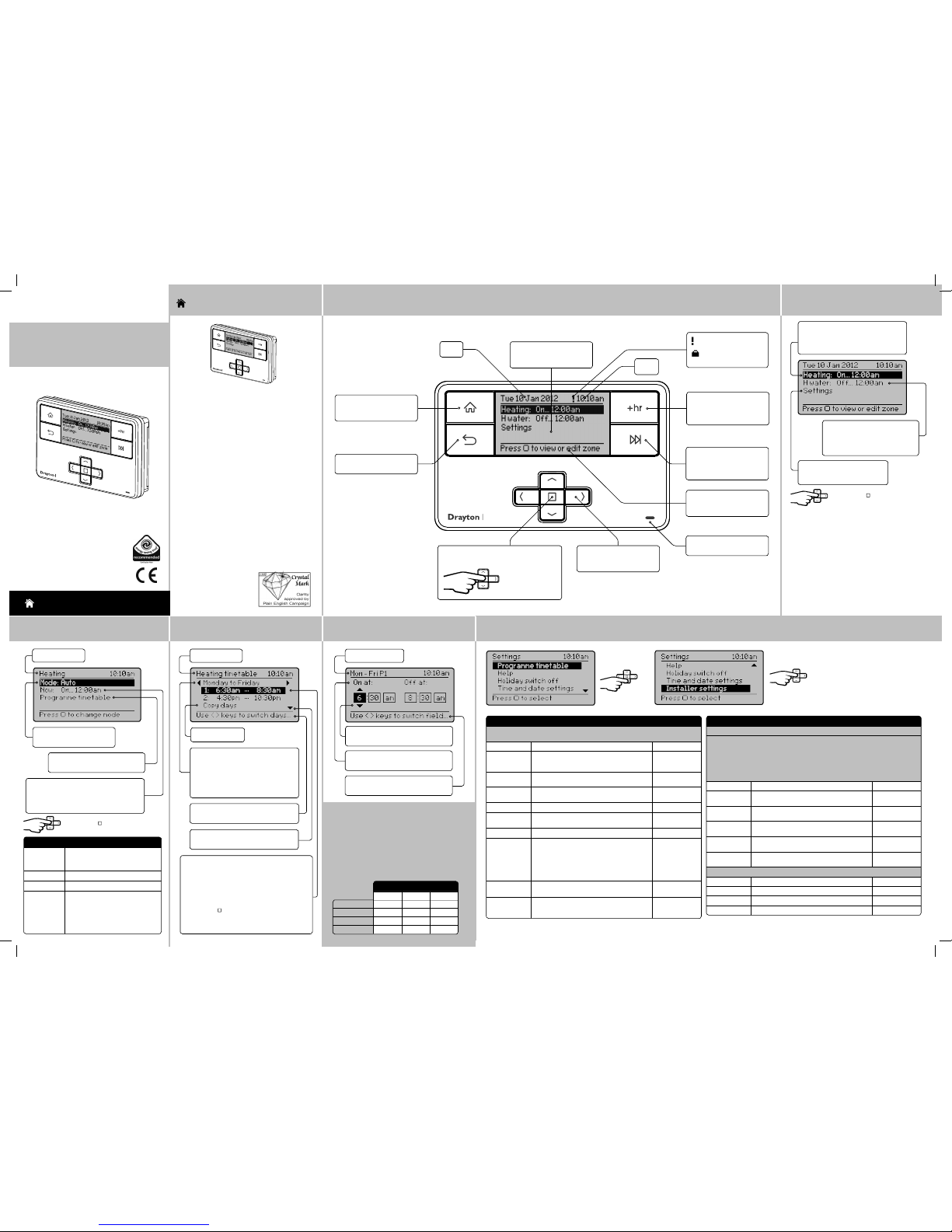
Step 1: Keys and Display
MiTime
Home key: Press to go back
to the home screen at any
time
Date
Home screen showing
current Status and Set tings
link for all zones
Time
Back key: Press to return to
the previous screen
Help text to prompt for
next action. It relates to the
highlighted line
Arrow keys: Press to move
the highlight on screen, and
to change field values
Advance key: Press from the
home or zone details screens
to advance to the next on or
off period
+hr key: Press from the home
or zone details screens to
add up to 3 hours to the
current period
Dual Channel: MiTime T721R
Select key: Press to selec t highlighted
options, and to open and save editor screens
This icon used
throughout these
instructio ns refers
to this button
→
Step 2: Home Screen
→
Zone = Heating
Current status: the pro gramme is On
until 12:00 am
Link to zone detail, see Step 3.
Link to Settings
See further details in Step 6.
Zone = Hot Water
Current status: the pro gramme is
Off until 12:00 am
Link to zone details, see Step 3.
Press Select ( ) to view or edit zone
Step 5: Period Settings
Day range & period
Stored programmes
MiTime contains 3 pre-s et programmes. An example
is shown below. These programmes can be modi fied
according to personal needs and can be s tored by
using a name. Via this name they also can be reloaded.
Once a programme has been modified, the original
factory pre-set will no longer be available. On a
System Reset, only the current loaded programme will
be replaced with the factory setting – see Installation
Guide Step 4.
1st On 6:30am 6:30am 7:00am
1st Off 8:30am 8:30am 9:00am
2nd On 4:30pm 4:30pm 4:00pm
2nd Off 10:30pm 10:30pm 11:00pm
All week Week & Weekend
Mon-Sun Mon-Fri Sat-Sun
Programme 1
Example:
Step 6: Additional User Settings
Press Select to enter a speci fic
Setting. Option s shown below:
→
Feature: Description: Factory Pre-Se t:
Programme
Timetable
On & Off times for the curre nt period can be
modified. See descri ption in ‘Step 4’
Copy days Will copy the curre nt day to one or more other days
Add Period Adds a Time event. It will be added at the cor rect
position within the day. Ther e is a maximum of 4
periods.
Remove Period Removes the selecte d period. There needs to be at
least 1 period
Change
Timetable Type
The visible day-bloc ks available in "programme
timetable" can be define d, see Step 4
Individual days Each day can be programmed individ ually
Week and
weekend
Mon… Fri and Sat… Sun can be programme d as 2
blocks
Default
All week Mon…Sun can be programmed as one block
Stored
programmes
MiTime contains 3 pre -set programmes. The se
programmes can be modi fied according to personal
needs and can be stored by using a nam e. Via this
name they can also be re-loa ded. Once a programme
has been modified, the origi nal factory pre- set will no
longer be available unles s a System Reset is applied see Installatio n Guide Step 4.
Programme 1
Load stored
programme
A pre-set programme c an be loaded
Save current
programme
The current programm e can be saved by name (Each
pre-set program inc ludes: Individual days, wee k/
weekend, all day and custom day sche dules)
Feature: Description: Factory Pre-Se t:
Help Tips Describes the bu tton function s
Holiday switch
off
In the period until holiday s tarts the produc t will operate normally. If holid ay
is disabled manually or term inates automaticall y, the mode before start of
holiday will be re-inst ated.
An enabled holiday will be indic ated with a suitcase sym bol in the top line.
If holiday is active, in the Set: lin e the holiday end date will be indicate d. In
the Summary screen th e suitcase will be visible toge ther with the holiday
temperature.
Status Enable or disable holiday mode . Disabled
Zones Holiday mode can be applied to a spe cific zone or
all zones
All zones
Holiday start
time (From)
Set the time for the star t of your holiday Current time -
nearest hour
Holiday start
date (From)
Set the date for the star t of your holiday Today
Holiday end time
(To)
Set the time for the end of your holiday Current time -
nearest hour
Holiday end date
(To)
Set the date for the end of your holiday Today + 1 week
Time and date settin gs
Set time To set time of day Factory set
Set date To set date Factory set
Daylight saving To enable or disable daylight saving Enabled
Clock format To select 12h or 24h clock mode 12hr
What is a programmer?
... an explanation for householders
Programmers allow you to set ‘On’ and ‘Off ’ time
periods. Some models switc h the central heating and
domestic hot water on and off at the same tim e, while
others allow the domestic hot wate r and heating to
come on and go off at different time s.
Set the ‘On’ and ‘Off’ time per iods to suit your own
lifestyle. On some progr ammers you must also set
whether you want the heating and hot water to run
continuously, run under the chosen ‘On’ and ‘Of f’
heating periods, or be permanen tly off.
The time on the programmer must be corre ct. Some
types have to be adjusted in spring and aut umn at the
changes between Greenwi ch Mean Time and British
Summer Time.
You may be able to temporarily adjust the heating
programme, for example, ‘Override ’, ‘Advance’ or
‘Boost’. These are explained in the manuf acturer’s
instructio ns.
The heating will not work if the room thermos tat has
switched the heating of f. Also, if you have a hot-water
cylinder, the water heating
will not work if the cylinder
thermostat detec ts that the
hot water has reached the
correct temperat ure.
MiTime
HOMEOWNER Guide
Drayton
MiTimeTM Programmer Series
Dual Channel
Model: T721R
Invensys
Customer Service Tel: 0845 130 5522
Customer Service Fax: 0845 130 0622
Technical Helpline: 0845 130 7722
Website: www.draytoncontrols.co.uk
E-mail: customer.care@invensys.com
l
@DraytonControls
x
/DraytonControls
EU Design Regs:- 002180638-1/2/3
User Guide 06490187001 Iss E
MiTime
Step 3: Zone Details
Zone = Heating
Link to Programme timetab le
See further detail in Step 4.
Now: describes the current s tatus, e.g.
programme is On until 12:00 am. Link to
Programme timetable - see fur ther details
in Step 4.
Current mode: Auto
Options: see table below.
Press Select ( ) to change mode
Mode: Description:
Auto The programmer will control the
ON & OFF times in line with the
programmed timetable
Always Off The selected zone will be OFF
Always On The selecte d zone will be ON
All Day
(first on / last
off)
The programme will control the
ON & OFF times in line with the
programmed timetable, bu t using
only the first ON event and the last
OFF event - it will remain ON in
between these two per iods.
Step 4: Prog. Timetable
→→
→
Zone = Heating
Help text: Use left /right buttons to
select the days you want to change
Period 1 settings: describes the current timetable
settings, e.g. Heating has been programmed to
turn On at 6:30am and go off at 8:30am
Period 2 settings: describes the current timetable
settings, e.g. Heating has been programmed to
turn On at 4:30pm and go off at 10:30pm
Press select (
) when highlighted to adjust
settings (see Step 5)
Up to 4 periods can be programmed
Arrow denotes that furt her options are
available if you scroll down.
Timetable day range: Monday to
Friday (Week and weekend)
Options: Individual days (7day), Week and
weekend (5/2day), All week (24hr). The
available blocks depend on the selection
in menu “change timetable type”
Link to Copy days
HOMEOWNER Guide
LED: Illuminates when any
zone is scheduled to be ON
Help text: Use left /right buttons to
change fields
Period settings: On at 6:30am and Of f
at 8:30am
Highlight shows adjust able field:
Use up/down buttons to adjust values
: Indicates a Service warning
: Indicates that holiday
is enabled
6444 Invensys MiSeries 2 Channel 06490187001 IssE.indd 1 27/09/2013 09:09
Technical Data
MiTime T721R
Voltage 230V a.c. +10% -10% 50Hz
Switch Rating 2 (1) A 230V a.c. each switch
Ambient temp Op erating: 0º to 45ºC
Storage: -20ºC to 50ºC
Without mains
power
Display: blank
Time: always kept
Programme times: always preserved
Programming
resolution
1 minute
Wiring Fixed wiring only, to comply with
current IEE regulatio ns
Maintenance Must be maintained by a quali fied
electrician or hea ting engineer
Pollution degree 2
Rated impulse
voltage
2.5kV
Ball pressure tes t
temperature
75ºC
Relevant EC
Directives:
2006/95/EC Low Voltage Direc tive
2004/108/EC Electro magnetic
Compatibilit y Directive
2006/66/EC Batter y Directive
2011/65/EU RoHS Directive
Applied Standar ds: EN60730 -1; EN60730-2-7
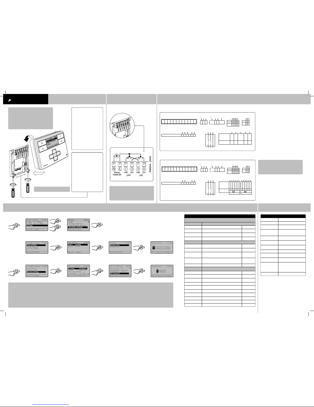
Step 2: Wiring
→
Connect the wiring as shown belo w.
Step 3: Connection Charts
Step 4: Installer Settings
Arrowed numbers relat e to the junction box.
* Consult boiler handbook for de tails of pump
overrun wiring.
Make the wiring connections , as shown, for the
appropriate system. For sur face wiring, snap out the
cable entry str ip on the bottom edge of the wall-plate.
MiTime units are double- insulated and need no earth
connection, but an ear thing continuity (loop) terminal is
provided for convenience.
After wiring, plug in the unit and tighten th e securing
screws. Check the mains input has a 3A fuse, and switch
on the mains.
Biflo system: Model T721R
LWC3 Junction Box
Pump Room Thermostat Cyl. ThermostatBoiler
L N E
7 2 3
Perm.
L
N E
Switch
L
71
2 3
3 2 1 4 5
COM
CALL
SAT.
RTS 1&2
RTS 4,6,9&10
Function
N L 3
N L
E N L
1 3
68
COM
CALL
SAT.
Drayton
HTS 3
Function
C 1 2
1L2N3E4 5 6 7 8 9 10 11 12
LWC3 Junction Box
Pump Room Thermostat Cyl. ThermostatBoiler
Mains Input - 230V a.c. Motorised Valve
3A
MiTime Programmer
CHONHWONCH
OFFHWOFF
LN 4321
2 1
NOT
USED
8 4
L N E
7 2 3
Perm.
L
N E
Switch
L
71
2 3
DHW VALVE CH VALVE
Function of
Leads
Drayton
22mm 2 Port Valve
28mm 2 Port Valve
Aux.SWMotor
NL
Brown
Blue
Yell/Green
Orange
Grey
White
(28mm only)
N.CN.O
CE
6 32 7 1 9
5 32 7 1 10
Aux.SWMotor
NL
Brown
N.CN.O
CE
Blue
Yell/Green
Orange
Grey
White
(28mm only)
The white wire (28mm Valves) becomes live when the valve closes, it is not
used and is wired to 'spare' terminals for safe isolation.
1 32
L N E
Mains
Isolator
3 2 1 4 5
COM
CALL
SAT.
RTS 1&2
RTS 4,6,9&10
Function
N L 3
N L
E N L
1 3
68
COM
CALL
SAT.
Drayton
HTS 3
Function
C 1 2
1L2N3E4 5 6 7 8 9 10 11 12
Twinzone system: Model T721R
→
INSTALLATION Guide Step 1: Mounting the Wall-plate
! IMPORTANT:
Installation mus t only be carried out by a
qualified electr ician or heating engineer.
Make sure mains input has a 3 amp fuse.
! CAUTION! Before inst allation, make sure the
mains supply is switche d off!
MiTime
Option 2: Using an existing
wall-plate
Loosen the securing screws
on the old programmer and
unplug it. Check that there is
70mm clearance to the right of
the wall-plate and 25mm above
it. Check the wiring diagram for
your product model to compare
terminals and, if necessar y,
change the wiring of the wallplate to suit. Now plug the MiTime
unit into the wall-plate and tighten
the securing screws.
Check the 3A fuse, and switch on
the mains.
Option 1: Fitting a new wall-plate
The ideal location is 1.2m above
floor level, with reasonable
lighting, good access, no
condensation, no extrem es of
temperature and a support ing
surface that fully cover s the
back of the unit. Position with
70mm clearance to the right,
25mm above and sufficient room
to access the securing screws
underneath. Fix, with ter minals
at the top, either direct to a flat
wall using wall plugs and No. 6 x
1” (25mm) woodscrews, or on a
flush mounting single conduit box
type UA1 (BS4662) using M3.5 x
14 bolts.
! DO NOT use a surface mounting box
→
Feature: Des cription: Factory Pre-Set:
Installer Set tings
! CAUTION! These settings should only be modified by a qualified
person. They can influence safety and the proper functioning of the system.
Zone Settings Customise the MiTime accordin g to personal requirement s
Select zone Select a zone for the fol lowing actions
Rename zone To rename an exis ting zone Heating,
H Water
Delete zone To delete an existing zone. The las t zone cannot be
deleted
Min. 1 Zone
Add Zone Add a new zone, apply a name & bind a ther mostat.
A time table can be applied.
Max. 2 Zones
System Setting s Th ese are the settings whic h will be applied to the MiTime unit
View product
information
View the product det ails, e.g. Part number, Firmware
revision etc.
Backlight sett ings Available options are: On with timeout, Al ways On,
Always Off
On with
timeout
Screen lock Enable or disable the lock in the Mi Time unit
To Lock: Enter a 3 digit code for protectio n
To Unlock: Enter the 3 digit code
000
Master Code 401
Powersave To reduce power use when not being adjust ed.
Available options are: Powers ave off, partial display
with key data, no display until bu tton press
Powersave off
System Reset Will reset all settin gs to factory pre- sets
Service Setti ngs To help comply wi th regulation 36 of the Gas safet y [Installation & Use]
regulations 1998
Si Status Enable or disable Ser vice mode Disabled
Si Type Select betwe en, Reduced Comfort, Sw itched Off &
No Effect (warnin gs only)
Reduced
Comfort
Reduced comfort
duration
Set the duration for the reduc ed comfort sett ing (0
to 60mins.)
15 min.
Si due date Set the date th e next boiler service is due Today
Warning start Set the numb er of days for the on-screen ser vice due
warning (0 to 60 days)
30 days
Boost status Enable or dis able Service Boos t Disabled
No. of boosts Set the nu mber of Boosts to be available af ter service
is due (1 to 99)
10
Audible Alarm Enabl e or disable Service Alar m Enabled
Installer tel Enter the Installer teleph one number if required
Set password Set pas sword to restrict ac cess to the Service set tings 0 000
From the Home screen, select Set tings, then Installer set tings as shown.
From here you can edit the assigned zones, rename the m if required and adjust the Service set tings.
If using the Service feature, remem ber to set the Password when complete.
! IMPORTANT:
Always switch off th e mains before removing
the MiTime programm er – and never fit it to a live
wall-plate!
→
LWC3 Junction Box
Pump Room Thermostat Cyl. ThermostatBoiler
L N E
7 2 3
Perm.
L
N E
Switch
L
71
2 3
3 2 1 4 5
COM
CALL
SAT.
RTS 1&2
RTS 4,6,9&10
Function
N L 3
N L
E N L
1 3
7 86
COM
CALL
SAT.
Drayton
HTS 3
Function
C 1 2
1L2N3E4 5 6 7 8 9 10 11 12
LWC3 Junction Box
Pump Room Thermostat Cyl. ThermostatBoiler
Mains Input - 230V a.c. Motorised Valve
3A
L N E
7 2 3
Perm.
L
N E
Switch
L
71
2 3
1 32
L N E
Mains
Isolator
3 2 1 4 5
COM
CALL
SAT.
RTS 1&2
RTS 4,6,9&10
Function
N L 3
N L
E N L
1 3
7 86
COM
CALL
SAT.
Drayton
HTS 3
Function
C 1 2
1L2N3E4 5 6 7 8 9 10 11 12
MiTime Programmer
CHONHWONCH
OFFHWOFF
LN 4321
2 1 8
NOT
USED
6 4
Function
Drayton
22mm 3 Port Mid Position Valve
28mm 3 Port Mid Position Valve
White
Grey
Orange
Blue
Yellow/Green
CH
On
HW
Off
Boiler
Live &
HW On
N E
25 38 7
! IMPORTANT:
Always switch off th e mains before removing
the MiTime programm er – and never fit it to a live
wall-plate!
Internal Wiring
→
→
→
→
→ →
→
→
→
→
✎ Installer Notes:
6444 Invensys MiSeries 2 Channel 06490187001 IssE.indd 2 27/09/2013 09:09
 Loading...