

Drayton SHR 521 20 Installation & Operation Manual
Thank you for buying a Drayton product.
Please read this manual carefully to get the best perfomance from this unit.
Drayton SHR 521 20
Installation
Commissioning
Operation
Fault finding
Examples
SHR 521 20
manual
B
49000720
*49000720*

SHR 521 20
© Drayton 06334 SHR 521 20.monen.indd
| 2
Contents
Disclaimer ............................................................................2
Safety Regulations ...............................................................2
Technical data and function ...............................................3
1. Installation .............................................................5
1.1 Mounting .................................................................................. 5
1.2 Electrical wiring ...................................................................... 5
1.2.1 Standard solar system ........................................................... 6
1.2.2 Solar system and back-up heating ...................................... 6
2. Operation and function ........................................7
2.1 Adjustment buttons .............................................................. 7
2.2 System-screen display ........................................................... 7
2.2.1 Channel indication ................................................................. 7
2.2.2 Tool bar .................................................................................... 7
2.2.3 System screen ......................................................................... 8
2.3 Flashing symbols ..................................................................... 8
2.3.1 System-Screen flashing symbols ......................................... 8
2.3.2 Flashing symbols ..................................................................... 8
3. Commissioning ......................................................9
4. Control parameter and indication channels ... 10
4.1 Channel overview ................................................................ 10
4.1.1-6 Indication channels ..............................................................11
4.1.7-17 Adjustment channels ...........................................................12
5. Tips for fault finding ........................................... 17
5.1 Miscellaneous ........................................................................18
6. Accessories ......................................................... 20
Security advice
Please pay attention to the following security advice in order
to avoid danger and damage to people and property.
Instructions
Attention should be paid
- to the statutory provisions for prevention of industrial
accidents,
- to the statutory provisions for environmental protection,
- to the Health and Safety at Work Act 1974
- to Part P of the Building Regulations 2005
- to BS7671 Requirements for electrical installations and
relevant safety regulations of DIN, EN, DVGW, TRGI, TRF
and VDE.
This instruction is exclusively addressed to authorised
skilled personnel.
- Only qualified electricians should carry out electrical
works.
- Initial installation should be effected by named qualified
personnel
Declaration of conformity
We, Invensys Controls Europe, declare under our sole responsibility that our product SHR 52120 complies with the
following standards:
EN 55 014-1
EN 60 730-1
According to the regulations of the above directives, the
product is labelled with :
89/336/EWG
73/ 23/EWG
SHR 521 20
© Drayton 06334 SHR 521 20.monen.indd
3 |
!
• Backlit multifunction display
to monitor solar thermal systems
• Up to 4 Pt1000 temperature
sensors
• Heat balancing
• Stylish, easy-to-install housing
• Simple 3-button operation
• Solar operating hours counter
and thermostat function
Technical data
Housing:
plastic, PC-ABS and PMMA
Protection type: IP 20 / DIN 40050
Ambient temp.: 0 ... 40 °C
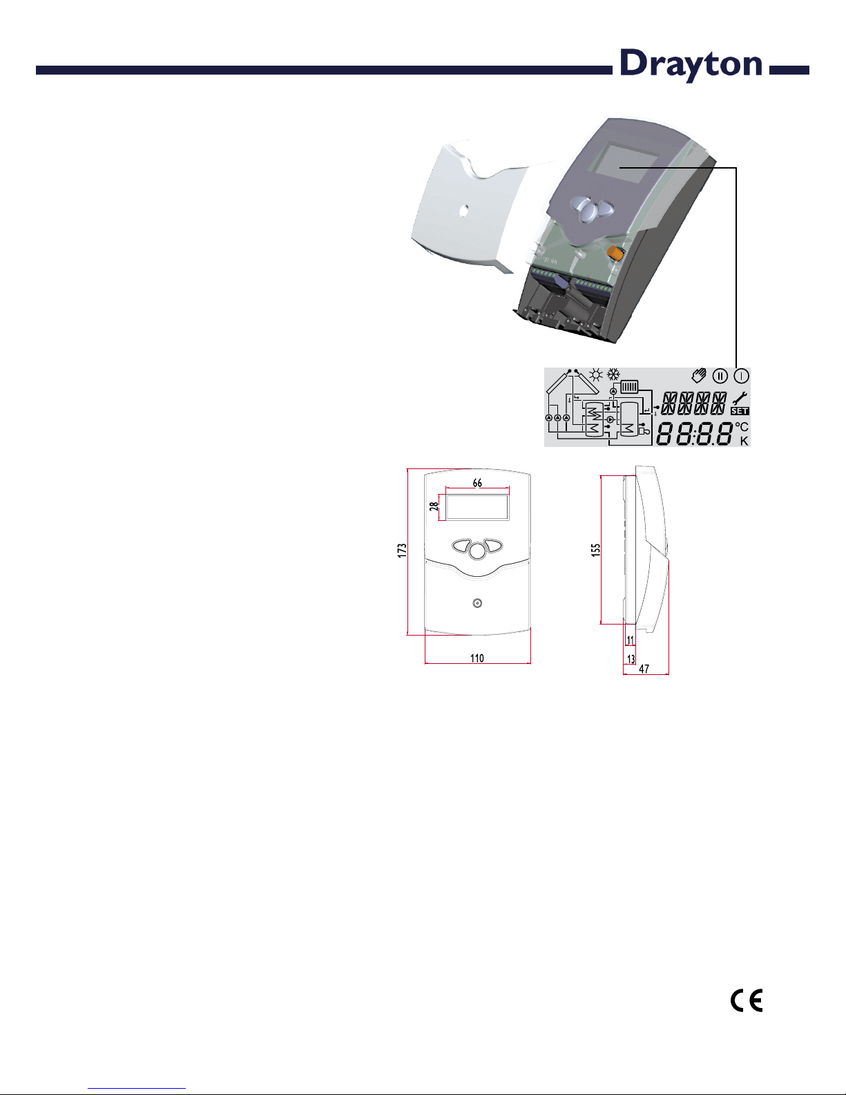
Size: 172 x 110 x 46 mm
Moun tin g: wall mounting, panels
mounting is possible
Di s play: S ystem s creen for sys tem visualisation, 16-segment display,
7-segment display, 8 symbols for system
status and operating control lamp
Operation: by 3 pushbuttons on the
front of the housing
Functions: Temperature differential
controller with optional system functions. System monitoring according
to BAW-guidelines, operating hours
counter for solar pump, tube collector
special function, as well as heat quantity balancing.
Inputs: for 4 Pt1000 temperature
sensors
Outputs: depending on version, see
section „controller versions“
Power supply:
220 ... 240 V~
Switching Capacity:
4 (2) A 220 ... 240 V~
Mode of operation:
Typ 1.b
Breaking capacity per relay:
electromechanical relay:
4 (2) A 220 ... 240 V~
Parts included:
1 x SHR 521 20
1 x accessory bag
1 x spare fuse T4A
2 x screws and wall plugs
4 x cable clamps and screws
Additionally enclosed in the full kit:
1 x sensor FKP6
1 x sensor FRP6
SHR 521 20
© Drayton 06334 SHR 521 20.monen.indd
| 4
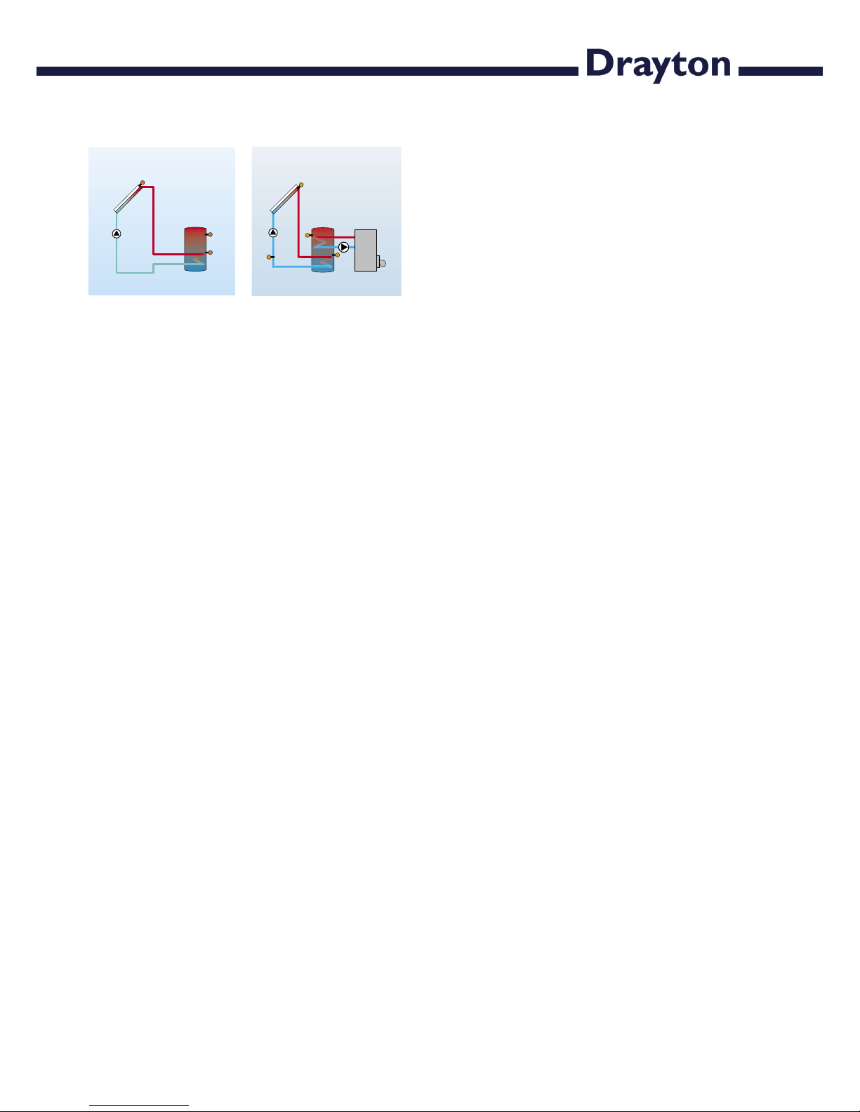
Examples SHR 521 20
Please find detailed connection diagramms for
these systems in chapter 1.
Standard solar systems
Solar systems with
dual-mode DHW cylinder
SHR 521 20
© Drayton 06334 SHR 521 20.monen.indd
5 |
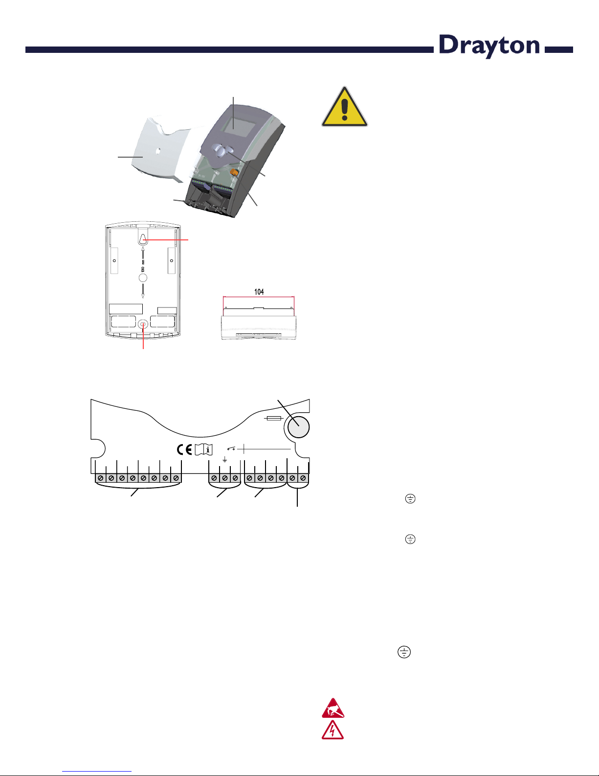
display
pushbuttons
can fuse 4A
cable conduits in the clamps
cover
1.1 Mounting
The unit must only be located indoors. It is not suitable
for installation in hazardous locations and should not be
sited near to any electromagnetic field. The controller must
additionally be equipped with an all-polar gap of at least 3 mm
or with a gap according to the relevant installaton regulations,
e.g. LS-switches or fuses. Please ensure that sensor cables
and AC power cables are kept well apart.
1. Unscrew the cross-head screw of the cover and remove
it from the housing.
2. Mark the upper fastening point on the wall and insert the
enclosed wall plug and screw.
3. Hang the housing at the upper fastening point and mark
the lower fastening point on the wall (hole pitch 130 mm),
afterwards put the lower wall plug.
4. Fix the housing on the wall.
1. Installation
Warning!
Switch-off mains supply before
opening the housing.
1.2 Electrical wiring
The power supply to the controller must only be made by
an external mains switch (last step of installation!) and the
mains voltage must be 220 ... 240 Volt (50...60 Hz). Flexible
lines are to be fixed at the housing by enclosed cable clamps
and screws.
The controller is equipped with 2 relays to which the out-
puts e.g. pumps, valves etc. can be connected:
• Relay 1
18 = line R1
17 = neutral N
13 = earth terminal
• Relay 2
16 = line R2
15 = neutral N
14 = earth terminal
The temperature sensors (S1 up to S4) will be connected
to the following terminals regardless of polarity:
1 / 2 = Sensor 1 (e.g. Sensor collector 1)
3 / 4 = Sensor 2 (e.g. Sensor store 1)
5 / 6 = Sensor 3 (e.g. Sensor TSPO)
7 / 8 = Sensor 4 (e.g. Sensor TRL)
The power supply is connected to the terminals:
19 = neutral N
20 = Line L
12 = earth terminal
hanging
fixation
Electrostatic discharge can damage electronic components!
Dangerous voltage on contact!
1 2
S1 S2 S3
3 4 5 6
Temp. Sensor
Pt1000
LNR1NR2N
201918171615
S4
7 8
141312
2 (1) A (220 ...240)
V~
2 (1) A (220 ...240)
V~
R1
R2
T4A
220 ... 240
V~
mains terminals
fuse
output terminals
Sensor terminals
earth terminals
SHR 521 20
© Drayton 06334 SHR 521 20.monen.indd
| 6
S1
S2
S4 / TRF
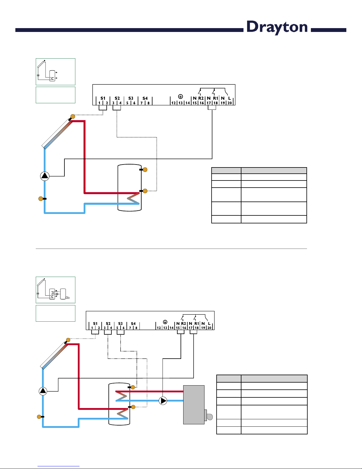
1.2.1 Allocation of terminals for system 1 Standard solar system with 1 store, 1 pump and 3 sensors. The sensor S4 / TRF can optionally be used for heat
quantity balancing.
R1
Arr 1
S3
R2
S1
S2
R1
S3
S4 / TRF
Solar system and dual-mode DHW cylinder with 1
store, 3 sensors and backup-heating. The sensor S4 / TRF can
optionally be used for heat quantity balancing.
Arr 2
1.2.2 Allocation of terminals for system 2
Symbol Specification
S1 collector sensor
S2 store sensor lower
S3 store sensor upper
S4 / TRF sensor for heat quantity
balancing (optional)
R1 solar pump
R2 pump for heat exchange
Symbol Specification
S1 Collector sensor
S2 Store sensor lower
S3 Store sensor upper
(optional)
S4 / TRF Sensor for heat quantity
measurement (optional)
R1 Solar pump
 Loading...