

Drayton P710R Installation Manual
MiStat Programmable
Room Thermostat
Model: P710R
Custo mer Servic e Tel: 0845 130 5522
Custo mer Servic e Fax: 0845 130 0622
Technical Helpline: 0845 130 7722
Website: www.dray toncontrols.co.uk
E-mail: customer.care@invensys.com
l
@DraytonControls
x
/DraytonControls
EU Design Re gs:- 002180638-1/2/3
Installation Guide 06490189001 Iss E
MiStat
INSTALLATION Guide
Applications
The electronic room thermostat MiStat P can be used
for temperature control together with:
• Boilers
• Oil and gas w arm water heati ng
• Actua tors of fl oor heating s ystems or radi ators
• Circulating pumps
• Heat pumps
A MiStat R re ceiver is requir ed for operatio n.
Note: To ensure a properly working heating
syste m, the menu items i n the Installe r settings
have to be se t according to the n eeds of the
heating s ystem, see s tep 5.
Caution!
The radi o receiver may be in stalled onl y by a competent
elect rician in compl iance with the ci rcuit diagram
enclos ed in the top housin g cover or in complia nce
with the se instruc tions. The cu rrent safet y regulations
must be o bserved.
In order to a chieve protec tion class II, a dequate
installation measures must be taken.
This rad io receiver, which ca n be installe d separately,
is design ed exclusively f or temperatur e control in dry
and clos ed rooms and sta ndard environme nts. This
elect ronic device wa s created accord ing EN60730-1, it
operates according working principle 1C.
Step 1: Mounting the Wall-plate
! IMPORTANT:
Inst allation mus t only be carrie d out by a
qualifi ed electrician or heating engineer.
Make sure m ains input has a 3 a mp fuse.
! CAUTION! Before installation, make sure the
mains su pply is switc hed off!
Option 2: Using an existing wall-plate
Loosen t he securing sc rews on the old rece iver
and unplu g it. Check that t here’s 20mm
clearan ce to the right of th e wall-plate an d 25mm
above it . Check the wirin g diagram for your
produc t model to compar e terminals and, i f
necess ary, change the w iring of the wall -plate to
suit. No w plug the MiStat R u nit into the
wall-p late and tighten t he securing sc rews.
Check th e 3A fuse, and swit ch on the mains.
Option 1: Fitting a new wall-plate
The ideal l ocation is clo se to the boiler or c entral
heating s ystem. For th e best perfo rmance inst all
in an open sp ace, at least 30 cm distance f rom any
metal ob jects incl uding wall boxes an d the boiler
housing . It is recommend ed that the MiSta t R is
mounted o n the wall neares t the fi nal loc ation of
the MiSta t P room unit and not l ess than 30cm
from the b oiler side panel .
Loosen t he securing sc rews, remove the wa llplate
and, if sur face wiring i s to be used, snap ou t
the cabl e entry str ip on the botto m edge of the
wallpla te with a pair of plie rs. Fix the wallp late,
termina ls at the top, eithe r direct onto th e fl at
wall usin g wall plugs and no 6 x1” wood s crews
or on a plas tic fl ush mou nting single con duit box
using M3.5 x 14 sc rews. Check tha t there’s 20mm
clearan ce to the right of th e wall-plate an d 25mm
above it . Complete the wir ing to the MiStat R
wallpla te in accordance wi th the wiring dia gram
in step 2, to c omply with cur rent IEE regulat ions.
Place the M iStat R onto the wa llplate and tight en
the securing screws.
Check th e 3A fuse, and swit ch on the mains.
Warning: Installi ng the MiStat R too c lose to the
metal si de panel or mains c ables may inter fere
with the r adio signal.
! DO NOT
use a sur face
mounting box
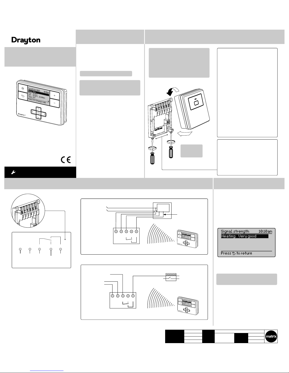
Step 2: Wiring
This product is double insulated and does not
require an e arth connec tion. The MiSt at R should
be wired to t he boiler or cent ral heating wir ing
using the c orrect ty pe of cable or fl ex. The MiStat
R should be w ired to replace ha rd wired room
or progra mmable thermo stats, as s hown on the
system or boiler wiring diagrams.
Always check other manufacturers instructions for
compatibility.
N L 1 2 3
230V AC 50Hz
Fused 3A
Common
heating
satisfied
or call for
cooling
Call for
heat
Volt free contacts
Combi boiler basic wiring layout
Zone control basic wiring layout
MiStat R
N L 1 2 3
L N -
Radio signals
to MiStat R - no wiring
Sw
i
tched
230V AC
fused 3A,
Internal
boiler
electronics
External
controls
connections
N L 1 2 3
L
MiStat R
MiStat R
Switched live
from wiring
centre
Motorised valve
N
To boiler
and/or
pump
Radio signals
to MiStat R - no wiring
230V AC
fused 3A
N L 1 2 3
L -
N -
Radio signals
to MiStat R - no wiring
Sw
i
tched
230V AC
fused 3A,
Internal
boiler
electronics
External
controls
connections
Step 3: Signal Strength
The MiSt at Programmabl e Room thermos tat is prebound to th e MiStat receiv er in the facto ry so they jus t
need to be p ositioned in th e best place for w ireless
communication.
To help with thi s there is a built in Si gnal strengt h
indica tor as shown below (s ee also Step 5 Inst aller
settings).
It is reco mmended that th e signal streng th is ‘Good’
or ‘Very Good’ to ensure ongoing communication
is maintained.
If ‘Poor’ is displayed, look for a better location.
If ‘No Sig nal’ is displayed , try connec ting again wit h
the room un it in a differe nt position.
Note: If not bound, t he bind screen wil l be visible.
For commissioning see Step 6
Client Invensys File Name 7378 Drayton Instruction Manual Update 06490189001
Artworker -
Proof Stage
PRINT
Finished Size 280x 297mm
Creative Director Mike Lane Artwork % 100%
Modification Date 20/04/15 11:59AM Bleed 3mm
MiStat
MiStat
Technical Data
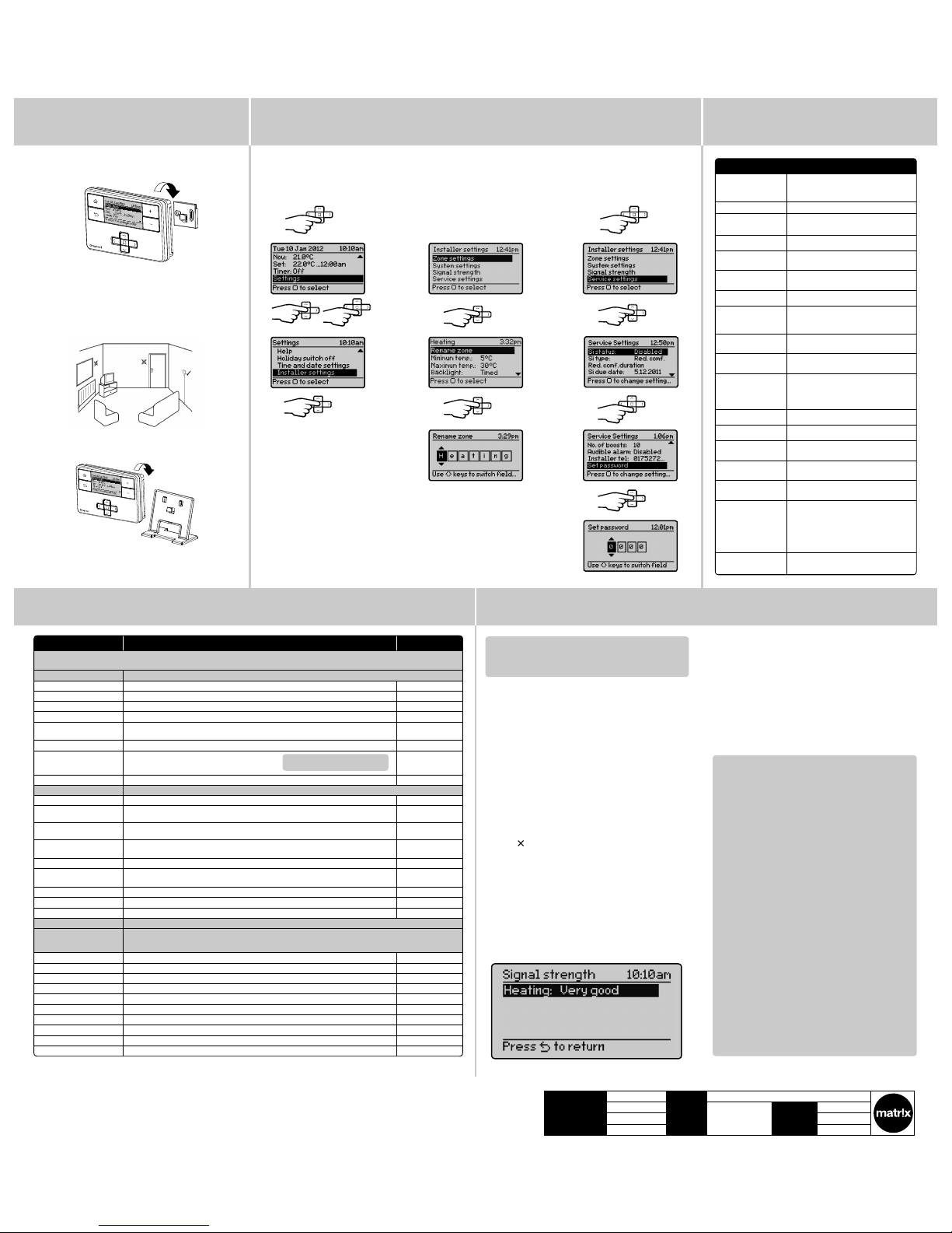
Step 5: Installer Settings
Step 5: Installer Settings (continued)
Feature: Description: Factory Pre-Set:
Installer settings
! CAUTION! These set tings shoul d only be set- up by a qualifi ed person. Th ey can infl uenc e safety an d the
proper functioning of the system.
Zone settings Customise the MiStat according to personal requirements
Rename zone To rename an exi sting zone Heating
Minimum temp It will no t be possible t o set a lower tem perature 5°C
Maximum temp It will no t be possible t o set a higher te mperature 30°C
Backlight Av ailable opti ons are: On wit h timeout, A lways Off On with t imeout
Powersave To reduce pow er use when not b eing adjust ed. Availabl e options are: Pa rtial
display w ith key data, n o display unti l button pr ess.
Partial display
Temp. offset Adjust t he displaye d temperatu re to persona l needs 0.0°C
Screen lock Enable or d isable the lo ck in the room un it.
To Lock: Ente r a 3 digit code fo r protecti on
To Unlock: En ter the 3 digit c ode
Disabled
Maste r Code 401
RF binding Bind the remo te thermos tat to the rec eiver. Pre-bound
System settings Customise the MiStat according to system requirements
Contro l type Selec t TPI, TP or On /Off TPI
Cycle rat e (only when
Contro l type is TPI or T P)
Selec t 6 (Gas) cph (cycle s per hour), 12 (Elec tric) cph or 3 (Oil) c ph 6 cph
Min on/of f (only when
Contro l type is On/of f)
Selec t 1 to 30 minutes ( The minimum d uration for t he relay to be On or O ff) 5 min.
Hysteresis (only when
Contro l type is On/of f)
Selec t Off, 0.1 to 5° (Off = N o temperat ure hystere sis, even on ver y low temp.
change s, the relay wil l switch over a ccording to Mi n On/Off ti me)
0.5°C
Frost protection Enable or d isable the Fro st protec tion in the MiS tat unit. (Temp erature = 5°C) Disabled
Valve protection The ou tput will be ac tivated f or the speci fi ed tim e (in minutes). Th is will happen
weekly, re lated to the la st actua tion of the out put. Selec t 0 to 10 minutes .
0 minute s (Off)
Optimum/Delayed start Available options are: Off, Optimum, Delayed Off
System r eset Will reset a ll setting s to factor y pre-se ts
View product information Vie w the produc t details, e. g. Part numbe r, Firmware revi sion etc.
Signal strength Info rms about th e current sig nal streng th, see step 3 .
Service settings To help comply w ith regulat ion 36 of the Gas s afety [Ins tallati on & Use] regulat ions 1998. On expi ry of
the warn ing period, t he alarm soun ds, star ting at midd ay and contin uing until a bu tton is pre ssed. This is
repeat ed daily until t he servi ce functi on is reset. To ent er these set tings a cod e is request ed.
Si stat us Enable or disable Service mode Disabled
Si type Selec t between , Reduced comf ort, Swit ched off & No e ffect (war nings only) Reduced Comfor t
Reduced comfort duration S et the durat ion for the redu ced comfor t settin g (0 to 60mins.) 15 min.
Si due date S et the date th e next boiler s ervice is d ue Toda y
Warning s tart Se t the number of da ys for the on- screen ser vice due warn ing (0 to 60 days) 30 days
Boost status Enable or disable Service Boost Disabled
No. of boos ts Se t the number of B oosts to be a vailable af ter serv ice is due (1 to 99) 10
Audible alarm Enable or disable Service Alarm Enabled
Installer tel. Enter the Installer telephone number if required
Set password Set pa ssword to res trict ac cess to the Se rvice set tings 0000
Step 6: Commissioning
Note: Only needed i f not already bou nd, ie if
replacing either the MiStat thermostat or the
MiStat receiver.
1. Turn on pow er for the receive r. The red LE D will
come on.
If LED is gr een or Off, th e device is alrea dy
bound, no further action needed here (If a
separate programmer/Timer is fi tted, ensure
that it is s witched on)
2. Push the bu tton for >5 Secon ds and the LED
will fl ash red – yellow – gree n --- -red – yell ow green…
3. Enter binding mode on the corresponding
MiStat ro om unit, see Step 5: In staller set tings
Important: It is es sential, that t he binding is
carried out between the corresponding room
unit and t he receiver
4. The poss ible results a re as follows;
1.‘
Bind OK’ wi ll be indicated o n the MiStat
room unit i f binding was succ essful.
After a f ew seconds the Si gnal strengt h will be
indica ted on both the MiSt at room unit and t he
MiStat re ceiver, see below.
2. ‘ Bind Failed ’ will be displaye d if
unsuccessful.
3. If ‘Poor’ s ignal is displaye d, look for a bet ter
location.
4. If ‘No Sign al’ is displayed, t ry connec ting
again wit h the room unit in a di fferent pos ition.
MiStat Ro om Unit
MiStat Receiver
Immediately after binding, these signals will indicate
the signal quality for 1 minute.
• t hree green fl a shes = Very good si gnal
• do uble amber fl a shes = Good sign al
• si ngle red fl as hes = Poor signal
• s teady red = No sign al
To check the wireless connection
A green LED o n the receiver wil l indicate a good R F
connection.
From the Ho me screen, selec t
Settings, then Inst aller settings
as shown.
From here you c an edit the
assign ed zones, rename t hem if
require d and adjust the Se rvice
settings.
If using t he Service fea ture,
remembe r to set the Password
when complete.
Step 4: Mounting Options
Once the b est positi on has been iden tifi ed , the MiStat
should be fi xed to the wall usin g the wall bracket a s
shown.
Care sho uld be taken to moun t the thermos tat in a
positi on which is not sub ject to direc t sunlight or
draughts. Preferably it should be mounted on an inside
wall abou t 1.2m (4ft) above the fl oor in a po sition where
it can re spond to room temp erature but aw ay from the
direc t infl uence o f radiators or ot her appliance s giving
off hea t.
NB. MiSta t can also be pos itioned usin g the table
stand included.
MiStat
It has to be p laced in a locati on where it will be a ble to
control the room temperature.
Installer Notes:
Customise the controller according to application
requirements (from installer only)
MiStat P 721R & MiStat R111M
Supply voltage MiStat P: 2 x A A 1,5V alkalin e
batteries
MiStat R : 230V
Switch rating MiStat R: 2(1)A 230V a .c.
Ambient
temperature
Operat ing: 0°C to 45°C;
Storag e: –20°C to 55°C;
Battery life MiStat P: 2 year s (typicall y)
Temperature
range
5°C to 30°C
Temperature
resolution
0.5 °C, di splay and set ting
Control accuracy <0.6°C a t 4°/hour
Wiring MiStat R : Fixed wirin g only, to comply
with cur rent IEE regu lations (BS7671)
MiStat P: N o wiring requ ired
Mounting MiStat R : Industr y standard w allplate
MiStat P: Wa ll bracket or t able stand
Radio frequency 868.3MHz (Bi-directional
communication)
Radio signal range 30m ty pically. The r ange may be
affected by the composition / density
and numbe r of walls bet ween the
MiStat P a nd MiStat R
Pollution degree 2
Software class A
Rated impulse
voltage
MiStat R : 2.5kV
Ball pressure test
temperature
MiStat R : 75°C
Energy Class IV = 2% ( According to EU 811/2013,
812/ 2013, 8 13/2013 , 814/ 2013)
Relevant EC
Directives:
2006/95/ EC Low Voltage D irective
2004/108/EC Electromagnetic
Compatibility Direct ive
1995/5/EC R&TTE Directive
2006/66/EC Battery Directive
2011/65/EU RoHS Direc tive
Applied
Standards:
EN60730 -1; EN60730-2-7; EN6 0730-2-9
ETSI EN 30 0 220-3; ET SI EN 301 489-3
User Code:
1.2m
Client Invensys File Name 7378 Drayton Instruction Manual Update 06490189001
Artworker -
Proof Stage
PRINT
Finished Size 280x 297mm
Creative Director Mike Lane Artwork % 100%
Modification Date 20/04/15 11:59AM Bleed 3mm
 Loading...