

Drayton MiTime T720R, MiTime T710R, MiTime T740M, MiTime T740R, MiTime T720M Installation Manual
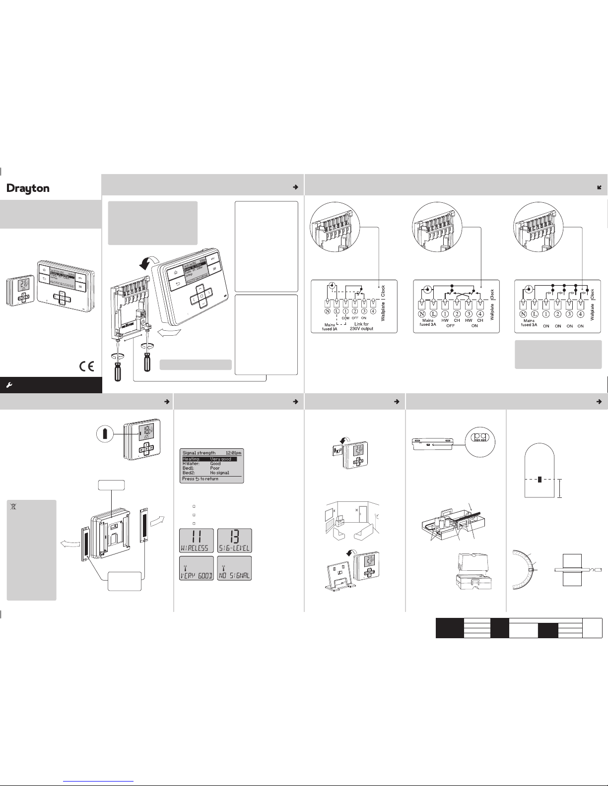
Step 1: Mounting the Wall-plate
! IMPORTANT:
Installation mus t only be carried out by a
qualifi ed electrician or hea ting engineer.
Make sure mains input has a 3 amp fuse.
! CAUTION! Before installati on, make sure the
mains supply is switched of f!
Option 1: Fitting a new wall-plate
The ideal location is 1.2m above
fl oor level, with reasonable
lighting, good access, no
condensation, no extreme s of
temperature and a suppor ting
surface that fully cover s the
back of the unit. Position with
70mm clearance to the right,
2
5mm above and suffi cient room
to access the securing screws
underneath. Fix, with term inals
at the top, either direct to a fl at
wall using wall plugs and No. 6 x
1” (25mm) woodscrews, or on a
fl ush mounting single conduit box
type UA1 (BS4662) using M3.5 x
14 bolts. Check the 3A fuse, and
switch on the mains.
! DO NOT use a surface mounting box
Battery
Handling
Batteries, recharg eable or
not, should not be disp osed
of into ordinary household
waste. Instea d, they must be
recycled properly to prote ct
the environment and cut
down the waste of precious
resources.
Your local waste
management authorit y can
supply details concer ning the
proper disposal of bat teries.
In compliance with the EU
Directive 2006/66/EC, th e
button cell batt ery located
on the printed circui t board
inside the product , can be
removed at the end of the
product life, by profes sional
personnel only.
Option 2: Using an existing
industry st andard wall-plate
Loosen the securing screws
on the old programmer and
unplug it. Check that there is
70mm clearance to the right of
the wall-plate and 25mm above
it. Check the wiring diagram for
your product model to compare
terminals and, if necessar y,
change the wiring of the wallplate to suit. Now plug the MiTime
unit into the wall-plate and tighten
the securing screws.
Check the 3A fuse, and switch on
the mains
.
MiTime Programmer Series
RF Packs
Technical Helpline: 0333 7000 622
Website: www.draytoncontrols.co.uk
E-mail: customer.care@draytoncontrols.co.uk
l
@DraytonControls
x
/DraytonControls
EU Design Regs:- 002180638-1/2/3
Installer Guide 06490194001
Iss K
INSTALLATION Guide
Single Channel: MiTime T710R
Dual Channel: MiTime T720R, T720M
Multi Channel: MiTime T740R, T740M
Step 2: Wiring
Connect the wiring as shown above.
T710R only: Note that the output con tacts are voltagefree, so power needs to be put on to Terminal 1 either
by linking from Terminal L or from a separate supply
with a 3A fuse.
Single Channel:
MiTime T710R
Dual Channel:
MiTime T720R, T720M
Ch1 Ch2 Ch3 Ch4
Multi Channel:
MiTime T740R, T740M
Step 3: Wireless Thermostats - Checking the batteries
Step 4: Signal Strength Step 5: Mounting Options Step 6: Cylinder Sensor (T720M, T740M only)
How do I know when to change
the batteries?
When the batteries s tart to run low a batter y icon will
fl ash in the display, to indicate “low batter y” during
this time the MiStat will func tion normally (see fi g. to
right). Please replace batter ies with 2 x 1.5V IEC LR6
(AA) Alkaline batte ries. When the battery icon alo ne
is shown in the display, the batterie s are completely
exhausted and the MiStat will cea se to function
(see below). Re-activate by replacin g the batteries.
The MiStat Ro
om & Cylinder thermostat s are pre-bound to the MiTime
programmer in the factor y so they just need to be positioned in the
best place for wireless communicat ion. To help with this there is a built
in Signal strength indicator, available in the Inst aller settings menu on
the MiTime programmer, as shown. It is recommen ded that the signal
strength is Good or Very Good to ensure ongoing communica tion is
maintained.
The signal strength ca
n also be seen on the MiStat thermostat.
To enter signal strength menu
,S-TSNI wohs ot )-/+( llorcs neht ,sces 5 .xorppa rof - & + sserP •
• press (
) to enter the installer menu,
• Press +/- until 11 WIRELESS is shown,
• press (
) to enter,
• press +/- to show 13 SIG-LEVEL as shown,
( sserp •
) to see the current signal strength.
How to replace the batteries
Remove the battery cove rs using a coin. Replace the
spent batteries wit h 2 x 1.5V IEC LR6 (AA) Alkaline
batteries ensuring cor rect orientation. Replace the
battery cover s pressing fully home.
MiStat
MiStat Rear
Battery Covers:
Slide outwards
to remove
Once the best position has been identifi ed, the MiStat
should be fi xed to the wall using the wall bracket as
shown. The cylinder therm ostat (T720M, T740M only)
should be mounted close to the cylinde r using the
wall bracket.
Wiring
Cylinder Thermostat
Cylinder Thermostat Sensor
Locate the external senso r terminal block on the lower
edge of the MiStat C thermosta t, connect a 2-core
cable, cut to the required length to reach the sens or
position. Connec t to the sensor in the position shown
and fold w
ires back through the cable grip & out
through the cable entry, re-as semble the housing.
Clip the spacer provided
onto the sensor housing
The sensor should be installe d approximately one
third of the way up the hot water cylinder. With preinsulated cylinders, mark th e position and size, and
remove just enough insulation to allow the sensor to fi t
against the metal of the cy linder in the recess forme
d.
The plastic covered spring fi xing cable should be cut
to an un-stretched lengt h of approximately 60-75mm
(2½”-3”) less than the circumference of the cylinder
and the hook and eyelet should be screwed intp the
ends. Stretch the cable round the c ylinder, over the
insulation, and position it in the groove acros s the
front of the sensor housing, Engage the ho ok and
eyelet.
NB. MiStat can also be positione d using the table
stand included.
Care should
be taken to mount the thermostat in a
position which is not subject to direct sunlight or draughts.
Preferably it should be mounted on an inside wall about
1.2m (4ft) above the fl oor in a position where it can
respond to room temperature but away from the direct
infl uence of radiators or other appliances giving off heat.
MiStat
Cable entry
Connect here NTC Sensor
Cable grip
1/3 cylinder height
Cylinder
Insulation
Fixing cable
Sensor
Sensor
Cylinder
MiTime
MiTime
MiStat
MiTime
! IMPORTANT:
Always switch off t he mains before removing
the MiTime programmer – and never fi t it to a
live wall-plate!
eg. eg.
It has to be placed in a location where it will be able to
control the room temperatur e.
If POOR is displayed, look for a better loca tion
If NO SIGNAL is displayed, try connec ting again with the room unit in
a different position. To exit, press + & - keys for approx. 5 sec onds. If
there is no key pressed for 2 minutes, the sy stem will exit the menu.
1.2m
Client
Schneider Electric
File Name 6490194_K Artwork.pdf
Artworker -
Proof Stage
PRINT
Finished Size 420x297mm
Creative Director Artwork % 100%
Modification Date
18
/02/17 Bleed 3mm
External
Sensor
401 Southway Drive
Plymouth
PL6 6QT
United Kingdom
Drayton
Drayton
Drayton
Drayton
Drayton
MiStat
Drayton
Note: If you need to bind a M iStat therm ostat, en ter the MiStat m enu as describ ed in
Step 4 u
ntil 11 WIRELESS is sh own, press +/- to sho w 12 BIND, press ( ) to sele ct. You
also need to en ter the binding p rocess on the M iTime unit , by entering the i nstaller
menu, then th e zone setti ng and RF binding m enu options as s hown in the tab le above.
Technical Data
MiTime T710R, T 720R, T740R, T720M , T740M
Voltage MiTime: 230V a.c.
MiStat: 2 x A A, 1.5V alkalin e batteri es
Switch Rating MiTime: 2 (1) A 230V a.c. each swi tch
Ambient temp O perating: 0 º to 45ºC (MiTi me 3/4
channel 0º t o 40ºC, MiSt at C 0º to 50ºC )
Storage: -20 ºC to 55ºC
Without mains
power
MiTime Dis play: blank . MiTime Tim e:
always kept. M iTime Prog ramme times:
always preserved
Programming
resolution
MiTime: 1 minute
Pollution degree MiTime: 2
Rated impulse
voltage
MiTime: 2.5k V
Ball pressure test
temperature
6712066
+11dBm (12.6mW)
MiTime: 75°C
Radio frequency 868.3 MHz (Bi-directional communicat ion)
Radio signal
range
30m typic ally. The rang e may be
affected by the composition / density
and number of w alls betwe en the
MiTime and MiStat
Temperature
range
MiStat Room: 5° C to 30°C
MiStat Cylin der: 40°C to 70 °C
Control accuracy Mistat Roo m: <0.6°C at 4°/hour
MiStat Cylin der: +0/-8°C
Wiring MiTime: Fix ed wiring onl y, to comply
with curre nt IEE regula tions (BS7671)
MiStat Room: N o wiring requ ired
MiStat Cylinder: Ø0.5mm
2
2 core cable
between S ensor & MiSta t
Mounting MiTime: Industr y standard wallplate
MiStat: Wall b racket or tab le stand
MiStat Sensor: Direct mounting onto
cylinder
Energy Class IV = 2% (Accord ing to EU 811/2013,
812/2 013, 813 /2013)
Relevant EC
Directives:
2014/53/EU RED Directive
2006/66/EC Battery Directive
2011/65/EU RoHS Directive
Applied
Standards:
EN60730-1; EN607 30-2-7; EN60730 -2-9
ETSI EN 300 22 0-3; ETSI EN 301 4 89-3
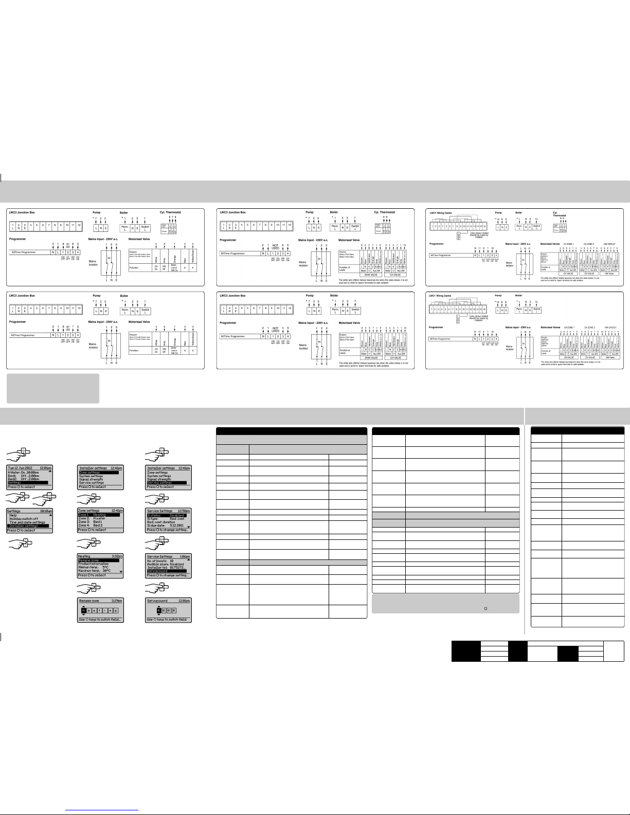
St ep 7: Connection Charts
Step 8: Installer Settings
Feature: Description: Factory Pre-Set:
Min on/off (*on ly
when Contr ol type
is On/o ff)
Select 1 mi n., 3 min., 5 min. or 10 min. 1 min.
Hysteresis (*only
when Contr ol type
is On/o ff)
Enable or disable Hysteresis Disabled
Frost Protection
*Heating zones
only
Enable or dis able the Fros t protecti on in the
MiTime uni t.
Disabled
Valve protection The output w ill be acti vated for the s pecifi ed time
(in minutes). T his will happe n weekly, relat ed to the
last act uation of the o utput. Sel ect 0 to 10 minut es.
0 minutes (Of f)
Screen lock Ena ble or disable t he lock in the M iTime unit .
To Lock: Enter a 3 dig it code for pro tection
To Unlock: Enter t he 3 digit code
000
Master Co de 401
Powersave To reduce power us e when not bei ng adjuste d.
Available options are: Powersave off, partial display
with key data , no display un til butt on press
Powersave off
System Res et
W
ill reset all settings to factory pre-sets
Signal Strength Informs ab out the curr ent signal st rength in th e various zone s
Service Settings To help compl y with regula tion 36 of the Gas s afety [Ins tallatio n & Use]
regulations 1998
Si Status Enable or disable Service mode Disabled
Si Typ e Select be tween, Red uced Comfor t, Switch ed Off &
No Effec t (warnings on ly)
Reduced Comfort
Reduced comfort
duration
Set the dura tion for the re duced comfor t setti ng
(0 to 60mins.)
15 min.
Si due date Set the date t he next boile r service i s due Toda y
Warning st art Set the number of d ays for the on- screen ser vice
due warning (0 t o 60 days)
30 days
Boost status Enable or disable Service Boost Disabled
No. of boost s Set the number o f Boosts to b e available af ter
service i s due (1 to 99)
10
Audible Alarm Enable or disable Service Alarm Enabled
Installer tel Enter the Installer telephone number if required
Set password Set password to re strict a ccess to the Se rvice
settings
0000
Feature: Description: Factory Pre-Set:
Installer Settings
! CAUTION! These settin gs should onl y be modifi ed by a qualifi ed person.
They can infl uence safe ty and the pro per func tioning of th e system.
Zone Settings Customise the MiTime according to personal requirements. These are
setting s which will b e applied to a co nnected r oom/cylin der stat .
Select zone S elect a zone f or the followi ng actions
Rename zone To rename an exi sting zone Heating, H Wat er,Bed 1
View Produc t
Information
View the prod uct detai ls, e.g. Part n umber,
Firmware revision etc.
Minimum temp It will not be possible to s et a lower temp erature 5C (Cyl stat = 40 C)
Maximum temp It will no t be possible t o set a higher te mperature 30C (Cyl stat = 70C)
Eco temp. Temperature used for energy saving periods e.g.
during the night
16C (Cyl stat = N/A)
Comfort temp. Temperature used for comfort periods e.g. during
the day
21C (Cyl stat = N/A)
Backlight settings Ava ilable optio ns are: On with t imeout, Al ways Off On with timeout
Temp. offset Adjust the di splayed temp erature to p ersonal nee ds 0C (Cyl s tat = N/A)
Screen lock Enable or dis able the loc k in the room unit
To Lock: Enter a 3 dig it code for pro tection
To Unlock: Enter t he 3 digit code
000
Master Co de 401
RF Binding Bind the remo te thermos tat to the rec eiver. Pre-bound
Delete zone
(not T710 R)
To delete an exis ting zone. The l ast zone can not
be deleted
Min. 1 Zone
Add Zone
(not T710 R)
Add a new zone, ap ply a name & bind a th ermosta t.
A time table c an be applied .
T720: Max. 2 Zon es
T740: Max. 4 Zone s
System Settings Thes e are the set tings which w ill be applied t o the MiTime u nit
View product
information
View the prod uct detai ls, e.g. Part n umber,
Firmware revision etc.
Backlight settings Available option s are: On with tim eout, Alway s On,
Always Off
On with time out
Control t ype
*Heating zones
only
Select TP I, TP or On/Of f. TPI = Use if the h ouse
usually rea ches setpoi nt in < 1 hour. TP = Use if t he
house usual ly reaches se tpoint in > 1 hou r
On/Off = Us e if the boile r should not sw itch
regularly, e.g . Solid fuel.
TPI
Cycle rate (*onl y
when Contr ol type
is TPI or TP)
Select 3 cp h (cycles per ho ur), 6 cph or 12 cph 6 cph
! IMPORTANT:
Always switch off the mains before removing
the MiTim e programmer – a nd never fi t it to a live
wall-plate!
Arrowed numbers relate to the junction box.
* Consult bo iler handbook f or details of p ump
overrun wiring.
Make the wirin g connection s, as above, for the
appropria te system. For su rface wiri ng, snap out the
cable entr y strip on th e bottom edge of t he wall-plate .
MiTime uni ts are double- insulated and ne ed no earth
connect ion, but an eart hing continui ty (loop) termina l is
provided for convenience.
After wir ing, plug in the uni t and tighten the s ecuring
screws. Che ck the mains inpu t has a 3A fuse, and swi tch
on the mains.
Bifl o sys tem: Model T720R
Bifl o sys tem: Model T720M
Twinzone system: Model T720R
3 Zone system: Model T740MTwinzone system: Model T720M
From the Home sc reen, selec t
Settings, then Installer settings
as shown.
If using the Se rvice featu re,
remember to se t the Password
when complete.
From here you ca n edit the
assigned zo nes, rename them i f
required and a djust the Ser vice
settings.
3 Zone system: Model T740R
Client
Schneider Electric
File Name
6490194_K Artwork.pdf
Artworker -
Proof Stage
PRINT
Finished Size 420x297mm
Creative Director Artwork % 100%
Modification Date
18/02/17 Bleed 3mm
Software version
Maximum Radiated
Power
Hereby, Schneider Electric Controls UK LTD, declares that this MiTime RF Packs is in
compliance with the essential
requirements and other relevant provisions of RED-DIRECTIVE 2014/53/EU. Declaration of conformity can be
downloaded on: www.draytoncontrols.co.uk
 Loading...