

Page 1
Client Invensys File Name 7406 Drayton Update M iStat N 064901910 01 IssF
Artworker -
Proof Stage
PRINT
Finished Size A3 297x420mm
Creative Director M ike Lane Artwork % 100%
Modification Date 18/05/15 9:36AM Bleed 3mm
What is a room thermostat?
... an explanation for householders
A room thermo stat simply s witches the he ating
system on an d off as neces sary. It works by s ensing
the air temper ature, switch ing on the heatin g when
the air temper ature falls bel ow the thermos tat sett ing,
and switchi ng it off once th is set temperat ure has
been reached.
Turning a room ther mostat to a high er setting w ill not
make the room hea t up any faster. How qui ckly the
room heats up d epends on the des ign of the heatin g
system, fo r example, the size of b oiler and radia tors.
Neither doe s the settin g affect ho w quickly the room
cools down. Turni ng a room thermos tat to a lower
setting w ill result in the ro om being contro lled at a
lower temperature, and saves energy.
The heating s ystem will not w ork if a time swit ch or
programmer h as switched i t off.
The way to set and u se your room ther mostat is to
fi nd the lowes t temperatu re setting tha t you are
comfort able with, and th en leave it alone to d o its job.
The best way t o do this is to set the ro om thermost at
to a low tempera ture – say 18ºC – and th en turn it up
by one degree ea ch day until you are co mfortable
with the temp erature. You won’t hav e to adjust the
thermost at furthe r. Any adjustment a bove this sett ing
will waste en ergy and cost yo u more money.
If your heatin g system is a boil er with radiato rs, there
will usually b e only one room ther mostat to con trol the
whole house. But you can have different temperatures
in individual rooms by installing thermostatic radiator
valves (TRVs) on i ndividual radi ators. If you don ’t
have TRVs, you sho uld choose a temp erature that is
reasonable f or the whole hous e. If you do have TRVs,
you can choos e a slightly highe r setting to ma ke
sure that even the coldest room is comfortable, then
prevent any over heating in othe r rooms by adjust ing
the TRVs.
Room thermo stats need a f ree fl ow of air to sen se
the tempera ture, so they mus t not be covered by
curtain s or blocked by fur niture. Nearby e lectric
fi res, telev isions, wall or t able lamps may preve nt the
thermostat from working properly.
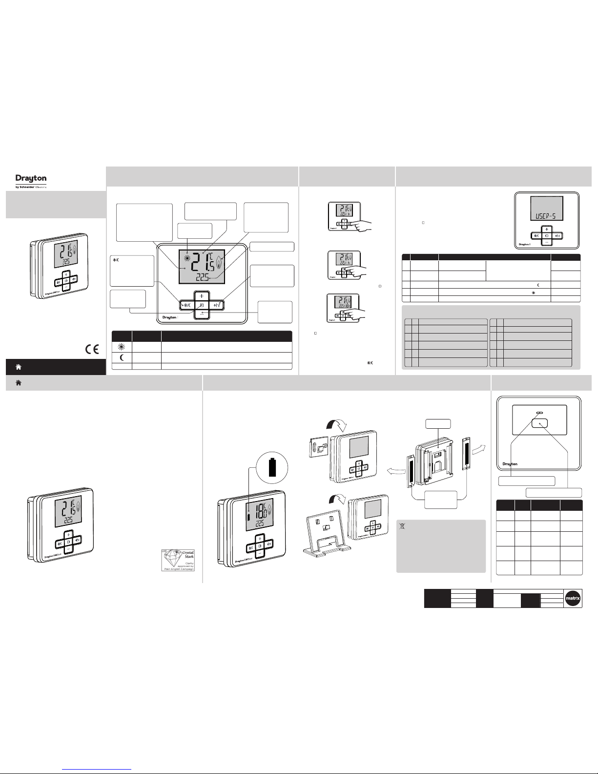
MiStatTM N
Room Thermostat
Model: N110R
Custome r Service Tel: 084 5 130 5522
Custome r Service Fax : 0845 130 0622
Technical Helpline: 0845 130 7722
Website: www.draytoncontr ols.co.uk
Email: customer.care@draytoncontrols.co.uk
l
@DraytonControls
x
/DraytonControls
EU Design Regs:- 0 02180638-1/2/3
User Guide 0649 0191001 Iss F
HOMEOWNER Guide
HOMEOWNER Guide
Symbol in
display
Function Description
Comfort setting
Select s the comfort s etting. The p re-set value i s used each time wh en activate d,
adjustab le within the use r settings (se e step 3).
Eco setting
Select s the Eco setti ng. The pre-se t value is used eac h time when act ivated,
adjustab le in the user set tings (see ste p 3).
None
Home screen
Indicates t hat the pre-se t temperatur es were changed vi a +/- key
St ep 1: Keys and Display - MiStat
RF Pack: MiStat N110R
Step 2: +hr (Timer)
MiStat
Press +hr to st art the Time r. The prior used
temperatu re and time will be di splayed and the
temperature will fl ash.
MiStat
Press +/- to adj ust +hr tempera ture, then press ( )
t o c o n fi r m .
Press +/- to adj ust +hr period be tween 0 and 23 hour s.
Press (
) t o c o n fi r m .
Step 3: Additional User Settings
ID Feature: Description: Factory Pre-Set:
1 MAX-TEMP
It will not be po ssible to se t a
higher temperature
If MAX-TEMP an d MIN-TEMP are s et to the
same value, i t will not be pos sible to chang e
temperat ure with the +/- keys .
30°C
2 MIN-TEMP
It will not be po ssible to se t a
lower temperature
5°C
3 ECO-TEMP
ECO Temperatur e used for ener gy saving per iods e.g. durin g the night ( )
16°C
4 COMF-TEMP
Comfort Temp erature us ed for comfor t periods e.g . during the day ( )
21°C
DONE
Exit from t he settin gs menu to USER-S
To enter User Settings
Press + & – keys for ap prox. 5
Seconds to enter the settings
menu as shown b elow.
Press Selec t (
) to enter the use r
settings.
Battery Handling
Batterie s, recharg eable or not , should not be d isposed
of into ordin ary house hold waste . Instead, t hey must be
recycled properly to protect the environment and cut down
the waste of precious resources.
Your local was te managem ent authori ty can sup ply detail s
concerning the proper disposal of batteries.
In complian ce with the EU D irective 2 006/66/EC, th e button
cell batte ry locate d on the print ed circuit bo ard inside t he
product , can be remove d at the end of th e product l ife, by
professional personnel only.
Step 4: Changing the Batteries
How do I know when to change
the batteries?
When the bat teries sta rt to run low a bat tery icon wi ll
fl ash in the dis play to indicate “ low batter y”, during
this time the M iStat will func tion normall y. When
the batte ry icon alone is s hown in the displa y, the
batteri es are completel y exhausted an d the MiStat will
cease to func tion (see below). Re -activat e by replacing
the batteries.
How to replace the batterie s
Remove the bat tery cover s as shown. Replac e the batteri es with 2 x 1.5V IEC LR6 (A A) Alkaline bat teries ensur ing
correct orientation. Replace the battery covers pressing fully home.
Battery Covers:
Slide outwards
to remove
MiStat Rear
Step 5: Receiver - Key & LED
Lamp
colour
Mode Action Key
Function
Green Normal Call for heat
(boiler is fi ring)
None
Green
Flashing
Normal RF
communication
None
Off Normal No call for hea t
(boiler is not
fi r i n g )
None
Red RF loss
or not
bound
No call for hea t Switches
the boiler
On
Amber RF los s
or not
bound
Call for heat Switches the
boiler Off
LED: See table b elow for detail s
Key: See table b elow for detail s
MiStat
MiStat
To set a suitable te mperature for u p to 23 hours, e.g.
for short term absence.
Now the timer is r unning. The tim e will be counted
down each hour.
Once the time h as elapsed, cont rol returns to t he prior
temperature screen.
The Timer ca n be cancelled by p ressing
key or by
setting t he +hr period to 0.
To exit User Sett ings
Press + & – keys for ap prox. 5
seconds to exit.
If there is no key pr essed for
2 minutes, th e system will ex it
the menu, any cha nges will be
saved.
Troubleshooting:
1 Setting temperature values is restricted
a
Are Minimum/Maximum temperatures activated?
see Homeown er Guide Step 3.
2
NO SIGNAL is vi sible on the sc reen, no reac tion on
key presses any more
a
Is the receive r powered? (Red s ignal lamp sho uld
be visible)
3 LOCKED is displayed
a see Installation Guide Step 5 - LOCK
MiStat
Current set temperature
Call for heat indication.
This fl ame wil l be visible
when the heating
temperature is below
the set tempe rature.
+hr key: Press to s et a
suitable temperature
for up to 23 hours (se e
step 2) .
Select key: Press
to open and save
editor screens
+ & - keys:
Press to chang e
the current
temperature.
Current room temperature
Current Setting,
see table be low
key: Press to toggle
between Comfort
setting, Eco setting and
Home
(Room thermostat only).
See table bel ow.
Customize the controller according to personal requirements.
4 Is the batte ry symbol v isible?
a Replac e batterie s, see Homeo wner Guide Ste p 4.
5
STARTING is vis ible on the sc reen, no reac tion on key
presses anymore
a
Is the receive r powered? (Red s ignal lamp sho uld
be visible)
6
WAIT is visible o n the screen, n o reaction o n key
presses anymore
a
Is the receive r powered? (Red s ignal lamp sho uld
be visible)
RF transmission indication. The
RF symbol wil l be visible as
follows,
Short fl ashes = RF transmis sion
Continuous fl ashing = RF signal
issue
Page 2
Client Invensys File Name 7406 Drayton Update M iStat N 064901910 01 IssF
Artworker -
Proof Stage
PRINT
Finished Size A3 297x420mm
Creative Director M ike Lane Artwork % 100%
Modification Date 18/05/15 9:38AM Bleed 3mm
1.2m
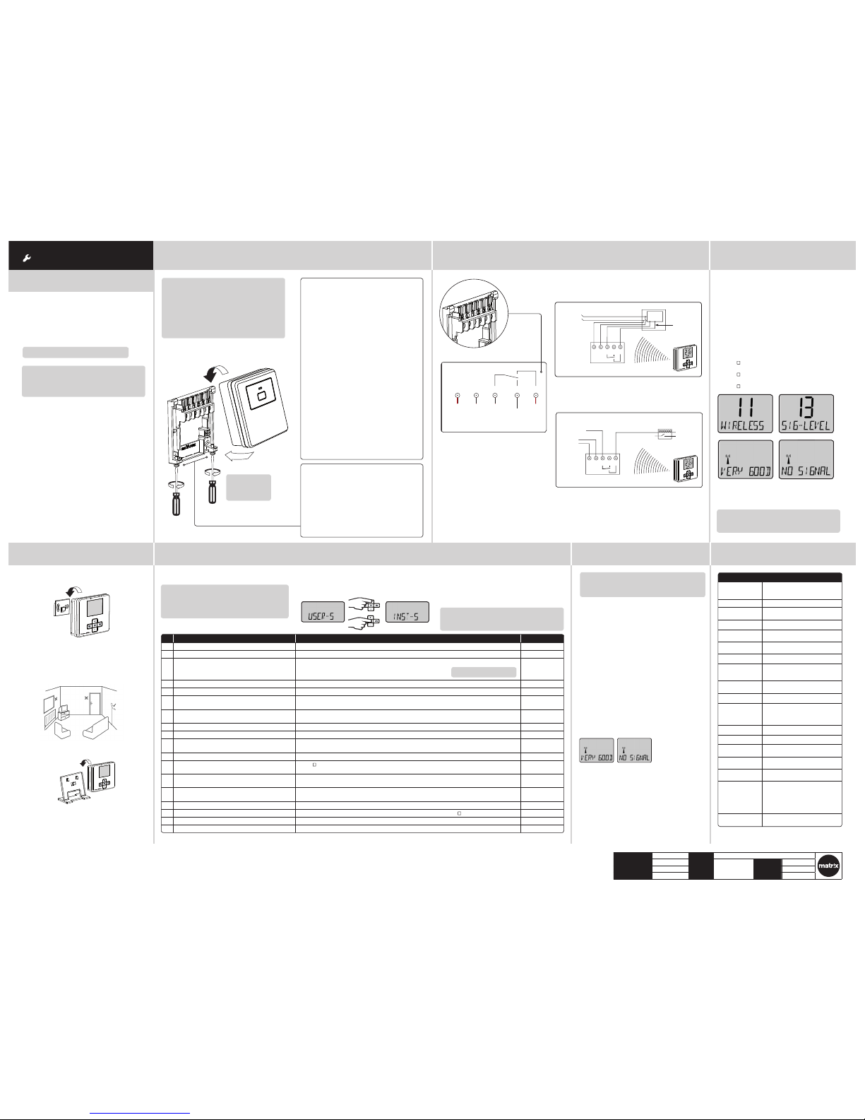
ID Feature: Description: Factory Pre-Set:
5 BACKLIGHT Available opt ions are: On with ti meout (TIMED), A lways Off (OFF ) TIMED
6 OFFSET Adjust displayed temper ature to suit per sonal needs (-5 to 5° C) 0.0°C
7 LOCK Protect MiS tat against un authorised u se. If active, an y key press will show LOC KED for a few Secs .
To lock: Enter your 3 di git code for prote ction.
To unlock: Press +& - key for approx. 5 sec . Enter your 3 digit c ode
000
Master cod e 401
8 CTRL-TYPE Confi gure th e control param eters for the sp ecifi c applic ation
9 CTRL-ALG Select TPI , TP or On/Off TPI
CYCL-RATE (only shows w hen CTRL-ALG is TPI
or TP)
Select 6 (GAS) c ph (cycles per hou r), 12 (ELECtric) cph or 3 (OIL) cp h 6 cph
HYST (only show s when CTRL-ALG is On /Off) Sele ct OFF, 0.1 to 5°C (OFF = No temperat ure hysteresi s, even on very low t emp. changes, th e
relay will swi tch over accordin g to MIN-OnOF F time)
0.5°C
MIN-OnO FF (only shows when C TRL-ALG is On/O ff) Selec t 1 to 30 minutes ( The minimum dura tion for the relay t o be On or Off) 5 min
DONE To exit CTRL-TYPE sub m enu
10 VALV- PROT The output will be ac tivated for t he specifi ed time (in Minutes). Thi s will happen week ly, related to
the last ac tuation of the o utput. Selec t OFF, 1 to 10 Minutes.
OFF
11 WIRELESS To create a radio link w ith the receive r or to view the RF sig nal quality Pre-bound
12 BIND Press (
) key to star t connecting t o the receiver.
NB. “binding” m ust also be ac tivated on the re ceiver, see Step 6 Com missioning
BINDING An RF connec tion to the rece iver will be create d. If success ful, the SIGNAL l evel will be displ ayed.
If unsucces sful, FAILED will b e displayed.
13 SIG-LEVEL Indicate s the quality of t he RF transmis sion
VERY GOOD, GOOD, POOR, NO SIGNAL
DONE To exit WIRELESS s ub menu
15 PROD-INFO View the prod uct details , e.g. Part number, Fir mware revision e tc. Use (
) key to show the det ails
16 RESET Will reset all set tings to fact ory pre-se ts OFF
DONE Exit from the set tings menu to INS T-S
INS TALL ATI ON Guide
Step 3: Signal Strength
The MiStat Roo m thermost at is prebound to th e
MiStat recei ver in the fact ory so they jus t need
to be positio ned in the best p lace for wireles s
communica tion. To help with this t here is a built in
Signal strength indicator, available in the Installer
setting s menu on the MiSta t thermosta t, as shown.
It is recommen ded that the sign al strength i s Good
or Very Good to ensure ongoing communication is
maintained.
To enter signal strength menu (see step 5 for more detail))
• Press + & - for app rox. 5 secs, th en scroll (+/-) to show
INST- S,
• press (
) to enter the installer menu,
• Press +/- until 11 WIRELE SS is shown,
• press ( ) to enter,
• press +/- to show 13 SIG- LEVEL as show n,
• press ( ) to see the current signal s trength.
Step 4: Mounting Options Step 5: Installer Settings
Once the bes t position ha s been identi fi ed, the MiSt at N
should be fi xed to the wall using the w all bracket as
shown.
Customize the MiStat according to application needs.
NB. MiStat ca n also be positi oned using the ta ble
stand included.
Care should b e taken to mount the t hermosta t in a
position wh ich is not subjec t to direct su nlight or
draughts. Preferably it should be mounted on an inside
wall about 1.2m (4f t) above the fl oor in a position where
it can respo nd to room temper ature but away fr om the
direct infl uence of radiato rs or other appl iances giving
off heat.
St ep 1: Mounting the Wall-plate Step 2: Wiring
! IMPORTANT:
Install ation must onl y be carried ou t by a
qualifi ed electrician or heating engineer.
Make sure mai ns input has a 3 amp f use.
! CAUTION! Before installation, make sure the
mains suppl y is switched o ff!
Option 2: Using an existing wall-plate
Loosen the se curing screws o n the old receive r
and unplug it . Check that ther e’s 20mm
clearance to t he right of the wal l-plate and 25mm
above it. Che ck the wiring diag ram for your
product mo del to compare ter minals and, if
necessar y, change the wir ing of the wall-pl ate to
suit. Now plu g the MiStat R unit i nto the
wall-plat e and tighten the se curing screw s.
Check the 3A fu se, and switch on t he mains.
Option 1: Fitting a new wall-plate
The ideal loc ation is close to t he boiler or cent ral
heating sys tem. For the bes t performa nce install
in an open space, a t least 30cm di stance from a ny
metal objec ts includin g wall boxes and the b oiler
housing. It is r ecommended th at the MiStat R is
mounted on th e wall nearest th e fi nal locatio n of
the MiStat N ro om unit and not les s than 30cm
from the boil er side panel.
Loosen the se curing screws , remove the wallpl ate
and, if surf ace wiring is to be u sed, snap out
the cable ent ry strip on t he bottom edg e of the
wallplate wi th a pair of pliers . Fix the wallplat e,
terminals at t he top, either dire ct onto the fl at
wall using wall p lugs and no 6 x1” wood screw s
or on a plasti c fl ush mounting s ingle conduit b ox
using M3.5 x 14 screws . Check that the re’s 20mm
clearance to t he right of the wal l-plate and 25mm
above it. Com plete the wirin g to the MiStat R
wallplate in ac cordance with t he wiring diagr am
in step 2, to comp ly with curren t IEE regulation s.
Place the MiSt at R onto the wallpl ate and tighten
the securing screws.
Check the 3A fu se, and switch on t he mains.
Warning: Installing th e MiStat R too clos e to the
metal side pa nel or mains cabl es may interfe re
with the rad io signal.
Applications
The electronic room thermostat MiStat N can be used
for temperature control together with:
• Boilers
• Oil and gas warm wat er heating
• Actuators o f fl oor heating s ystems or radi ators
• Circulating pumps
• Heat pumps
A MiSat R receiv er is required for op eration.
Note: To ensure a properly working heating
system, th e menu items in the I nstaller se ttings
have to be set acc ording to the need s of the
heating sys tem, see step 5 .
Note: To ensure a properly working heating system,
the menu item s in Installer s ettings have t o be set
according to t he needs of the hea ting system.
There can be ga ps in the ID number ing.
! DO NOT
use a surf ace
mounting box
This product is double insulated and
does not requi re an earth conn ection.
The MiStat R sh ould be wired to the
boiler or central heating wiring using the
correct t ype of cable or fl ex. The MiStat
R should be wire d to replace hard wi red
room or programmable thermostats,
as shown on the s ystem or boile r wiring
diagrams.
Always check other manufacturers
instructions for compatibility.
N L 1 2 3
230V AC 50Hz
Fused 3A
Common
heating
satisfied
or call for
cooling
Call for
heat
Volt free contacts
Combi boiler basic wiring layout
Zone control basic wiring layout
Note: If not bound, the bi nd screen will be vi sible.
For commissioning see Step 6
Note: Only needed if no t already bound, ie i f
replacing either the MiStat thermostat or the
MiStat receiver.
To exit Install er Setting s
Press +/- until ‘D ONE’ is shown, the n press ‘Selec t’ or
press + & – keys for a pprox. 5 seconds t o exit. If there
is no key presse d for 2 Minutes, th e system will ex it the
menu, any chang es will be saved.
1. Turn on power for the r eceiver. The red lamp w ill
come on. (if gree n lamp is visible, t he device is
already boun d, no further a ction neede d here)
(If a separate p rogrammer/T imer is fi tte d, ensure
that it is swi tched on)
2. P ush the butto n for >5 Seconds and th e LED will
fl ash red – yell ow – green --- - red – yellow - green…
3. Enter binding mode on the corresponding
MiStat room un it, see Step 5: Ins taller sett ings ,
it em 11
Important: It is essen tial, that the bin ding is
carried out between the corresponding room
unit and the re ceiver
4. I f binding is succe ssful, the si gnal strengt h will
be indicate d on both the MiSta t room unit and
the MiStat re ceiver as follows . If unsuccess ful,
FAILED will be dis played. If POOR SI GNAL
is displayed, l ook for a bette r location. If N O
SIGNAL is dis played, try con necting aga in with
the room unit in a d ifferent po sition.
MiStat Room U nit
MiStat Receiver
Immediately after binding, these signals will indicate
the signal quality for 1 minute.
• three green fl ashes = Very good si gnal
• double amber fl ashes = Good sign al
• single red fl ashes = Poor signal
• steady red = N o signal
To check the wireless connection
A green lamp on th e receiver will ind icate a good RF
connection.
To enter Installer Settings
Press + & – keys for ap prox. 5 Seconds to e nter the
setting s menu as shown.
Note: If not bound, the bi nd screen will be vi sible.
For commisioning see Step 6
Technical Data
Step 6: Commissioning
MiStat N110R & MiStat R111M
Supply voltage M iStat N: 2 x AA 1,5V a lkaline
batteries
MiStat R: 230V
Switch rating MiStat R: 2(1)A 230V a.c.
Ambient
temperature
Operatin g: 0°C to 45°C;
Storage: –20° C to 55°C;
Battery life Mi Stat N: 2 years (t ypically)
Temperature
range
5°C to 30°C
Temperature
resolution
0.5 °C, displ ay and sett ing
Control accuracy <0.6°C at 4°/ho ur
Wiring Mistat R: Fi xed wiring on ly, to comply
with curre nt IEE regulat ions (BS7671)
MiStat N: No wir ing require d
Mounting MiStat R: Ind ustry st andard wall plate
MiStat N: Wall br acket or tabl e stand
Radio frequency 868.3 (Bi-directional communication)
Radio signal range 30m typic ally. The rang e may be
affected by the composition / density
and number of wa lls betwee n the
MiStatN and MiStatR
Pollution degree 2
Software class A
Rated impulse
voltage
MiStat R: 2.5k V
Ball pressure test
temperature
MiStat R: 75°C
Energy Class IV = 2% (A ccording to EU 811/2013,
812/2 013, 813 /2013, 814/2 013)
Relevant EC
Directives:
2006/95/EC Lo w Voltage Dire ctive
2004/108/EC Electromagnetic
Compatibility Directive
1995/5/EC R&TTE Directive
2006/66/EC Battery Directive
2011/65/EU RoHS Direct ive
Applied
Standards:
EN60730-1; EN607 30-2-9
ETSI EN 300 220 -3; ETSI EN 301 4 89-3
eg. eg.
eg. eg.
User Code:
MiStat R
N L 1 2 3
L N -
Radio signals
to MiStat R - no wiring
Switched
230V AC
fused 3A,
Internal
boiler
electronics
External
controls
connections
N L 1 2 3
L
MiStat R
MiStat R
Switched live
from wiring
centre
Motorised valve
N
To boiler
and/or
pump
Radio signals
to MiStat R - no wiring
230V AC
fused 3A
N L 1 2 3
L -
N -
Radio signals
to MiStat R - no wiring
Switched
230V AC
fused 3A,
Internal
boiler
electronics
External
controls
connections
If POOR is displayed, look for a better location.
If NO SIGNAL is d isplayed, tr y connecting a gain with
the room unit in a d ifferent po sition.
Caution!
The radio rec eiver may be inst alled only by a co mpetent
electri cian in complian ce with the circu it diagram
enclosed in t he top housing cove r or in compliance
with these i nstruct ions. The curre nt safety reg ulations
must be obse rved.
In order to achi eve protectio n class II, adeq uate
installation measures must be taken.
This radio rec eiver, which can be in stalled sep arately,
is designed exc lusively for te mperature con trol in dry
and closed ro oms and standa rd environment s. This
electro nic device was crea ted according EN 60730-1, it
operates according working principle 1C.
It has to be plac ed in a location wh ere it will be able to
control the room temperature.
 Loading...