

Drayton MiStat C C110C Homeowner's Manual
What is a cylinder thermostat?
... an explanation for householders
A cylinder thermost at switches on and off the heat
supply from the boiler to the hot-water cyl inder. It
works by sensing the temperature of the wat er inside
the cylinder, switching on the water heatin g when the
temperature falls below the ther mostat setting, and
switching it off once this set temp erature has been
reached.
Turning a cylinder thermostat to a higher set ting will
not make the water heat up any faster. How quickly the
water heats up depends on the design of the heati ng
system, for example, the size of boiler and the heat
exchanger inside the cylinder.
The water heating will not work if a time switch or
programmer has switched it of f. And the cylinder
thermostat will not alway s switch the boiler off,
because the boiler sometim es needs to heat the
radiators.
Cylinder thermostat s are usually fitted between one
quarter and one third of the way up the cylinder. The
cylinder thermos tat will have a temperature scale
marked on it, and it should be set at between 60C and
65C, then left to do its job. This tempera ture is high
enough to kill off harmful bac teria in the water, but
raising the temperature of the st ored hot water any
higher will result in wasted energy and incre ase the
risk of scalding.
If you have a boiler control thermosta t, it should
always be set to a higher temperature than that of the
cylinder thermos tat. In most boilers, a single boiler
thermostat cont rols the temperature of water sent
to both the cylinder and radiators , although in some
there are two separate boiler ther mostats.
Drayton
MiStatTM C
Cylinder Thermostat
Model: C110C
Invensys
Customer Service Tel: 0845 130 5522
Customer Service Fax: 0845 130 0622
Technical Helpline: 0845 130 7722
Website: www.draytoncontrols.co.uk
E-mail: customer.care@invensys.com
l
@DraytonControls
x
/DraytonControls
EU Design Regs:- 002180638-1/2/3
User Guide 06490192001 Iss E
MiTime
MiStat
MiTime
MiStat
HOMEOWNER Guide
HOMEOWNER Guide
Step 5: Receiver - Key & LED
→
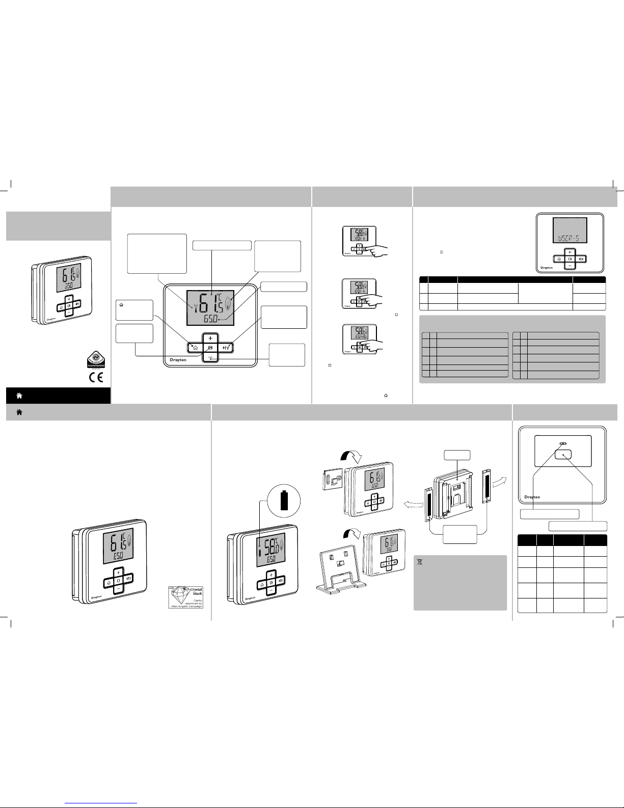
Step 1: Keys and Display - MiStat
RF Pack: MiStat C110C
→
Step 2: +hr (Timer)
Press +hr to start the Timer. The prior used
temperature and time will be displayed and the
temperature will flash.
Press +/- to adjust +hr temperature, then press ( )
to confirm.
Press +/- to adjust +hr period between 0 and 23 hours.
Press (
) to confirm.
→
Step 3: Additional User Settings
ID Feature: Description: Factory Pre-Se t:
1 MAX-TEMP
It will not be possible to set a higher
temperature
If MAX-TEMP and MIN-TEMP are
set to the same value, it will not be
possible to change tempe rature
with the +/- keys.
70°C
2 MIN-TEMP
It will not be possible to set a lower
temperature
40°C
DONE
Exit from the sett ings menu to USER-S
Lamp
colour
Mode Action Key
Function
Green Normal Call for heat
(boiler is firing)
None
Green
Flashing
Normal RF
communication
None
Off Normal No call for heat
(boiler is not
firing)
None
Red RF loss
or not
bound
No call for heat Switches
the boiler
On for 1hr
Amber RF loss
or not
bound
Call for heat Switche s the
boiler Off
→
Battery Handling
Batteries, rec hargeable or not, shoul d not be disposed
of into ordinary hou sehold waste. Inst ead, they must be
recycled proper ly to protect the enviro nment and cut down
the waste of preciou s resources.
Your local waste managem ent authority can su pply details
concerning the prope r disposal of batteri es.
In compliance with the EU Dir ective 2006/66/EC, the but ton
cell battery loc ated on the printed circui t board inside the
product, can be rem oved at the end of the product lif e, by
professional pe rsonnel only.
Step 4: Changing the Batteries
How do I know when to change
the batteries?
When the batteries st art to run low a battery icon will
flash in the display to indicate “low batter y”, during
this time the MiStat will functio n normally. When
the battery icon alone is show n in the display, the
batteries are complet ely exhausted and the MiStat will
cease to function (see below). Re-ac tivate by replacing
the batteries.
How to replace the batteries
Remove the battery cover s as shown. Replace the batteries with 2 x 1.5V IEC LR6 (AA) Alkaline bat teries ensuring
correct orienta tion. Replace the battery cover s pressing fully home.
Battery Covers :
Slide outwards
to remove
MiStat Rear
LED: See table below for details
Key: See table below for details
MiStat
MiStat
MiStat
MiStat
MiStat
To set a suitable temperature for up to 23 hours, e.g.
for short term absence.
Now the timer is running. The time will be counted
down each hour.
Once the time has elapsed, control retur ns to the prior
temperature screen.
The Timer can be cancelled by pressin g
key or by
setting the +hr period to 0.
Customize the controller acco rding to personal requirements.
To enter User Settings
Press + & – keys for approx. 5
Seconds to enter the setting s
menu as shown below.
Press Select (
) to enter the user
settings.
To exit User Settings
Press + & – keys for approx. 5
seconds to exit.
If there is no key pressed for
2 minutes the system will exit
the menu, any changes will be
saved.
✎ Troubleshooting:
1 Setting tempera ture values is restric ted
a
Are Minimum/Maximu m temperatures act ivated?
see Homeowner Guide Step 3.
2
NO SIGNAL is visible on the screen , no reaction on
key presses anymore
a
Is the receiver powered? (Red signal la mp should
be visible)
3 LOCKED is displayed
a see Installation Gui de Step 5 - LOCK
4 Is the battery symb ol visible?
a Replace batterie s, see Homeowner Guide Step 4.
5
STARTING is visible on the screen , no reaction on key
presses anymore
a
Is the receiver powered? (Red signal la mp should
be visible)
6
WAIT is visible on the screen, no reac tion on key
presses anymore
a
Is the receiver powered? (Red signal la mp should
be visible)
MiStat
Current hot water temperature
Current set temperature
Call for heat indication.
This flame will be visible
when the hot water
temperature is below
the set temperature.
+hr key: Press to set a
suitable temperatur e
for up to 23 hours (see
step 2).
Select key: Press
to open and save
editor screens
+ & - keys:
Press to change
the current
temperature.
key: Press to
cancel +hr and
display home.
RF transmission indica tion. The
RF symbol will be visible as
follows,
Short flashes = RF transmis sion
Continuous flashing = RF signal
issue
6444 Invensys MiStat C 06490192001 IssE.indd 1 27/09/2013 09:22
ID Feature: Description: Factory Pre-Se t:
5 BACKLIGHT Available options are: On with timeout (TI MED), Always Off (OFF) TIMED
7 LOCK Protect MiStat agains t unauthorised use. If active, any key press will show LOCKED for a few Secs.
To lock: Enter your 3 digit code for protection.
To unlock: Press +&- key for approx. 5 sec. Enter your 3 digit code
000
Master code 401
10 VALV-PROT The out put will be activated for the specified tim e (in Minutes). This will happen weekly, related to
the last actuation of the ou tput. Select OFF, 1 to 10 Minutes.
OFF
11 WIRELESS To create a radio link with the receiver or to view the RF signal quality Pre-bound
12 BIND Press (
) key to start connectin g to the receiver.
NB. “binding” must also be activ ated on the receiver, see Step 6 Commissioning
BINDING An RF connection to the receiver will be crea ted. If successful, the SIGNAL level will be displ ayed.
If unsuccessful, FAILED will be displaye d.
13 SIG-LE VEL Indicate s the quality of the RF transmission
VERY GOOD, GOOD, POOR, NO SIGNAL
DONE To exit WIRELESS sub menu
15 PROD-INFO View the product details, e.g. Par t number, Firmware revision etc. Use (
) key to show the details
16 RESET Will reset all settings to fac tory pre-sets OFF
DONE Exit from the settings menu to INS T-S
INSTALLATION Guide
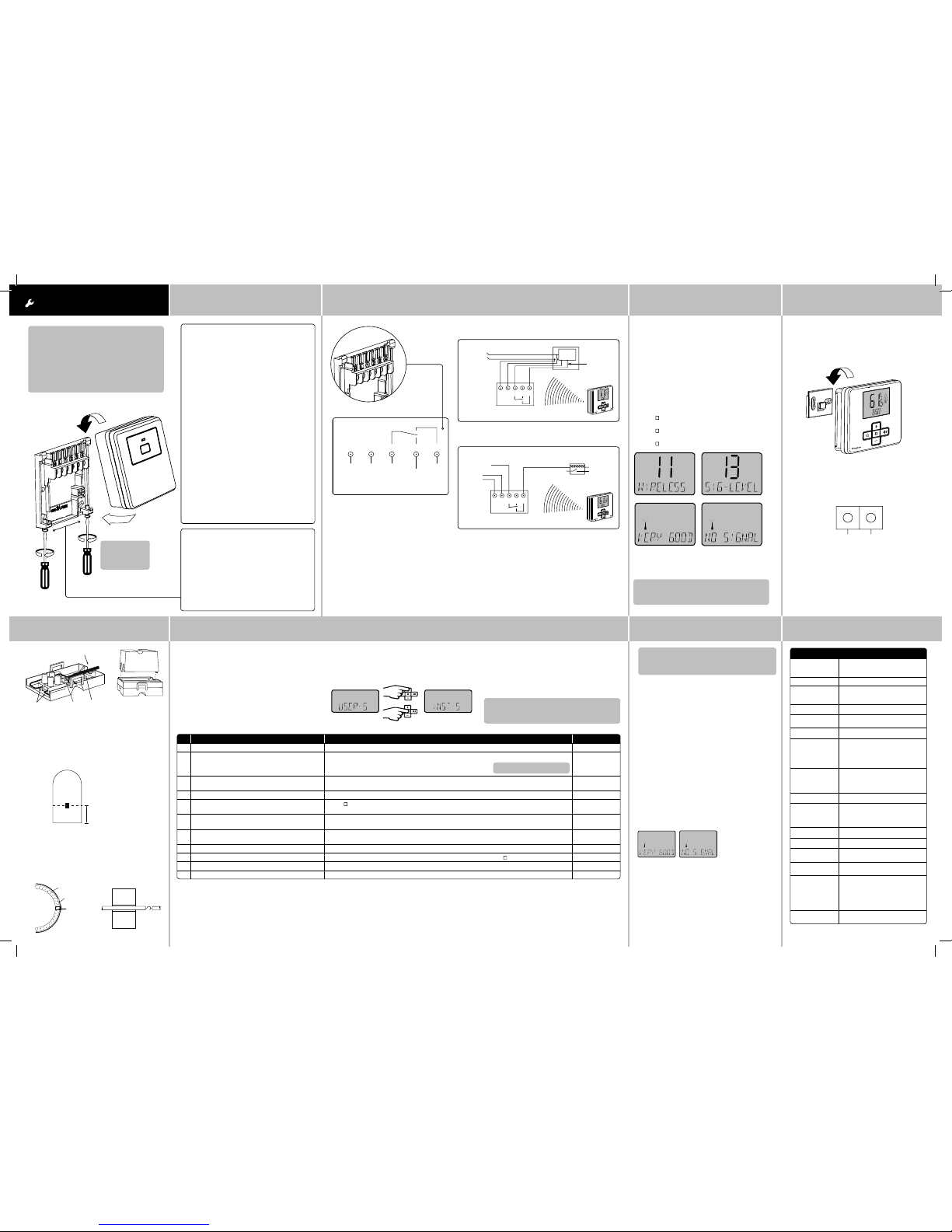
Step 3: Signal Strength
→
The MiStat Cylinder thermost at is prebound to the MiStat
receiver in the factor y so they just need to be positioned
in the best place for wireless communic ation. To help
with this there is a built in Signal strength indi cator,
available in the Installer set tings menu on the MiStat
thermostat, as show n.
It is recommended that the signal stre ngth is Good
or Very Good to ensure ongoing communicat ion is
maintained.
To enter signal strength menu (see step 5 for more detail)
• Press + & - for approx. 5 secs, then scroll (+/-) to show
INST-S,
• press (
) to enter the installer menu,
• Press +/- until 11 WIRELESS is shown,
• press ( ) to enter,
• press +/- to show 13 SIG-LEVEL as shown,
• press ( ) to see the current signal strength.
Step 4 (Continued) Step 5: Installer Settings
→
Customize the MiStat according to appl ication needs.
Step 1: Mounting the Wallplate
Step 2: Wiring
! IMPORTANT:
Installation mus t only be carried out by a
qualified electr ician or heating engineer.
Make sure mains input has a 3 amp fuse.
! CAUTION! Before inst allation, make sure the
mains supply is switche d off!
Option 2: Using an existing wall -plate
Loosen the securing screws on the old receiver
and unplug it. Check that there’s 20mm clearance
to the right of the wall-plate and 25mm above it.
Check the wiring diagram for your product model
to compare terminals and, if necessary, change
the wiring of the wall-plate to suit. Now plug the
MiStat R unit into the wall-plate and tighten the
securing screws.
Check the 3A fuse, and switch on the mains.
Option 1: Fitting a new wall-plate
The ideal location is close to the boiler or centr al
heating system. For the best pe rformance install
in an open space, at least 30cm distanc e from
any metal objects includ ing wall boxes and the
boiler housing. It is recommended that the
MiStat R is mounted on the wall nearest the final
location of the MiStat C room unit and not less
than 30cm from the boiler side panel.
Loosen the securing screws, rem ove the
wallplate and, if surface wirin g is to be used,
snap out the cable entry st rip on the bottom
edge of the wallplate with a pair of pliers. Fix the
wallplate, terminals at the top, either direc t onto
the flat wall using wall plugs and no 6 x1” wood
screws or on a plastic flush mounting single
conduit box using M3.5 x 14 screws. Check that
there’s 20mm clearance to the right of the wallplate and 25mm above it. Complete the wiring
to the MiStat R wallplate in accordance with the
wiring diagram in step 2, to comply with curren t
IEE regulations. Place the MiStat R onto the
wallplate and tighten the securing sc rews.
Check the 3A fuse, and switch on the mains.
Warning: Installing the MiSta t R too close to the
metal side panel or mains cables may inter fere
with the radio signal.
→ →
! DO NOT
use a surface
mounting box
This product is double insulated and
does not require an earth connec tion.
The MiStat R should be wired to the
boiler or central heating wiring usin g the
correct type of cab le or flex. The MiStat
R should be wired to replace hard wired
room or programmable thermos tats,
as shown on the system or boiler wiring
diagrams.
Always check other manufac turers
instructio ns for compatibility.
N L 1 2 3
230V AC 50Hz
Fused 3A
Common
heating
satisfied
or call for
cooling
Call for
heat
Volt free contacts
Combi boiler basic wiring layout
Zone control basic wiring layout
Note: If not bound, the bind screen will be visible.
For commissioning see Step 6
Note: Only needed if not already bound, ie if
replacing either the MiStat ther mostat or the
MiStat receiver.
To exit Installer Settings
Press +/- until ‘DONE’ is shown, then press ‘Selec t’ or
press + & – keys for approx. 5 seconds to exit. If there
is no key pressed for 2 Minutes, the system will exit th e
menu, any changes will be saved.
1. Turn on power for the receiver. The red lamp will
come on. (if green lamp is visible, the device is
already bound, no further ac tion needed here)
(If a separate programmer/Ti mer is fitted, ensure
that it is switched on)
2. Push the butto n for >5 Seconds and the LED will
flash red – yellow – green --- -red – yellow - green…
3. Enter binding mode on the corre sponding
MiStat room unit, see Step 5: Installer set tings ,
item 11
Important: It is esse ntial, that the binding is
carried out betwe en the corresponding room
unit and the receiver
4. If binding is success ful, the signal strength will
be indicated on both the MiStat room unit and
the MiStat receiver as follows. If unsucc essful,
FAILED will be displayed. If POOR SIGNAL
is displayed, look for a better locat ion. If NO
SIGNAL is displayed, try conne cting again with
the room unit in a different positio n.
MiStat Room Unit
MiStat Receiver
Immediately after bindin g, these signals will indicate
the signal quality for 1 minute.
• three green flashes = Very good signal
• double amber flashes = Good signal
• single red flashes = Poor signal
• steady red = No signal
To check the wireless connectio n
A green lamp on the receiver will indicate a good RF
connection.
→
To enter Installer Setting s
Press + & – keys for approx. 5 Seconds to enter the
settings menu as shown.
Note: If not bound, the bind screen will be visible.
For commisioning see Step 6
Technical Data
Step 6: Commissioning
MiStat C110C & MiStat R111M
Supply voltage MiStat C: 2 x AA 1,5V alkaline
batteries
MiStat R: 230V
Switch rating MiStat R: 2(1)A 230V a.c.
Ambient
temperature
Operating: MiStat C 0°C to 50° C;
MiStat R 0º to 45ºC
Storage: –20°C to 55°C;
Battery life MiStat C: 2 years (typicall y)
Temperature
range
40°C to 70°C
Control accurac y +/- 8°C
Wiring MiStat R: Fixed wiring only, to compl y
with current IEE regula tions (BS7671)
MiStat C: No wiring required
MiStat Sensor: Ø0.5mm 2 2 core
cable between Sen sor & MiStat.
Mounting MiStat R: Industr y standard wallplate
MiStat C: Wall bracket
MiStat Sensor: Direc t mounting onto
cylinder
Radio frequency 868.3 (Bi-direction al communication)
Radio signal range 30m t ypically. The range may be
affected by the com position / density
and number of walls betwee n the
MiStat C and MiStat R
Pollution degree 2
Software cla ss A
Rated impulse
voltage
MiStat R: 2.5kV
Ball pressure tes t
temperature
MiStat R: 75°C
Relevant EC
Directives:
2006/95/EC Low Voltage Direc tive
2004/108/EC Electro magnetic
Compatibilit y Directive
1995/5/EC R&TTE Directive
2006/66/EC Batter y Directive
2011/65/EU RoHS Directive
Applied
Standards:
EN60730-1; EN60730-2-9
ETSI EN 300 220-3; ETSI EN 301 489-3
eg. eg.
eg. eg.
User Code:
MiStat R
N L 1 2 3
L N -
Radio signals
to MiStat R - no wiring
Sw
i
tched
230V AC
fused 3A,
Internal
boiler
electronics
External
controls
connections
N L 1 2 3
L
MiStat R
MiStat R
Switched live
from wiring
centre
Motorised valve
N
To boiler
and/or
pump
Radio signals
to MiStat R - no wiring
230V AC
fused 3A
N L 1 2 3
L -
N -
Radio signals
to MiStat R - no wiring
Sw
i
tched
230V AC
fused 3A,
Internal
boiler
electronics
External
controls
connections
If POOR is displayed, look for a better loca tion.
If NO SIGNAL is displayed, try connec ting again with
the room unit in a different positio n.
→
Step 4: Mounting Options
The MiStat C should be located in a convenient position
for the end user, close to the domestic hot water cylinder
being controlled.
Once the best position has been identified, the MiStat
C should be fixed to the wall using the wall bracket as
shown.
MiStat
Wiring
Cylinder Thermostat
External Sensor
Cylinder Thermostat Sensor
Locate the external sens or terminal block on the lower
edge of the MiStat C thermostat , connect a 2-core
cable, cut to the required length to reach the sens or
position. Connec t to the sensor in the position shown
and fold wires back through the cable grip & out
through the cable entry, re-as semble the housing.
Clip the spacer
provided onto
the sensor
housing
The sensor should be installe d approximately one
third of the way up the hot water cylinder. With preinsulated cylinders , mark the position and size, and
remove just enough insulation to allow the sens or to fit
against the metal of the cylind er in the recess formed.
The plastic covered spring fixing cable should be cut
to an un-stretched length of approximately 60-75mm
(2½”-3”) less than the circumference of the cylinder
and the hook and eyelet should be screwed into the
ends. Stretch the cable round the cylinder, over the
insulation, and position it in the groove across the front
of the sensor housing, Engage the hook and eyelet.
1/3 cylinder height
Cylinder
Insulation
Fixing cable
Sensor
Sensor
Cylinder
→
Cable entry
Connect here NTC
Sensor
Cable
grip
6444 Invensys MiStat C 06490192001 IssE.indd 2 27/09/2013 09:23
 Loading...