

Drayton miGenie Wish 1 T714R, miGenie Wish 2 T724R, miGenie Wish 3 T744R Installation Manual
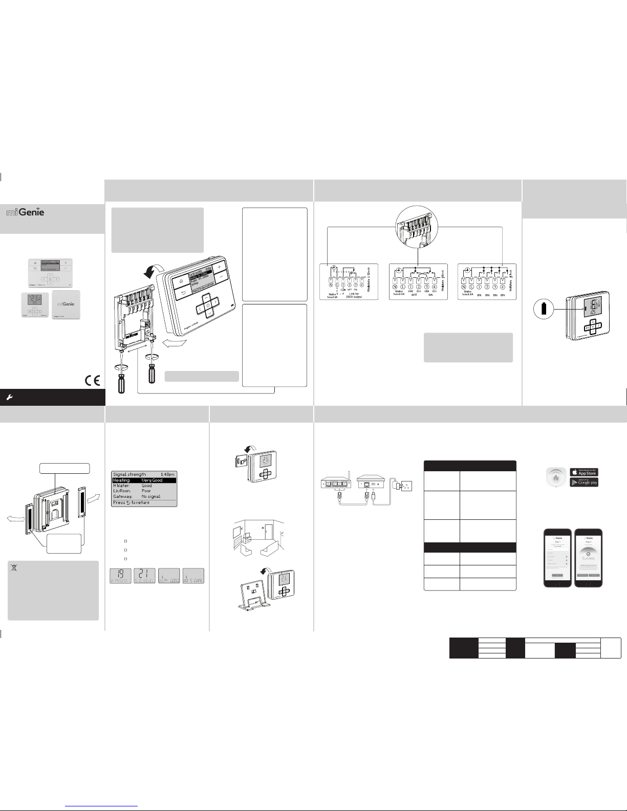
St ep 1: Mounting the Wall-plate
! IMPORTANT:
Install ation must on ly be carried ou t by a
qualified electrician or heating engineer.
Make sure mai ns input has a 3 amp f use.
! CAUTION! Before installation, make sure the
mains supp ly is switche d off!
Option 1: Fitting a new wall-plate
The ideal loc ation is 1.2m above
floor level, with reasonable
lighting, go od access, no
condensation, no extremes of
temperature and a supporting
surface t hat fully cover s the
back of the uni t. Position wit h
70mm clearance to the right,
25mm above and sufficient room
to access th e securing scre ws
underneath. Fix, with terminals
at the top, eith er direct to a flat
wall using wal l plugs and No. 6 x
1” (25mm) woodscrews , or on a
flush mounting single conduit box
type UA1 (BS4662) usin g M3.5 x
14 bolts. Chec k the 3A fuse, and
switch on th e mains.
! DO NOT use a sur face mountin g box
→
Option 2: Usi ng an existing
industry standard wall-plate
Loosen the securing screws
on the old prog rammer and
unplug it. Ch eck that there is
70mm clearance to the right of
the wall-pl ate and 25mm above
it. Check th e wiring diagram f or
your product model to compare
terminals and, if necessary,
change the wi ring of the wallplate to suit . Now fit the miGeni e
controller i nto the wall-pl ate and
tighten the securing screws.
Check the 3A fu se, and switch on
the mains.
Wireless Packs
Technical Helpline: 0333 7000 622
Website: www.draytoncontrols.co.uk
www.mi-genie.co.uk
E-mail: customer.care@draytoncontrols.co.uk
l
@DraytonControls
x
/DraytonControls
EU Design Regs:- 002180638-1/2/3
Installer Guide 06490211001 IssE
INS TALL ATI ON Guide
Single Channel : miGenie Wish 1 T714R
Dual Channel: miGenie Wish 2 T724R
Multi Channel: miGenie Wish 3 T744R
Step 2: Wiring
→
Step 3: continued...
Step 4: Signal Strength
Step 5: Mounting Options
Step 6: Install the miGenie Gateway & miGenie app
→ →
→
→
The miGenie t hermostat (s) & miGenie gateway a re
pre-boun d to the miGenie con troller in the fa ctory so
they just ne ed to be position ed in the best pl ace for
wireless co mmunication . To help with this there i s a
built in signa l strength ind icator, available i n the Zone
Setting s menu on the miGen ie controller, as sho wn.
It is recomme nded that the sig nal strength i s Good or
Very Good to ensure communication is maintained.
The signal s trength can al so be seen on the mi Genie
thermostat.
To enter the Signal Strength menu
• Press + & - fo r approx. 5 sec s, then scroll (+/-) to show
10. A DV-S ET,
• Press (
) to enter the Advanced Settings menu,
• Press +/- until 19 WIREL ESS is shown,
• Press ( ) to enter the Wireless menu,
• Press +/- to show 21 SIG -LEVEL as sh own,
• Press ( ) to see t he current sign al strength .
miGenie ther mostat rear
Battery Covers:
Slide outwards
to remove
Once the bes t position has b een identified , the
miGenie ther mostat sho uld be fixed to the wal l using
the wall brac ket as shown.
Location & Wiring
The miGenie ga teway is designe d to be placed
on a flat surf ace and should be l ocated next t o the
customer’s internet router. A short ethernet cable is
provided to co nnect the miG enie gateway to a spa re
LAN por t on the back of the in ternet route r (see
image b elow).
Creating a User Account
Note: You can only cr eate a User Accoun t when your
miGenie Wire less Pack has bee n fully insta lled.
You will first nee d to download the Dr ayton miGeni e
app for your sma rtphone or t ablet which is ava ilable
from the App St ore or Google Play.
The app guide s you through the reg istration p rocess
which conne cts your miGe nie system to you r e-mail
address. D uring this proce ss you will be asked t o
press the bu tton on the bac k of the miGenie gat eway
which will flas h green until the c onnection is m ade.
A verificat ion e-mail will b e sent to you to confir m
your e-mail a ddress before t he app can be used .
Once the gate way has been regis tered the sys tem
is ready to cont rol your heating a nd hot water.
To control your miGenie system from additional
smartph ones or tablet s simply downlo ad and install
the app and log in using the same e -mail address
and password.
NB. miGenie th ermostat c an also be posit ioned using
the table stand included.
The miGenie ga teway is powered f rom a standar d
mains wall soc ket using the supp lied adaptor pl ug.
Care should b e taken to mount th e miGenie therm ostat
in a posi tion which is n ot subject to d irect sunli ght or
draughts. Preferabl y it should be mou nted on an inside
wall about 1.2m (4f t) above the floor in a p osition where
it can respo nd to room temper ature but away f rom the
direct infl uence of radiat ors or other appl iances giving
off heat.
Status
The miGenie gateway reports status information
on the LED loc ated on the rear of th e product.
An overvie w of the status i nformation is g iven in the
table below:
Connect t he wiring as show n above.
T714R only: Note tha t the output con tacts are
voltage- free, so power ne eds to be put on to
Terminal 1 eithe r by linking from Termin al L or
from a separa te supply with a 3A f use.
! IMPORTANT:
Always switch off the mains before removing
the miGenie c ontroller an d never fit it to a live
wall-plate!
eg.
eg.
It has to be plac ed in a location w here it will be able t o
control the room temperature.
If POOR is displayed, look for a better location
If NO SIGNAL i s displayed, tr y connectin g again with
the room unit i n a different po sition. To exit, pre ss + &
- keys for approx . 5 seconds. If th ere is no key pressed
for 2 minutes , the menu will be exi ted automatic ally.
1.2m
Client
Schneider Electric
File Name
6490211_E Artwork.pdf
Artworker -
Proof Stage
PRINT
Finished Size 42 0x297mm
Creative Director
N/A
Artwork % 100%
Modification Date
18/02/17
Bleed 3mm
123
LAN
WAN
LED State
(During Setup)
Activity
Cycling through Red,
Amber, Green
The miGenie gateway is attempting
to bind to a miGe nie Controll er.
Can be star ted manual ly by
pressing and holding the gateway
button for 5 seconds.
Off Indicates that either;
- the miGenie g ateway is not
connected to the miGenie controller.
or
- the miGenie g ateway has not b een
register ed with an inte rnet accoun t
and app.
Green flashing every
1 second
This occur s when the but ton on the
rear of the gat eway is press ed. The
miGenie gateway is attempting to
connect t o a miGenie app vi a the
internet . This mode wil l time out
after 5 minutes.
LED State (During
normal use)
Activity
Green Indicate s 'all OK' – the gate way is
connected to the miGenie controller
and interne t control is av ailable.
Solid Red No RF signal – th e device shou ld
be relocat ed closer to th e miGenie
controller.
Solid Amber No interne t connecti on – check the
status of t he local int ernet route r
and all cabling.
Single Channel:
miGenie T714R
Dual Channel:
miGenie T724R
Multi Channel:
miGenie T744R
Ch1 Ch2 Ch3 Ch4
Step 3:
miGenie Thermostats
- Checking the batteries
How do I know when to change
the batteries?
When the bat teries sta rt to run low a bat tery icon
will flash in the d isplay, to indicat e “low batter y”
during this t ime the miGenie th ermostat w ill function
normally. Plea se replace bat teries with 2 x 1.5V
IEC LR6 (AA) Alk aline batte ries. When the ba ttery
icon alone is sh own in the display, th e batteries a re
completely exhausted and the miGenie thermostat
will cease to f unction (see be low).
Re-acti vate by replaci ng the batter ies.
Battery Handling
Batteri es, rechar geable or not , should not b e disposed
of into ordi nary house hold wast e. Instead, t hey must be
recycled properly to protect the environment and cut
down the was te of precio us resourc es.
Your local waste management authority can supply
details concerning the proper disposal of batteries.
In complian ce with the EU D irective 2 006/66/EC, th e
button ce ll batter y located on t he printed c ircuit boar d
inside the p roduct, c an be removed a t the end of the
product life, by professional personnel only.
How to replace the batterie s
Remove the bat tery cover s as shown. Replac e the
spent bat teries with 2 x 1.5V I EC LR6 (AA) Alkalin e
batteries ensuring correct orientation. Replace the
battery covers pressing fully home.
Drayton
401 Southway Drive
Plymouth
PL6 6QT
United Kingdom
Add and Remove De vices
(NB: only req uired if addi ng a new therm ostat. Al l items in the W ish 1, 2 & 3 packs are p re-bound )
To manually connec t a miGenie the rmostat, in sert the bat teries into t he thermost at and wait for “Bi nd?” to be
displayed, pr ess ( ) to select. You will als o need to enter the b inding proces s on the miGenie Con troller, by enterin g
the Advance d Settings me nu, then the Zone s ettings and s elect the Dev ice manager opti on. In this scree n select
the Add ther mostat opti on to complete the b inding proces s. To remove a miGenie The rmostat ent er the Device
manager opti on in the miGenie co ntroller usin g the same sequen ce detailed abo ve. The option will n ow display
Remove Therm ostat, sel ect this opti on and the thermo stat will be rem oved from the sy stem.
To manually connec t a miGenie gate way, press and hold t he button on th e rear of the gateway f or more than 5
seconds, th e LED will repeate dly flash red-ye llow-green. You wil l also need to enter t he binding proce ss on the
miGenie Controller, by entering the Advanced Settings menu, then System settings, then Internet options. In this
screen sele ct the Add gate way option to comp lete the binding p rocess. To remove a miG enie Gateway ente r the
Internet op tions menu in the m iGenie control ler using the sam e sequence det ailed above. The me nu will display
Remove gatewa y, select this opt ion and the gatew ay will be removed fr om the system.
Technical Data
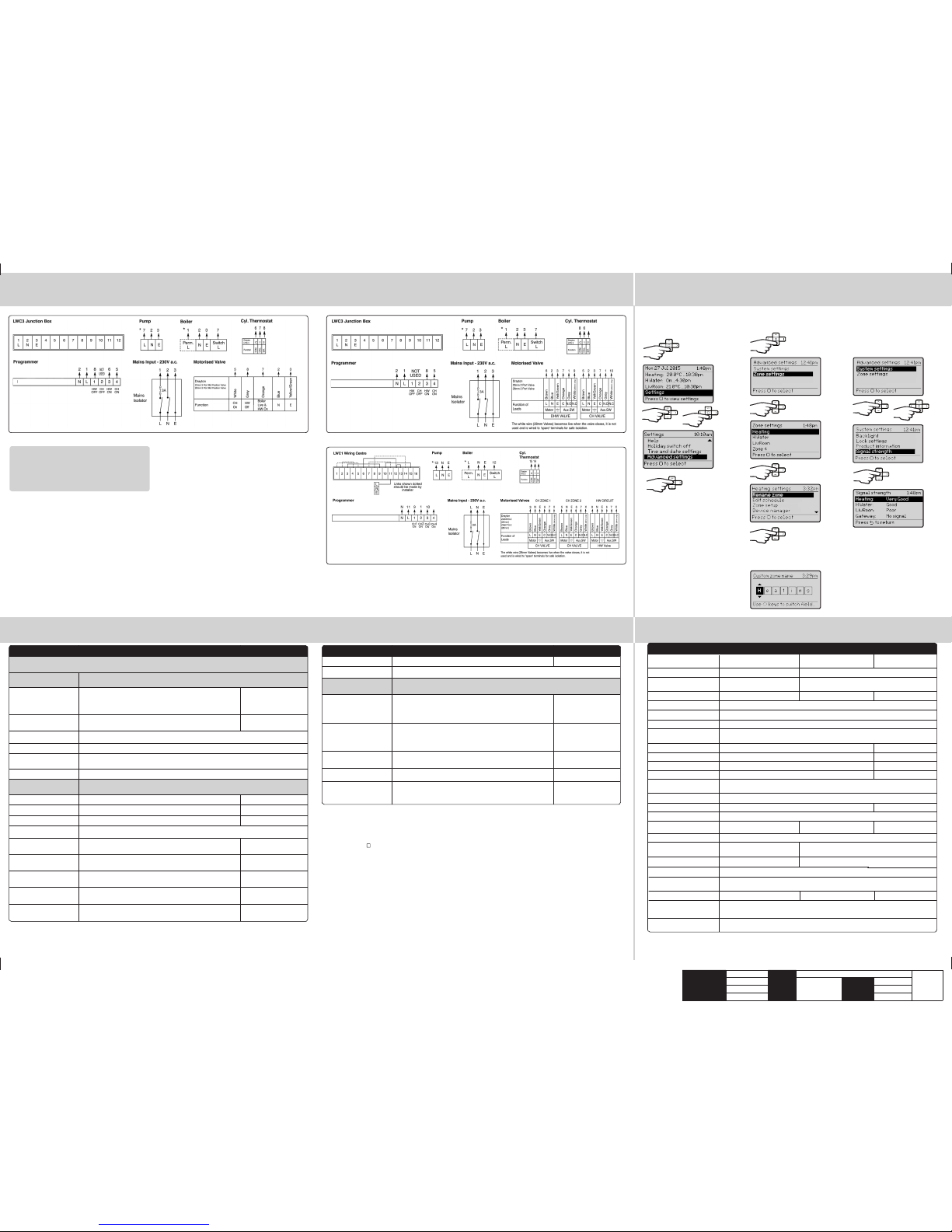
St ep 7: Connection Charts
Step 8: Advanced Settings
Step 8: Advanced Settings
→
→
Feature Description Factory Pre-Set
Device manager Add, replace or remo ve RF room ther mostat s Pre-bound
Signal strength Displays th e signal str ength of the se lected zon e, if a miGenie th ermosta t is connec ted to the zone
Channel settings (within
Zone settings)
Customis e the applica tion type a nd associa ted control s ettings f or zones follo wing this
application type
Application type Selecting the application type pre-configures
the available zone information
Zone 1: Heating:
Zone 2: Hot Water
Zone 3: Heatin g
Zone 4: Unused
Control t ype
*Heating zones only
Select TP I or TP.
TPI = Use if the h ouse usually r eaches set point in ≤ 1 hour.
TP = Use if the ho use usually re aches setp oint in ≥ 1 hour.
TPI
Cycle rate (only w hen
control t ype is TPI or TP)
Select 3 cp h (cycles per ho ur), 6 cph or 12 cph 6 cph
Frost temperature Disable frost p rotectio n or set betw een 3-10°C 5°C
Valve protection The output will b e activat ed for the spec ified time (in m inutes). This
will happen w eekly, relate d to the last ac tion of the ou tput. Sel ect 0
to 10 minutes.
0 mins (Off )
Feature Description Factory Pre-Set
Advanced settings
! CAUTION! These settin gs should onl y be modifie d by a qualified p erson. The y can influenc e the
safety an d the proper f unction ing of the sys tem
System settings These are se ttings app licable to t he system co ntroller uni t, global se ttings
for bound nodes and internet connection settings
Backlight miGenie controller options are:
On with time out, Alway s on, Always of f
miGenie thermostat options are:
On with time out, always o ff
On with time out
Lock settings Enable or disable the screen lock for the miGenie controller. To lock:
enter a 3 digit c ode for prote ction. To unloc k: enter the 3 di git code
000
Master cod e 401
Product Information View product detai ls for devices i n the syste m e.g. part num ber, firmware ver sion, etc.
Signal strength Informs abo ut the curre nt signal st rength of the p roducts c onnecte d to the syste m
Internet options Sub-menu rela ting to the con nection of a n internet g ateway – enable s
a gateway to be a dded, replac ed or removed wi th an indica tion of signal s trength.
System res et Will reset al l setting s to factor y pre-set s
Zone settings Customise each zone according to personal preferences
These are se tting whic h will be appli ed to a connec ted thermos tat
Select zone Select th e zone for the fol lowing act ions
Rename zone To rename an existing z one Heating, H Wat er, LivRoom
Edit schedule Update the sch edule for the zo ne
Zone setup Contains detaile d zone setup va lues – see belo w for descrip tions
Minimum
temperature
The minimum s et temperat ure that can b e set
for the zone
5°C
Maximum
temperature
The maximu m set tempera ture that ca n be set
for the zone
30°C
Eco
temperature
Temperature used for energy saving events
e.g. during the night
16°C
Comfort
temperature
Temperature used for comfort events
e.g. during th e day
21°C
Offset
temperature
Adjust the d isplayed tem perature to p ersonal ne eds 0°C
! IMPORTANT:
Always switch off the mains before removing
the miGenie C ontroller – a nd never fit it to a live
wall-plate!
→
Arrowed numbers relate to the junction box.
* Consult bo iler handboo k for details of p ump
overrun wiring.
Make the wirin g connection s, as above, for the
appropria te system. For su rface wiri ng, snap out the
cable entr y strip on th e bottom edge of t he wall-plate .
miGenie controllers are double-insulated and need
no earth co nnection, bu t an earthing c ontinuity (lo op)
terminal is provided for convenience.
After wir ing, clip on the uni t and tighten the s ecuring
screws. Che ck the mains inpu t has a 3A fuse, and swi tch
on the mains.
Biflo system: Model T 724R Twinzone system: Model T724R
From the Home sc reen, selec t
Settings, then Advanced settings
as shown.
From here you ca n edit the assign ed zones, rename t hem if required
and check the S ignal streng th.
→
→
→
→ →
→
→
→
→
Client
Schneider Electric
File Name
6490211_E Artwork.pdf
Artworker -
Proof Stage
PRINT
Finished Size 42 0x297mm
Creative Director
N/A
Artwork % 100%
Modification Date
18/02/17
Bleed 3mm
miGenie Controller
miGenie Controller
3 Zone system: Model T744R
miGenie Controller
Select a na me from the list o r
select 'Cu stom zone name' to
create a new zon e name.
miGenie controller miGenie thermostat miGenie gateway
Power Supply 230V a.c. +10% -10% 50Hz 2 X 1.5V IEC LR6(AA) al kaline
batteries
5V d.c. 1A USB Micr o-B
Switch Rating 2 (1) A 230V a.c. each swi tch N/A
Wiring Fixed wiring on ly, to comply wi th
current IE T regulatio ns (BS7671)
No wiring required
Battery life N/A 2 years typical N/A
Ambient Temperature
Operating: 0º to 45ºC (miGe nie controll er 3 / 4 channel 0 º to 40ºC)
Storage: -20ºC to 55ºC
Ambient humidity
(non condensing)
Operatin g 25% to 90%
Storage 15% to 95%
Temperature Range 5 ºC - 30 ºC N/A
Control Accuracy <0.6ºC at 4º / hour N/A
Timing resolution 1 minute N/A
Temperature resolution 0.5°C N /A
Ball Pressure Test
Temperature
75ºC
Pollution Degree 2
Energy Class IV = 2% (Acc. EU 811/2013, 812/2013, 813/2013, 814/2013) N/A
Software Class A
Software Version
Maximum Radiated Power
Without Mains Power
Display: bl ank; Time: alw ays kept
Program tim es: always pre served
N/A
Rated Impulse Voltage
2.5kV
Radio Frequency
N/A
868.3MHz (Bi-directional communication)
Radio Signal Range 30m typic ally. The rang e may be affe cted by the co mposition / d ensity an d the number
of walls bet ween the miGe nie produc ts
Mounting Industry standard wall plate Wall bracket or tab le stand Table top
Relevant EC Directives:
2014/53
/EU RED Directive
2013/56/EU Battery Directive
2011/65/EU RoHS Directive
App
lied St
andards:
EN60730-1; EN607 30-2-7; EN60730 -2-9
EN 300 22
0-2; EN 301 489-3
Hereby, Schneider Electric Controls UK LTD, d
eclares that this miGenie Wireless Packs is in compliance with the
essential requirements and other relevant provisions of RED-DIRECTIVE 2014/53/EU. Declaration of conformity
can be downloaded on: www.draytoncontrols.co.uk
6712076
6712077
6712075
+11dBm (12.6mW)
 Loading...